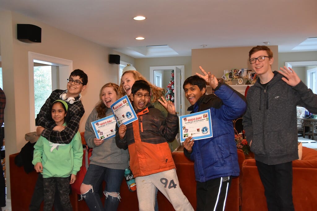
We have been doing Amateur Radio open house activities as part of our High-Altitude Balloon projects and Kids Day for some time now. These events help young people to learn about and have fun with Amateur Radio and help us to create a STEM learning experience based upon Amateur Radio.
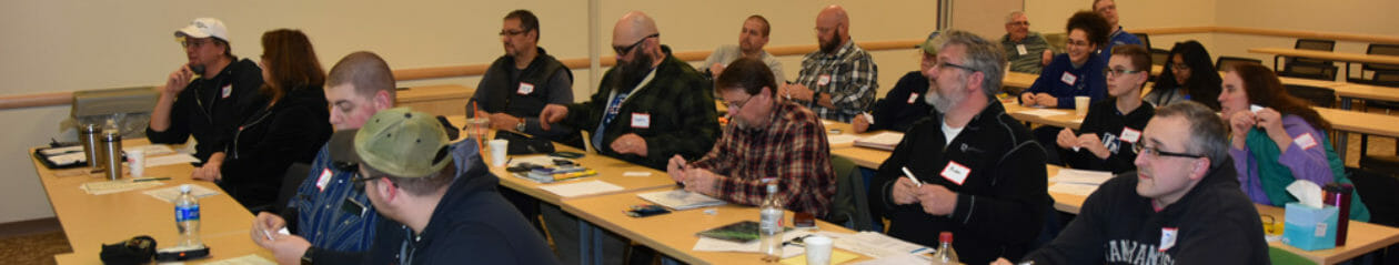
Earlier this year, we began working on a project to scale our open house activities up to become an activity that we could host at local Ham Fests. We wanted to expand the scope of this activity to appeal to young people and all Hams to provide an opportunity to learn about Amateur Radio and to showcase some of the modern, “high-tech” aspects of the Amateur Radio Service. This project was debuted at the NETT event at NEAR-Fest.
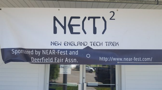
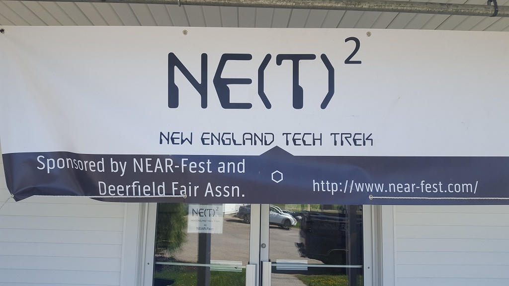
Concurrently, Bill Barber, NE1B who is a Nashua Area Radio Society (NARS) member began working on a youth outreach event for the NEAR-Fest event held in Deerfield, NH. We got together with Bill, the NEAR-Fest leadership, and others to create the New England Tech Trek (NETT) at NEAR-Fest. We held our first NETT event earlier this month.
NARS contributed 10 displays to the initial NETT event including:
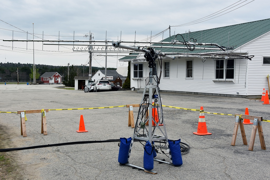
- A Satellite Communication Display and a Computer Controlled Satellite Get On The Air Station
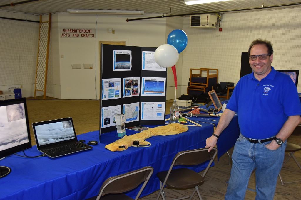
- A High Altitude Balloon Display
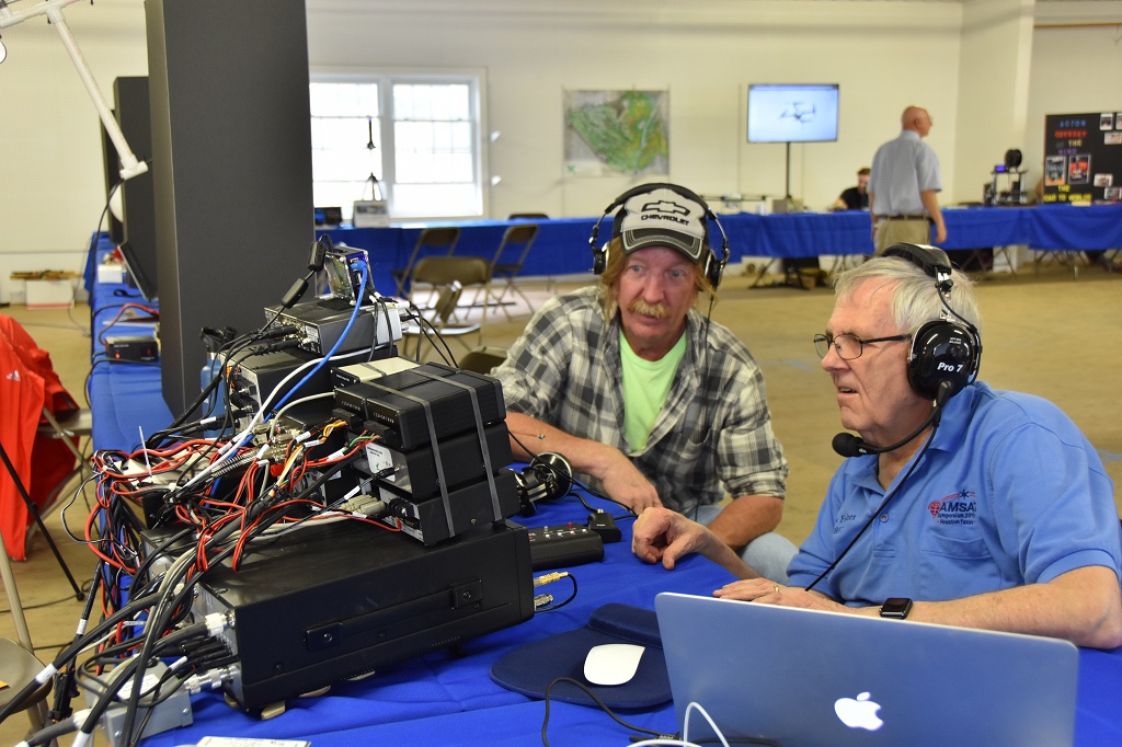
- An HF DXing Display which included two Remotely Operated HF Stations using SDR Technology
- A Mobile HF Communications Display and GOTA
- A Field Day and Emergency Communications Display
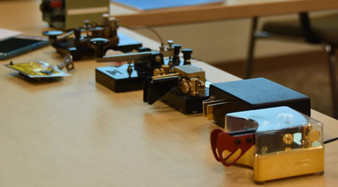
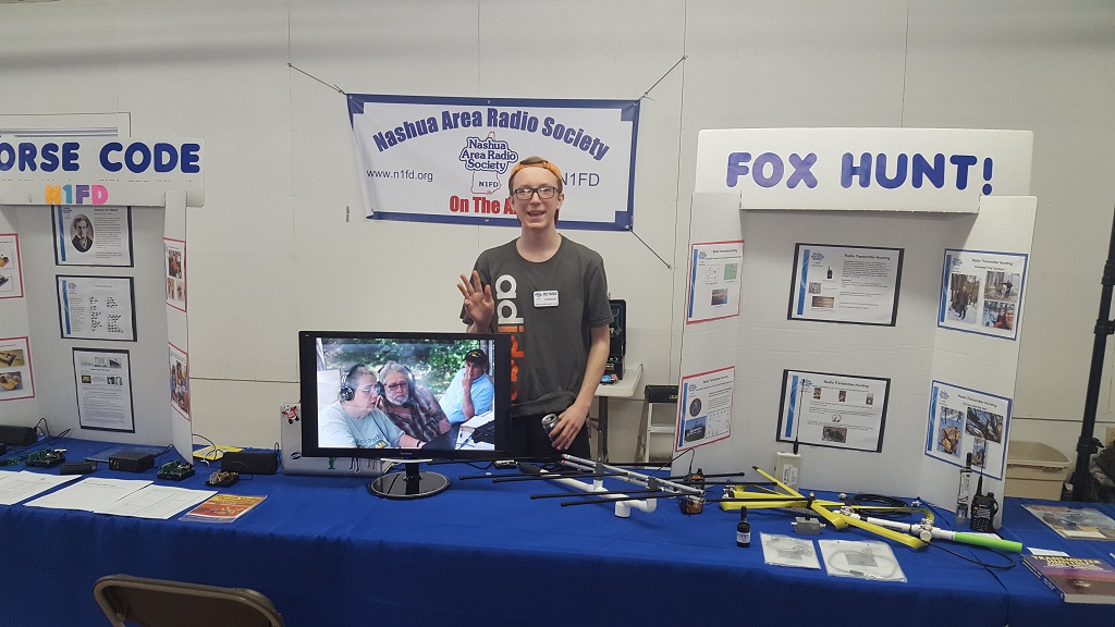
- A Morse Code Communications Display
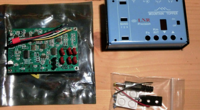
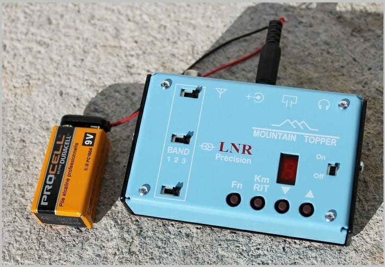
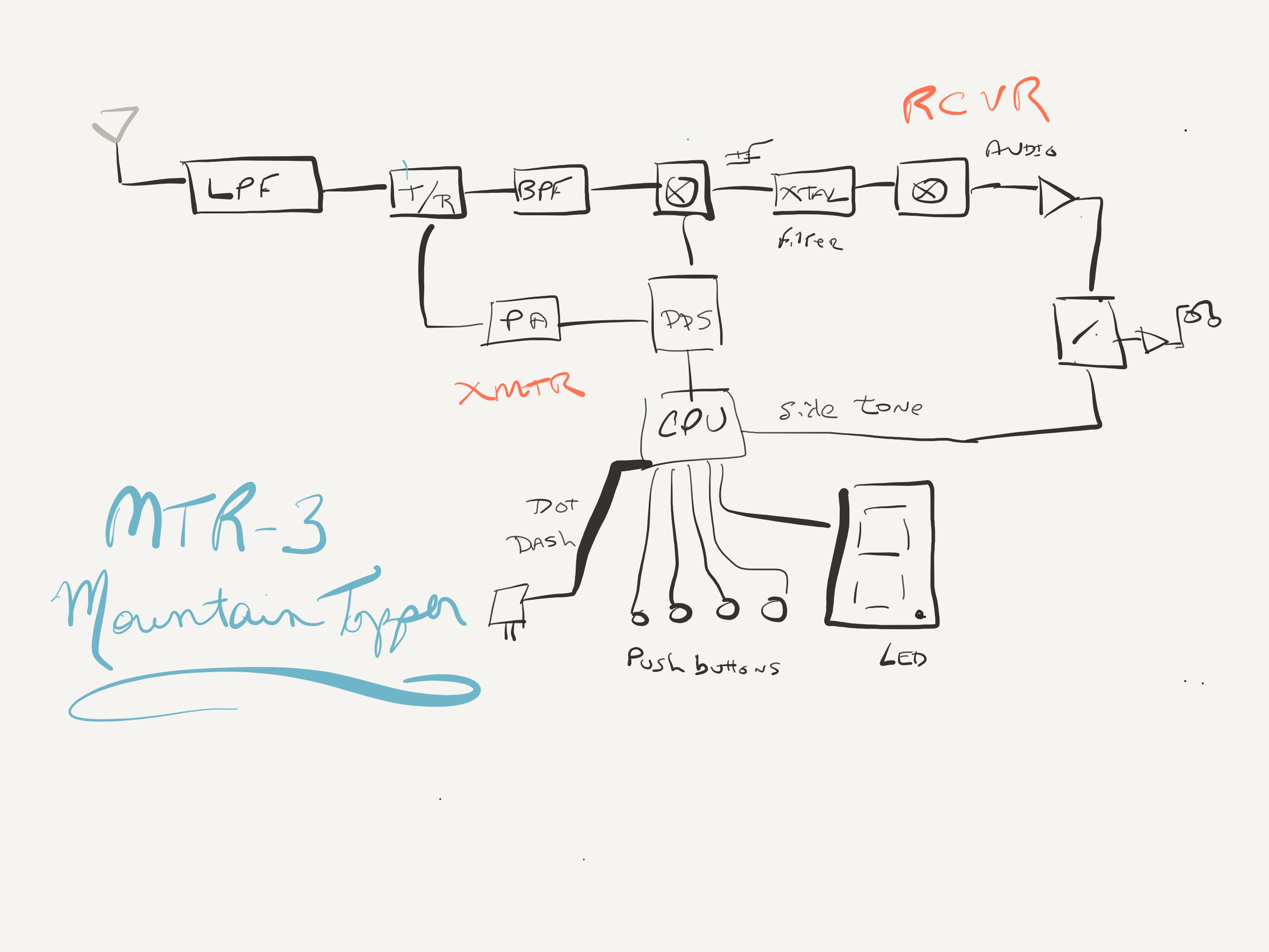
- A Portable Operating/SOTA Display
- A Radio Direction Finding (Fox Hunting) Display
- A Kit Building and Raspberry Pi Computer Display
- An information display about Licensing, Elemering, and Operating Activities at the Nashua Area Radio Society
We were able to secure the N1T Special Event callsign for the event and we used it to make over 450 contacts on a combination of the four GOTA stations that we had at NETT. We should have our NETT Special Event QSL cards back from our printer shortly.

Our GOTA Stations were among the most popular elements at NETT. Burns, WB1FJ ran our satellite GOTA station. He even managed to create a pileup or two as N1T on the birds!
Quite a few folks made satellite contacts using N1T . Also, the satellite station antennas which were located outside the display building were interesting to many folks.
Our Remote HF GOTA Stations featured FlexRadio Maestros and a nice DXing and Station Building Display. Dave, K1DLM and myself, AB1OC made our stations available to support the two HF GOTA setups and NETT.
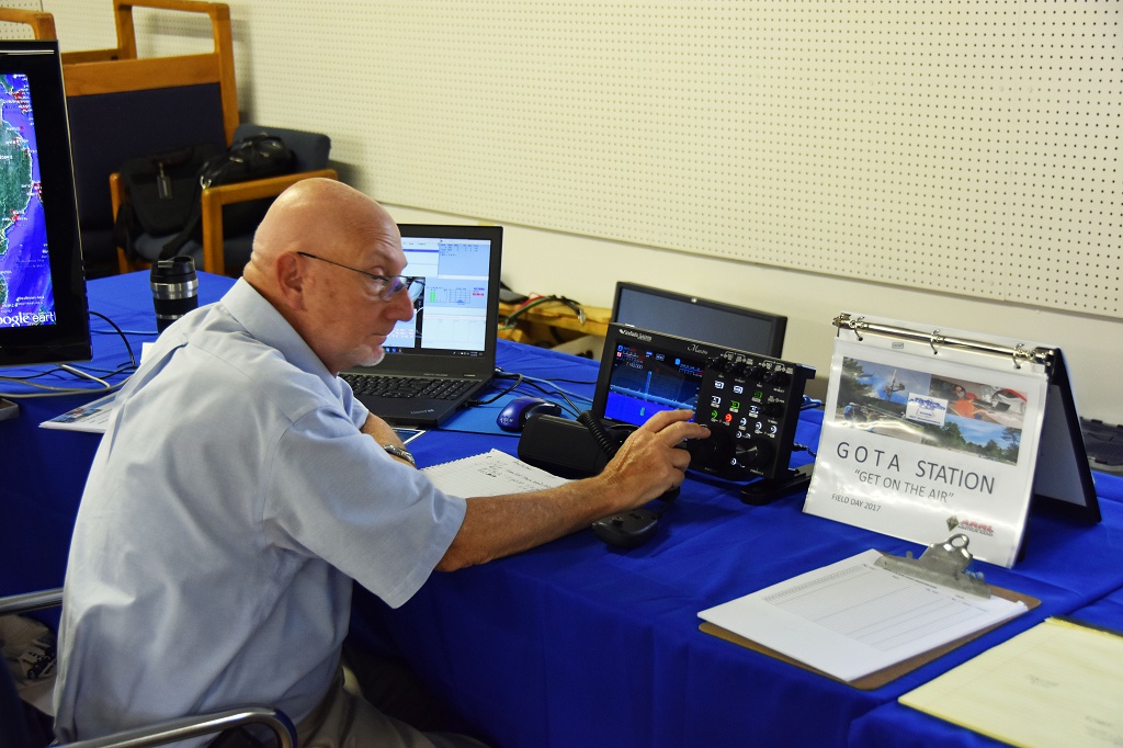
Ira, KC1EMJ helped several young folks to make their first HF contacts and Abby, AB1BY anchored our special event N1T station using the second setup.

The SDR-based remote stations and our Satellite GOTA helped us to demonstrate some of the “Hi-Tech” aspects of Amateur Radio to young people and to all Hams who attended NEAR-Fest. We live streamed our GOTA activities to Facebook so that the folks who worked us could see our operation in real-time.
Tony, KC1DXL hosted our display on High Altitude Balloons (HAB) carrying Amateur Radio. The HAB display got lots of interest from the folks who attended NETT.
Jamey, AC1DC and Connor, KC1GGX put together our displays on Fox Hunting, Morse Code, and portable operating. Their displays provided a great introduction to these activities.
Anita, AB1QB and Tom, AB1NS created a nice display on kit building and Raspberry Pi projects in Amateur Radio. This display was a popular one as well.

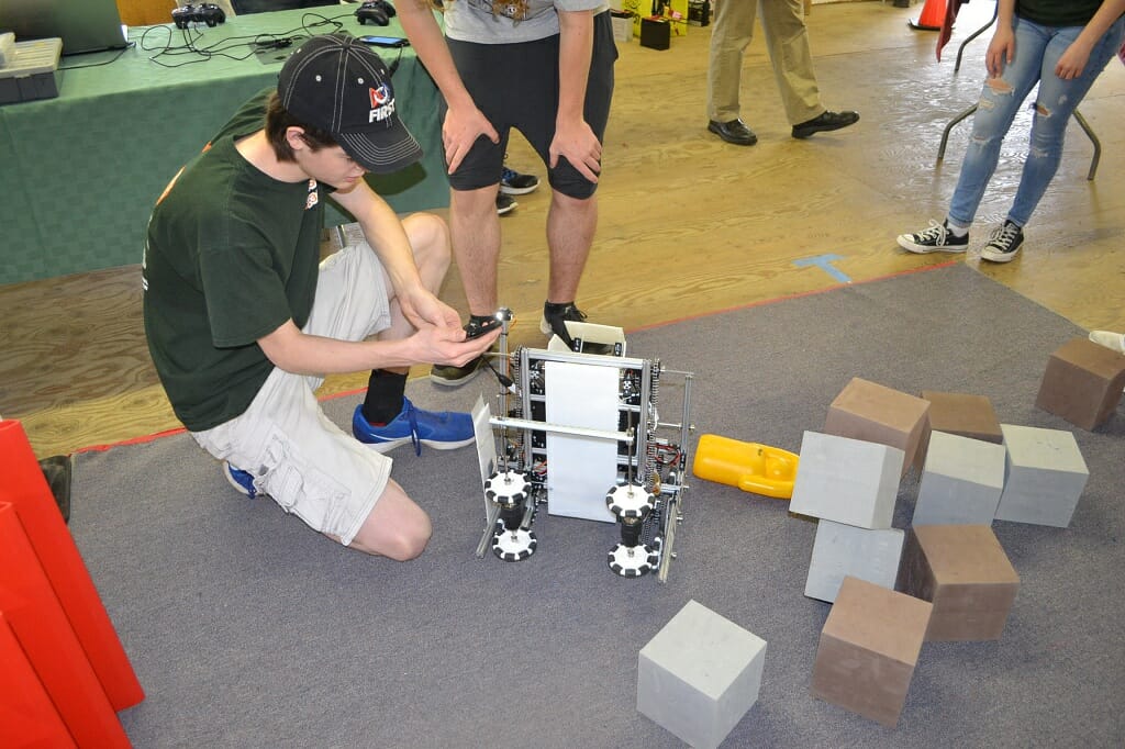
Bill, NE1B also engaged several other groups who provided displays at NETT. The Robotics and Drone were among other popular displays.
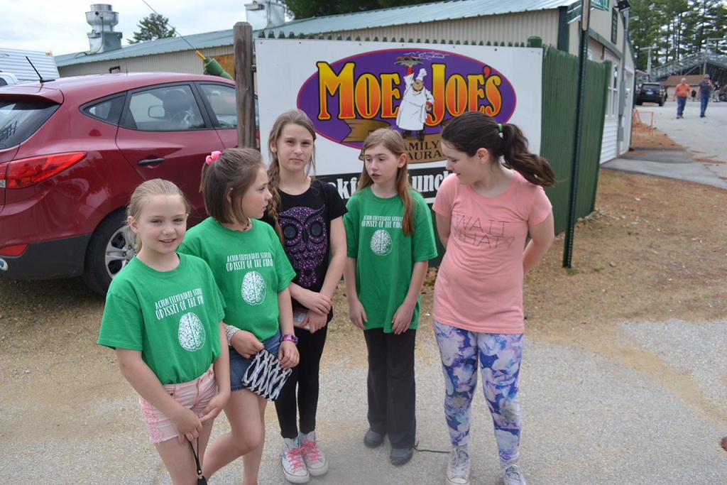
The following photo archive contains some pictures from the event. There are many good memories there.
Many, many members of NARS contributed a great deal of time and energy to making this project a success and I’d like to thank everyone who helped us!! I’d especially like to thank Hamilton, K1HMS, Mike, K1WVO, Craig, N1SFT, Charlie, AB1ZN, Bob, W1OLD, and Dave, K1DLM for their help with this event. Without everyone’s support, the NETT event and our presence there would not have been possible. We are looking forward to replicating the most popular elements from our displays at out Ham Fest events going forward.
Fred, AB1OC