Category Archives: CW and QRP

Articles related to CW and QRP (low-power) operating and equipment. Articles related to learning and using Morse Code are also included here.

Spectral Purity of a QRP Transmitter Driver Amplifier

Introduction

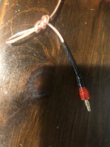
Some months ago, we reported on a commercially available, off-the-shelf 3W MMIC amplifier [1] to be used as part of a transmitter driver with receive bypass [2]. It was our intent to use as many COTS components as possible to simplify and shorten the construction timeline for a 10-band QRP SSB transceiver. An inexpensive amplifier that is widely available through AliExpress [3] is advertised to work from 2 to 700 MHz, which is more than adequate for our requirements (Figure 1. The gain of this amplifier was 45 dB.

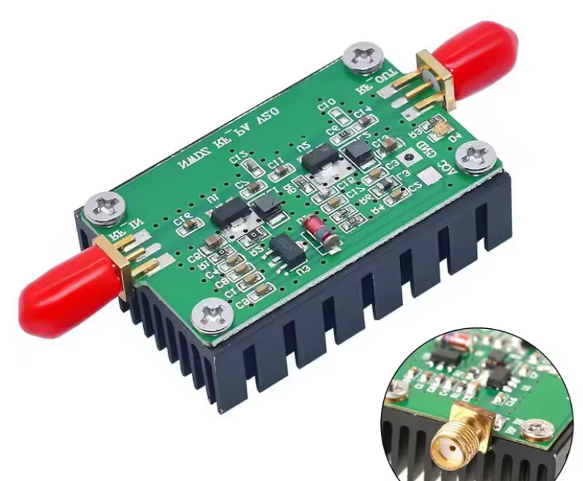
Figure 1. Wideband 3W Shortwave Amplifier. This wideband shortwave amplifier is advertised as being capable of 3W output power. Our plan is to drive it to 1W so that our 10 dB gain power amplifier can be driven to 10W. The 3W MMIC amplifier works from 2 to 700 MHz, which is more than adequate for high-frequency use. The measured gain of the amplifier is 45 dB. Power dissipation is greatly improved by the application of diamond heatsink compound between the circuit board and the heatsink. The amplifier is operated at +9 VDC to reduce its thermal dissipation. Please click on the Figure to open it in a new window.

Since our last report, some changes have been made to the original circuit to reduce its gain, increase its stability, improve its spectral purity, and enhance its receive isolation. The 3W MMIC amplifier is of single-ended construction. Consequently, there is no cancellation of even (or odd) harmonics of the signal being amplified, and it turns out that when operated at +9 VDC, or even +13.8 VDC, the MMIC amplifier is quite nonlinear.

This article discusses all of the circuit improvements. In particular, the spectral purity of the transmitter driver amplifier is demonstrated. Use of the single-ended amplifier requires the addition of another low-pass filter bank [4] between the driver amplifier circuit and the transmitter, in addition to the one that is provided at the transmitter output.

Low Pass Filter Bank

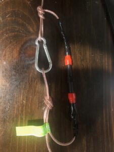
Thanks to Hans Summers, G0UPL, at QRP Labs [5] for providing bare boards so that my original filter bank, consisting of 10 low-pass filters, Figure 2, that employed the Ed Wetherhold (SK), W3NQN, design [6] could be built and tested.

As we will soon demonstrate, an additional low-pass filter bank results in greatly improved spectral purity. Since an additional low-pass filter bank had not yet been built, we have employed the transmitter low-pass filter bank, as required, for measurements in this paper.

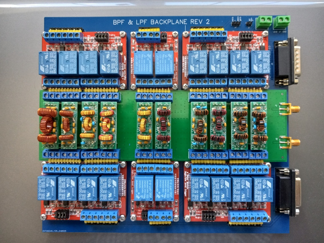
Figure 2. Ten-Band Low Pass Filter Bank on Its Interconnect Backplane. The 40m low-pass filter that was used to process the 7.1 MHz signal is located four filters from the left. All of the filters employ the Ed Wetherhold (SK), W3NQN, design. The bare boards for these filters were obtained from Hans Summers, G0UPL, at QRP Labs. Readily available Arduino relay boards were used throughout. Since these are power relays, the relay contacts are DC-wetted through bias-T’s, not shown, to reduce the contact resistance. The QRP Labs filters employ a single DPDT relay per filter band, whereas my filters employ two separate SPDT relays per band. Please click on the Figure to open it in a new window.

Revised Transmitter Driver With Receive Bypass Schematic
A revised schematic diagram is shown in Figure 3. Changes to the original design [7] include the removal of relay optical isolation for push-to-talk with the deletion of its attendant FET driver, and the addition of relay grounding for the receive bypass path during transmit. An additional relay pair was added to perform the grounding function. A 3 dB attenuator was added to the driver amplifier input to improve the amplifier stability and to reduce its gain. A photo of the completed design with the 3 dB coaxial attenuator installed is shown in Figure 4. If there is sufficient isolation, the 3 dB attenuator will be added to the back of the circuit card. The revised design uses a separate power management circuit board to supply +13.8 VDC to the +9 VDC onboard voltage regulator during transmit. This greatly simplifies the circuit board.

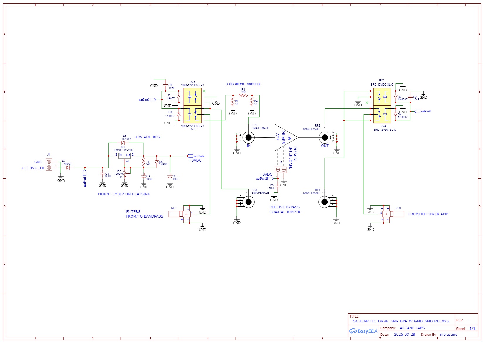
Figure 3. Revised Driver Schematic Diagram. The schematic has been simplified when compared to the previous iteration. The logic input has been removed so that the module may be keyed by the power management module during transmit. The receive bypass path is grounded at both ends during transmit. Power is supplied to the driver amplifier by an LM317 adjustable voltage regulator that receives power from the power management module during transmit. Please click on the Figure to open it in a new window.

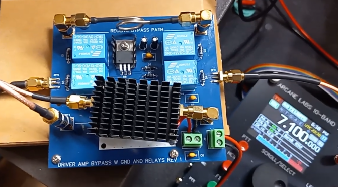
Figure 4. The Completed Driver Amplifier Board As Revised. The black driver amplifier heatsink is visible. The lower relay pair provides the transmit/receive function. The upper relay pair grounds each end of the semi-rigid coax receive path during transmit. The LM317 adjustable regulator regulates +13.8 VDC from the power management module down to +9 VDC for use by the driver amplifier. This reduces the amplifier power dissipation. Please click on the Figure to open it in a new window.

The measured spectrum of the amplified 7.1 MHz signal without low-pass filtering is shown in Figure 5. The amplifier has been driven to 1W. Since the amplifier is single-ended, the even harmonics have not been suppressed, and the 2nd harmonic is barely 10 dB below the carrier. It is evident that this MMIC amplifier is nonlinear.

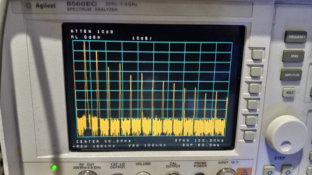
Figure 5. Spectral Purity of a 7.1 MHz Signal Prior to Low Pass Filtering. Even and odd harmonics are visible because the driver is single-ended, not push-pull. A push-pull amplifier would provide some attenuation of the even harmonics but not the odd harmonics. The spectrum analyzer display shows the 7.1 MHz carrier at 0 dBm. Since the spectrum analyzer input is padded by 30 dB, 0 dBm corresponds to 1W. The second harmonic is barely -10 dBc for this drive level. Please click on the Figure to open it in a new window.

The measured spectrum of the amplified 7.1 MHz signal with low-pass filtering is shown in Figure 6. The amplifier drive level was left unchanged from the previous measurement. With the low-pass filter applied to the signal, both the even and odd harmonics have been suppressed by nearly 60 dB.

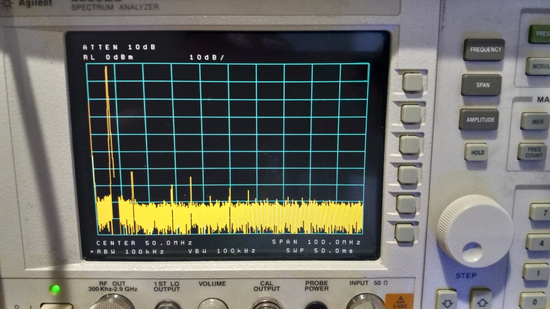
Figure 6. Spectral Purity of a 7.1 MHz Signal After Low Pass Filtering. The even and odd harmonic content of the 7.1 MHz signal has been suppressed by nearly 60 dB. The implication is that the W3NQN 40m low-pass filter is doing a great job of attenuating the 2nd harmonic and higher-order products. About 1 dB of signal attenuation is observed after passing it through the low-pass filter, as one might expect. As in the previous figure, 0 dBm corresponds to 1W due to the presence of a 30 dB pad at the spectrum analyzer input. Please click on the Figure to open it in a new window.

Summary

We have described revisions to the original circuit design that result in a much simpler driver amplifier that retains a receive bypass function. The revised circuit is keyed from the power management module on transmit so that it does not have to be keyed directly from push-to-talk.

The spectral purity of the amplified signal before and after low-pass filtering has been demonstrated. Higher order harmonics are attenuated by nearly 60 dB by Ed Wetherhold, W3NQN, low-pass filters.

The low-pass filter bank that was used for spectral evaluation is at the transmitter output. Consequently, another low-pass filter kit has been ordered from QRP Labs that will cover 5 of the 10 bands. Another kit will be ordered at a later date to cover the remaining 5 bands. Since these low-pass filters come without an integral transistor interface for microprocessor I/O, one will have to be built.

A short YouTube video [8] of a test may be viewed at https://youtu.be/nTQk9CR1W9w

References

[1] 2 MHz-700 MHZ 3W HF VHF UHF FM Transmitter RF Power Amplifier For Radio https://www.aliexpress.us/item/3256807249993037.html?spm=a2g0o.order_list.order_list_main.25.1adb1802la12vX&gatewayAdapt=glo2usa

[2] Blustine, Martin, RF Driver Amplifier With Receive Bypass, N1FD, Nov. 1, 2025. https://www.n1fd.org/2025/11/01/rf-driver-amplifier/

[3] AliExpress, op. cit.

[4] QRP Labs, Ultimate Relay-Switched LPF Kit, https://qrp-labs.com/ultimatelpf.html

[5] QRP Labs, Low Pass Filter Kit, https://qrp-labs.com/lpfkit.html

[6] Wetherhold, Ed, W3NQN, Second-Harmonic Optimized Low-Pass Filters, QST, Feb. 1999, pp. 44 – 46.

https://www.arrl.org/files/file/Technology/tis/info/pdf/9902044.pdf

[7] Blustine, Martin, op. cit.

[8] YouTube Test Video, https://youtu.be/nTQk9CR1W9w

Disclaimers

This circuit design is provided for informational and educational purposes only and is supplied “as is” and without warranties of any kind, express, implied, or statutory. No representations or warranties are made regarding the accuracy, adequacy, completeness, legality, reliability, or usefulness of this information, either in isolation or in the aggregate. This circuit design may contain links to or information based on external sources or third-party content. Endorsement and responsibility for the accuracy or reliability of such third-party information or for the content of any linked websites are not taken.

N1FD Winter Field Day 2026

The Nashua Area Radio Society (N1FD) successfully completed Winter Field Day 2026, operating on January 24–25 under some of the harshest winter conditions we’ve experienced in recent years. Bitter cold persisted throughout the weekend, followed by a snowstorm on Sunday afternoon, yet the club achieved all planned multipliers and delivered a strong overall result.

N1FD operated as Class 2H, with all stations located indoors at the QTH of Fred Kemmerer, AB1OC, and Anita Kemmerer, AB1QB. Antennas were deployed outdoors, allowing operators to remain warm, safe, and focused while fully meeting the operating and technical challenges of Winter Field Day.

N1FD Team Putting Up the Wire Antennas in the Prep Session on 12/20

Preparation Made the Difference

Winter Field Day success was the result of careful planning and coordination in the weeks leading up to the event. The club focused on targeting specific band and mode multipliers, ensuring coverage across HF, VHF, and UHF, coordinating operator schedules and operating strategies, and verifying station readiness and antenna performance.

That preparation paid off, allowing N1FD to methodically work bands and modes and complete every planned multiplier without last-minute pressure.

QSO and Band Results

During the weekend, N1FD logged:

BandModeQSOsPts
160 mCW55110
80 mLSB2020
40 mLSB8181
20 mPSK3112
20 mUSB445445
15 mUSB337337
10 mUSB8181
6 mUSB33
2 mFM33
1.2 mFM33
70 cmFM33
33 cmFM33
23 cmFM33
TotalAll10381094

1,038 total QSOs
1,094 total QSO points
28 total multipliers
Based on these results, N1FD’s estimated final score was:

1,094 QSO points × 28 multipliers = 31,726 points

The strongest activity came from 20 meters (USB) and 15 meters (USB), with solid participation across 40 meters, 80 meters (CW), digital modes, and successful contacts on VHF and UHF, all of which were critical to completing the multiplier plan.

Multipliers Achieved

A major objective for Winter Field Day 2026 was to intentionally pursue as many multipliers as possible through planning and disciplined operating. N1FD successfully completed every multiplier we set out to achieve, resulting in a total multiplier of 29X, including the 1X multiplier added for participation.

The following multipliers were earned during the event.

N1FD Multipliers Achieved

Completing the full multiplier set was a direct result of advance planning, operator coordination, and flexibility throughout the weekend.

Fred AB1OC Working on Multipliers while Anthony KC1DXL Operates SSB

Operators on the Air

The following members operated under the N1FD callsign during Winter Field Day:

Operators rotated across bands and modes to keep stations active and productive throughout the event.

HTs Covering 2m - 23cm
HTs Covering 2m – 23cm

VHF Rover Participation

In addition to the fixed indoor stations, three N1FD members participated as VHF Rovers, helping us to achieve the 12-band multiplier.

Their rover operations added an important mobile element to N1FD’s Winter Field Day effort.

Special Thanks

Special thanks go to Joe Luszcz, AC1LN, and Brian Quick, W1XMM, who installed the wire antennas on Friday, January 23rd, working outdoors in very cold weather to ensure the stations were fully operational before the event began.

Additional recognition goes to Fred Kemmerer, AB1OC, who spent many long hours preparing the station, testing equipment, and resolving technical details ahead of Winter Field Day. His dedication was critical to the smooth operation and success of the weekend.

We would also like to thank Brian Quick, W1XMM, for his leadership in planning and coordinating Winter Field Day 2026 in his role as Field Day Chairman. His organization and preparation were instrumental in helping the club meet its operating and multiplier goals.

Special thanks to Dave Cherkus, N1AI, for operating 160-meter CW, helping N1FD make effective use of the low bands during challenging winter conditions.

Thank you to Dave Berardinelli, K1BER, for leading and coordinating the VHF Rover effort, which played an important role in expanding our band coverage and multiplier success.

Finally, thank you to all of the operators who participated throughout the weekend. Your time, flexibility, and teamwork made this Winter Field Day a success.

A Successful Winter Operation

Winter Field Day 2026 once again demonstrated what N1FD does best: strong planning, teamwork, and adaptability, even under challenging winter conditions. Operating indoors allowed the club to stay safe and effective while still delivering excellent on-air results.

Thank you to everyone who planned, set up, operated, and supported this effort. We look forward to building on this success for future Field Days and operating events.

QRP In the Field

Given that Summer is in full swing and SOTA/POTA activating or hunting seems to be on everyone’s mind, I figured that an article on QRP portable operation was in order. One disclaimer, however… I am not a vastly experienced QRP portable op… I’ve dabbled in it and seen lots of YouTube vids (I guess that does make me kind of an expert)… and I do operate QRP from time to time. And, like a good pack rat… I have collected a few QRP rigs and their associated bling that I like to use.

A Little Background

SOTA/POTA

If you’re not familiar with SOTA, it stands for Summits On The Air, a “program” in which Hams go to summits and operate (It is kind of like the stricter, more formal cousin to the seemingly better known POTA or Parks On The Air). The SOTA web site at SOTA.org.uk describes SOTA as “an award scheme for radio amateurs that encourages portable operation in mountainous areas”.  Both POTA and SOTA are typically done QRP, as QRP gear lends itself nicely to these activities… it’s lighter and more portable than an Icom 7300 or Yaesu FTdx10.

Although many SOTA operators spend all kinds of time trying to lighten their packs with the smallest setups possible… I am not one of them. I always overpack for any hiking trip (or at least my traveling companions complain that I do).  As far as radio is concerned, when I am out “portable”, I typically operate out of my truck so weight is not an issue, so all my stuff is gonna be heavier. Also, I like my summits to be accessible via car… not that I am lazy (although my wife may disagree with that statement), it just happens that a nice hike generally takes me a while and seriously cuts into my operating time. That being said, I do have a few fairly light rigs if I really want to slim things down.

QRP

I think everyone is familiar with QRP operating, but if not… QRP refers to the use of low power when transmitting, typically five watts or less. QRPp is used to describe sub 1 watt operation (I am not that hardcore, nor am I a masochist, so I generally stick with 5 watts). Despite the reduced power, QRP is actually a lot of fun and has many advantages over higher-powered setups (especially for operating in the field).

Why Go QRP?

Altoids Tim QRP
Altoids Tim QRP

One of the main benefits of QRP is its portability. Because the equipment required to transmit at low power is generally small and lightweight, it can easily be taken to the field (and a side benefit is it can easily be hidden from your spouse). With QRP gear, it’s possible to operate from remote or rugged locations that might not be accessible with larger, more complex setups.

Another advantage of QRP is its simplicity. QRP equipment is generally less complex than QRO setups, which means that it’s generally easier to set up and use (as well as easier to afford). This makes it a great choice for field operation too. The transceivers are smaller and generally less expensive, tuners (if you use them) are smaller, and there are a host of CW keys that cater to the lightweight QRP crowd. These little gems can be as light as a few ounces. Since I don’t have the greatest dexterity in the world, I use a fairly large and hefty key… it weighs almost as much as each of my QRP rigs! Despite its size and weight, it fits nicely in my truck.

Despite its lower power output, QRP can still provide excellent performance. I have noticed, in my completely non-scientific testing, that I have not yet failed to complete a single QRP QSO. Now mind you, it may, and generally does, take me longer to complete a QRP QSO than it does to complete one at 100, 500 or 1000 watts. Stands to reason. But, it has never failed me. However, I generally only operate either CW or FT8 when QRP, rarely SSB. So, keep that in mind.

You do have to be patient though, and be mindful of who you are trying to QSO with. If you’re just on the air for some casual contacts or are activating a park or summit, you will likely do well and have fun. If you are trying to work a DX’pedition to a top 10 most wanted country, you might have some trouble making the QSO and experience what I once heard a Ham say about QRP… “with reduced power comes great frustration”. But, with the right attitude, QRP can be a lot of fun! QRP can be especially satisfying for those of us who enjoy the challenge of making long-distance contacts with minimal power… and it’s also fun to explain to your spouse the concept of dollars/mile when you want to pick up that new, “inexpensive” QRP gear.

Gear and Such

Obviously, when operating QRP in the field, you’ll not be bringing along your tower and yagis, or likely even your full-size multiband wire antennas. QRP operation in the field is generally about simplicity, ease of setup, and ensuring a low frustration quotient. Often wire verticals with a few radials are used in conjunction with a lightweight fiberglass mast, or, what seems to be more popular, is the use of End Fed Half Wave antennas (commonly called EFHW antennas). This is what I use. It is typically a ½ wavelength radiator connected to the radio, usually with a 9:1 or 49:1 transformer. For the more popular QRP bands (20, 30, and 40 Meters), it is a very manageable antenna.

So this is a good time to talk about gear… that’s always fun, talking about gear (not as much fun as building or buying it and then using it though). Depending on what you want to do with QRP and where you want to operate, gear considerations can range from just a transceiver to an entire station.

For those that want to operate QRP from home, you likely have what you need already! Most HF radios can be dialed down to 5W or less. BINGO… you are running a QRP station. For those of us that want to bring our stations to the field, it is unlikely that we’ll drag our YaeComWoodCraftTec HF rigs (get it? Yaesu, Icom, Kenwood, Elecraft, and Ten Tec) to a campground, state park, or summit. So what’s a Ham to do? I am glad you asked…

Transceivers

Options

QRP transceivers can range in price from $14 (for a single frequency Pixie kit) to several grand for a new Elecraft rig. I advise staying away from the really cheap rigs though, as their performance is commensurate with their price (and they drive the frustration quotient wayyyy up). Many QRP rigs come in kit form, but if kit building is not your thing, there are many that you can buy pre-built. As well, most QRP rigs are either single band or limited to a subset of the HF range… typically 20-80M. Although, the more expensive rigs will cover the entire HF spectrum and even 6M in some cases. 20, 30, and 40 meters are the most popular QRP bands, and most QRP gear will operate there.

Manufacturers

Elecraft has made and continues to make some very popular QRP rigs (such as the KX-1, KX-2, and KX-3), Yaesu has their FT-818 and 819 rigs, Icom has their IC-703 and current IC-705 rigs, LNR Precision makes the Mountain Topper line of QRP rigs, and MFJ made their Cub line of QRP rigs which you can sometimes find on Ebay, DL2MAN & PE1NNZ offer their (tr)uSDX line of SDR QRP rigs, and Xiegu makes some nice rigs including their G90 and X5105. There are literally hundreds of QRP rigs out there from dozens of manufacturers… Heathkit, Oak Hills Research, NorCal Radio, QRP Labs, Small Wonder Labs, Index Laboratories, etc. The list goes on and on.

Due Diligence

Unless you like being surprised though, do your research before buying a QRP rig. YouTube has lots of great vids on QRP transceivers. Google “YouTube Ham Radio Crash Course QRP”, “You Tube K4SWL QRP” “YouTube review <insert QRP rig here>”. eHam also has a product review forum that can be very helpful in making gear decisions, Check them out at Eham.net.

My Favorites

I have a number of QRP transceivers (none were particularly expensive) but my favorites are the (tr)uSDX, and the LNR Precision FX-2, as both are very portable and have features that I like. I also have an MFJ Cub for 30 meters, which I like but it takes ~30 minutes to warm up to become frequency stable… not a good field radio.

(tr)uSDX SDR QRP Rig

The (tr)uSDX is a multi-band, multi-mode rig covering 20-80 meters with a maximum of 5w out. It operates SSB, AM, CW, and digital (with the right interface). It has a lot of really slick features for a sub $200 HF rig.


LNR Precision FX-2
LNR Precision FX-2

The FX-2 (which is no longer made) is a 30 and 40 meter CW only rig with up to 5w out. It is built like a tank with some cool features as well and cost me $70.  I bet you already know a Ham who has their own favorite QRP rigs they’d love to tell you about!

Power Sources

Batteries are the most likely power source for QRP in the field. While many of the more expensive QRP rigs have internal batteries, most use an external power source. You can use literally any battery that provides the right voltage and current, and most QRP rigs operate anywhere from 8 to 12v, with reduced power below 12v, and draw less than 1 amp on TX. A very popular external battery type used by many QRP ops today are rechargable Lithium Iron Phosphate (aka LiFePO) batteries. They are extremely light, very portable, and perform exceptionally well. A nice accessory to your LiFePO battery is a solar charger. If you plan to spend lots of time in the field, that may be a worthwhile investment. I have found Amazon to be a great source for LiFePO batteries.

Keys

CW Morse Double Paddle

If you are a CW op, I am guessing you are very particular aboutyour keys (aren’t we all). I am a Bencher guy… since I got my ticket, I have used only Bencher Iambic paddles at my station… but they are really big, really heavy, and a pain in the neck to carry around for portable operation. Although I don’t own any, I know that Vibroplex bugs are the same, and many straight keys are a bit cumbersome too (although not as much as bugs or “traditional” paddles).

There are a number of places to get small, lightweight keys for field use. Google it, and you’ll get some options. But I’d like to save you some time (cuz I am a nice guy). Check out CW Morse and have a look at their line of keys. I have their double paddle with a base, and a Camel Back straight key. Both are made very well, and a joy to use… and they fit nicely in my truck. Are there smaller, lighter-weight options out there from them and others? Yep. But I really like and recommend these.

Antennas

QRP Guys No Tune EFHW Transformer

Here’s where the sky is the limit (pardon the pun… I couldn’t help it). QRP antennas run the gamut from loops, to horizontal wires, to verticals, to portable beams. In general however, portability and ease of deployment are key to success in the field. That is what makes the EFHW such a popular QRP field antenna.

EFHW’s are very easy to build and if done right, don’t require a tuner (and to make it even easier, you can buy the transformer in a nice kit). QRPGuys.com sells a bunch of QRP EFHW transformer kits. I have the 10-80m no tune kit. You should check them out . If you are only interested in operating on one or two bands, cutting elements for each band makes sense. But what if you want to operate anywhere from 10-80 meters? Cutting and carrying elements for all of those bands is tiresome, cumbersome, and unnecessary. Enter the “linked dipole” concept for an EFHW antenna.

Linked EFHW

What is a linked dipole? I am glad you asked… according to VK7BEN, a linked dipole “provide[s] the benefit of creating a single-wire antenna that is resonant on multiple bands without a tuner by “linking” together lengths of wire with clips.”. However, I use banana connectors and small carabiners on my linked EFHW. I also found that 18-22 gauge speaker wire works really well for portable EFHW elements.

Building a Linked EFHW

Here’s how to build my version of the linked EFHW.

  1. Determine the full element length for each band you want to work.
  2. Cut the element for the highest band you want to operate (i.e. 20M) at it’s full length.
  3. Next determine the difference between the full length for the next highest band and the previous band (i.e. 30M – 20M).
  4. Then cut an element for that length.

Do this for each band you want to work.

For example, if you want an antenna for 20-40M, here’s what you would do:

  • 20M full length: 28’ 8”
  • 30M full length: 42’ 6”
  • 40M full length: 61’ 6”
  1. Cut an element to 28’ 8” (this is your 20M or “base” element)
  2. Cut an element for the difference between 20 and 30M (13’ 10”), this will be your 30M “linked” element
  3. Cut an element for the difference between 30 and 40M (19’), this will be your 40M “linked” element

I soldered a small ring connector to one end of the 20M element to attach to the QRP Guys transformer kit at the post and wing nut.

20 Meter EFHW Post Connection
20M EFHW Post Connection

On the other end, I made a small loop by tying the antenna back on itself, and then attached a male banana connector to the very end.

Element End
Element End

I did the same to each end of the 30M element and to one end of the 40M element too. To the other end of the 40M element I simply made the loop, but did not add the banana connector.  This is where I attach the “hoist rope” for getting the antenna into the trees.

I have 150 feet of 1/4” line that I use to hoist the antenna into the trees. To one end, I attached a light carabiner.

Using the Linked EFHW

To operate 20M, I simply attach the 20M element to the transformer using the ring connector. Then I attach the carabiner at the end of the hoist rope to the looped end of the 20M element, and pull it up. If I want to operate 30M, I use a female / female barrel connector to electrically attach the 30M linked element to the 20M element. A light carabiner physically connects the two elements at the loops. This provides strain relief for the banana connectors..

Element Connection Point

For 40M, I attach the 40M linked element to the end of the 30M element (which is attached to the 20M element) in the same way and connect the hoist rope to the antenna with a carabiner.

There are many ways to construct a linked antenna. I like this design because, unlike traditional linked dipole designs, which use a “trail line” to deploy all of the elements at once having a length equal to the longest band element, this allows me to only deploy the elements that I need, making antenna deployment overall simpler IMO. I happen to like simple, it is less taxing on my brain.

As with any antenna, resonance can be affected by many factors, but I did not find any impact to the resonance of the elements by tying them back on themselves for the end loops.

Antenna Tuner

MFJ 9201 QRP Antenna Tuner

While it is best to not need or use an antenna tuner, especially when running QRP power levels, sometimes it cannot be helped. Unless your rig has an internal antenna tuner, there are really two options for tuners… automatic or manual. LDG makes some nice auto tuners and one specifically for QRP, the Z-817. Personally, I find external auto-tuners kind of pricey for dragging them out to the field, plus it is one more thing requiring a battery. Although I never want to have to use it, in case I do need one, I keep an MFJ-9201 manual tuner in my kit. The key for tuners is get a small, light-weight one.  Make sure, if it is an auto tuner, that your radio can provide the needed power to activate it. Some auto-tuners will not activate below 5W.

Computer

Who needs a computer in the field! Well, if you want to work FT8 from that shiny new QRP rig, you do. Also, I find logging on a computer to be much easier than doing so on paper. No need to re-enter it all into my log at home when I get back. Plus, my handwriting is atrocious, and often, even I can’t decipher what it says, so I save myself the trouble.

Really, any portable computer will work for logging. From Apple and Android phones, to tablets, to Windows laptops, to Linux devices. As long as they have decent battery life, and some logging software available for them, they should work. I use an older Lenovo Chromebook that I converted to Linux, and log with CQR log. When I get home, I export to an ADI file and import the QSO’s into my home logging software. Because it is a tablet with an O/S that supports WSJT-X, the Lenovo also has the benefit of allowing me to work digital modes such as FT8 as well.

One thing to keep in mind though, paper logs are easy to read in direct sunlight; not so much for many device screens (ask me how I know).

Packs

Now that you have that sweet QRP field kit, how do you get it where you’re going? Well, this is the topic of hours and hours of YouTube videos. Backpacks are the most reasonable answer if you’re going into the bush, but, if you are like me and going into the bush means driving to a place with trees, you might want to consider something else.

I’ve seen many cool QRP field setups carried in Pelican cases, or the less expensive Apache cases from Harbor Freight. One benefit to them is that your stuff is well protected if you tend to drop things (again… ask me how I know). In addition to Apache cases, I also use a small “range” bag that can be found at most sporting goods stores or online. It has lots of pockets and is easily carried. It also fits nicely in my truck when I am going into the bush.

If you are a backpack person, there are literally dozens of options. If you need to kill a week or so of time,  Google “Best backpack for QRP” or “Best backpack for SOTA/POTA”.

There You Have It

That’s the 411 of QRP and building out a basic QRP field kit. Of course, your kit can be anything from minimalist to extravagant, but, you don’t need a lot of gear or money to have some QRP fun. The key, especially if you are interested in going outdoors with your gear, is simply to do it. QRP gear is the perfect companion to a day at the park (or even a few hours grabbed at the end of the work-day).

Operating QRP can be a lot of fun simply because it’s a challenge. In my opinion, operating QRP successfully, builds out a set of skills and techniques that will also make you a better QRO operator. And, there is certainly a sense of accomplishment that comes from successfully communicating with others using minimal power.

Whether you plan to operate, watch and learn, or just hang out and socialize; I certainly hope to see you at the upcoming NARS SOTA activations. Unless I have to travel, I plan to be there and exercise my field kit. Of course, I’ll be driving up.


Radio Amateurs Developing Skills Worldwide