The 2019 Thirteen Colonies Special Event begins today! There are stations in each of the states that grew from the original Thirteen Colonies plus two bonus stations – WM3PEN in Philadelphia, PA an…
K2K New Hamshire will be operating all modes on 160m – 6m (except for 60m) and on Satellites as well. We’ll have a QRP station (K2K/QRP) as well.
The 2019 Thirteen Colonies Special Event begins today. Get on the air and work all Thirteen Colonies as K2A – K2M and don’t forget the two bonus stations – WM3PEN and GB13COL. Have fun!
The RockMite is a very small, but complete, transceiver. We covered most of the radio’s components in the first three parts, but it is worth reviewing. Instead of just rehashing the previous text, we should explore those ideas from a different angle.
A great place to start any investigation is asking the question, “What problem are we trying to solve?” This is a very relevant question when dissecting a radio. Answering questions like, “What does this particular thing do?” and “Why is this here?” helps us not only understand the results better, but I contend they help us remember the answers better, too.
In part one we explored the receiver. The problem to be solved there was “How do I take energy at radio frequencies and turn them into sounds my ears can hear?” We did that with an oscillator (discussed later) and a mixer, combining two frequencies to produce the four frequencies from two A and B:A, B, A+B, and A-B. It was the A-B (the free-running oscillator and the received signal) that combined to result in a frequency in the audible range.
In part two we looked at the user interface (UI) of the device, what little of it there is. There were a couple of points there, however, including problems solved like “Can I have an iambic keyer? and “How can we operate this radio on multiple frequencies?” and “How do we turn on the transmitter?” All of these things were controlled by the small Microchip PIC processor.
In part three we looked at the oscillator and saw how the output of the oscillator fed into the mixer for the receiver, and how it also fed forward into the transmitter section of the radio to be discussed today. The magic of the varactor tuning diode gave us a second frequency for the radio that could be directly controlled by the simple microprocessor.
In this last article on the RockMite we will look at the final stages of the transmitter, and specifically the filtering between the transmitter and the antenna.
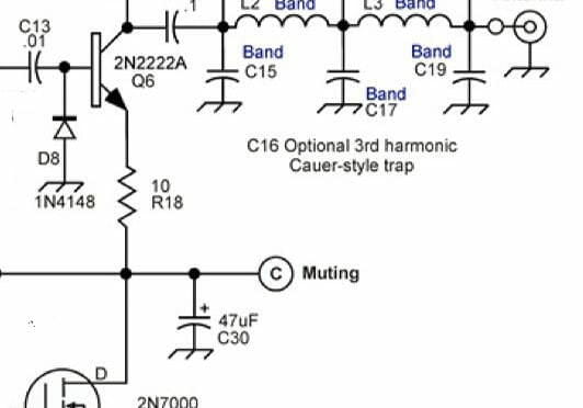
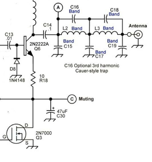
The Schematic
Below is a schematic for the RockMite that we’ve been using for these articles.
Schematic for the RockMite transceiver (from QRPMe.com)
The particular part of the schematic we are interested in today is highlighted in the following:
We will discuss each part in turn.
Final Amplifier Stage
The final amplifier Q6 in the RockMite is the versatile and ubiquitous 2N2222A in the nice metal can. We put a heat-sink on the can to keep the transistor cool. The transistor amplifier is fed by a capacitive couple to the first stage amplifier Q5. (Q5 is fed by the oscillator.)
Q6 is connected to Vdc via an inductor, and to ground when the switching transistor Q3 is turned on. The Q3 transistor is connected to the transmit-receive (T-R) line on the PIC processor and when it powers the gate a connection is made through Q3 to ground, activating Q6. When Q3 is not turned on Q6 is quiet and the receiver can operate.
Filtering
Again, we should begin a discussion with “What problem are we trying to solve?” The final amplifier Q6 is solving the problem of “How do we get our signal amplified to a reasonable level?” Q6 does a nice job with this and the RockMite puts out somewhere around a half-of-a-Watt of power.
But, the trouble with generating signals like this is we also generate unwanted signals as harmonics. So, the question becomes, “How can we pass through the signal we want, but none of the harmonics?”
A good answer to that question is a low-pass filter. Filter design is far beyond the scope of this brief article, but it might be useful to walk through a simple filter design exercise.
I went to rf-tools.com and found a filter design tool. I’ve captured a screen-shot of my work creating a low-pass filter for a 40m radio. That appears below.
I used some straight-forward parameters for our filter. I want the cutoff frequency to be above 40m so I chose 8 MHz. I left the Passband Ripple (dB) to the value defaulted by the program. And, I left the impedance in-and-out be 50 Ohms. Finally, I told it to choose values that exist in parts catalogs (“standard” values).
The program generated the schematic near the top, and chose appropriate values for the parts to create the intended filter. The response curve of the filter appears in the graph below the schematic.
Examine the schematic for the transmitter section, especially the components just before the antenna connection. We have five parts of interest L2, L3, C15, C17, and C19. (Note that C16 and C18 are not populated and are reserved for future versions of the kit.) These five components are the low-pass filter for the radio. The specific parts to be used depend upon the band we want. The values for a 40m band radio are:
L2 and L3: 1 µH
C15, C19: 470 pF
C17: 1000 pF
If you check, these values from the RockMite design are very close to the values selected by our filter design program. (The designers of the RockMite, K1SWL and W1REX, are likely a lot smarter about filter design than I am, so we’ll take it on faith that their value selections are better.) The differences are small: L2 and L4 have 1.0 µH in the RockMite design; the corresponding parts in our designed filter are 1.3 µH. C15 and C19 in the RockMite design match perfectly to the corresponding parts in our filter’s design. And C17 is 1000 pF in the RockMite design, and 820 pF in our filter design. These are all very close.
The “Insertion Loss and Return Loss” graph for our filter’s design estimates the filter’s performance. The blue line that runs from upper left to the lower right corner shows the loss for a given frequency. Our first harmonic will be at 14 MHz. The line intersects 14 MHz at 27.6 dB, meaning any outputted frequency entering the filter will be diminished by 27.6 dB. Our second harmonic at 21 MHz is reduced by nearly 48 dB.
Why do we care about keeping harmonics down?
The FCC demands it.
97.307 Emission standards.
(d) For transmitters installed after January 1, 2003, the mean power of any spurious emission from a station transmitter or external RF power amplifier transmitting on a frequency below 30 MHz must be at least 43 dB below the mean power of the fundamental emission. For transmitters installed on or before January 1, 2003, the mean power of any spurious emission from a station transmitter or external RF power amplifier transmitting on a frequency below 30 MHz must not exceed 50 mW and must be at least 40 dB below the mean power of the fundamental emission. For a transmitter of mean power less than 5 W installed on or before January 1, 2003, the attenuation must be at least 30 dB. A transmitter built before April 15, 1977, or first marketed before January 1, 1978, is exempt from this requirement.
So, just guessing, the values in the RockMite’s design for the components probably make the roll-off just a little steeper. Our circuit designed in the on the RF Tools website did a good job, though. If we were really worried about it we could have put another few components in. Check out the following 7th order low-pass filter. At our first harmonic 14 MHz, our harmonics are down over 47 dB. That more than satisfies the FCC.
Wrapping Up
One of the things I love about QRP and low-power operating is I can (almost) understand all the components in the radio. I know what most things do, and I even understand why most things work. I’m still learning.
This is the last installment of the RockMite teardown. I hope you’ve enjoyed it!
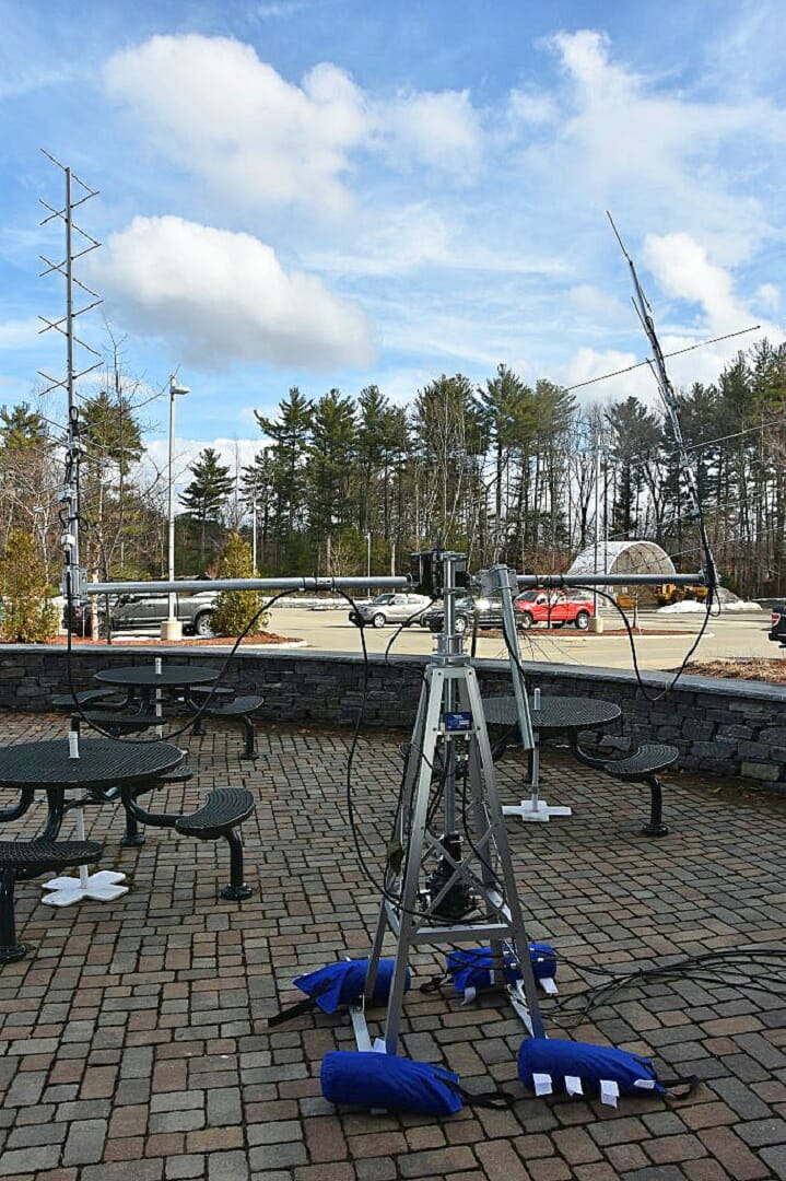
We will have lots of great activities for folks who are interested in operating on the VHF and above bands at Field Day 2019. Here are some of the activities that we’ll be doing:
Satellite Contacts using a Portable Computer Controlled Satellite Stations
Weak Signal SSB, CW, and FT8 Contacts on 6m, 2m, and 70cm
Fox Hunting using Radio Direction Finding (RDF) to find hidden 2m Radio Transmitters
Satellite Station, VHF+ Station, and Fox Hunting Training
Satellites at Field Day
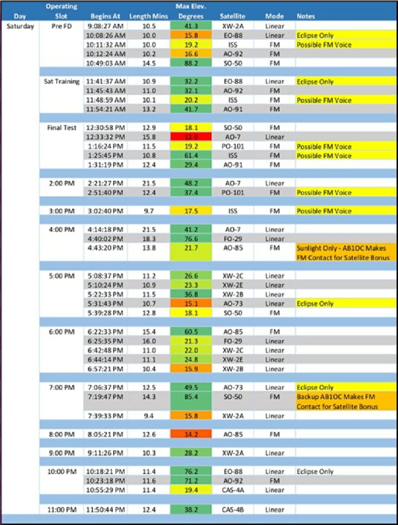
Field Day 2019 Satellite Passes – Saturday
We will have a lot of great satellite passes during Field Day this year! The table above shows a summary for Saturday. Sunday passes are also very good! You can see view the passes and associated details in our 2019 Field Day Satellite Pass Book.
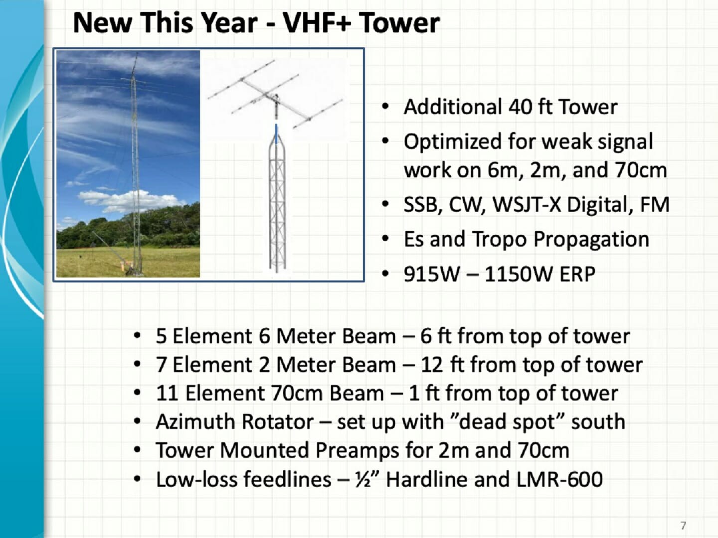
We are planning a serious VHF+ effort at Field Day 2019. We will be putting up a dedicated 40 ft tower with yagis, low-loss feedlines, and preamps for the 6m, 2m, and 70cm bands.
We will have several “Foxes” out during Field Day 2019. Fox Hunting (locating hidden transmitters using Radio Direction Finding) is a great way sharpen your RDF skills and have fun.
Training, Training, Training
Field Day Satellite Training
We will be offering training on all of these activities at the start of Field Day 2019. Training will begin at 11 am at the VHF+/Satellite Station Tent. We will cover Satellite Operating, VHF+ Operating, and Fox Hunting then.
Fox Hunting Training at Field Day
It might be worth coming to Field Day 2019 just for the training – Don’t Miss It!
We use cookies to ensure that we give you the best experience on our website. If you continue to use this site we will assume that you are happy with it.