At our most recent Tech Night meeting on Sept 12, at the end of the meeting, Fred (AB1OC) asked Brian (AB1ZO) to list a few of the upcoming tech night events.
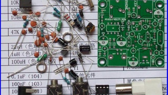
One such event would be to host a kit-building tech night. Plans are in the works to secure Pixie QRP kits (which run in cost from $3-$13) or some variant of this and assemble the kits during the allocated time. It’s expected that more experienced HAMs can mentor newbies in endeavors such as these.
Secondly, an informal poll was asked of members in attendance regarding the types of topics that would be of general interest. These included:
- Low-band antenna discussion: Due to the decreasing sunspot activity, “40m is becoming the new 20m”. What options to HAMs have to get on the lower bands, particularly if you are real-estate limited?
- Receiver vs Transmit antenna discussion — options for both
- High-frequency terrain analysis (HFTA) in order to better understand propagation effects of one’s signal
- Making sense of the influence of sunspot activity on amateur radio in general. Some energy, for example, could be dedicated to interpreting the sunspot GUI that appears on the website after login and understanding the science of the ionosphere.
- Working more with test-equipment kits and how to use them. This may include oscilloscopes, spectrum and network analyzers, frequency counters, signal generators, building CW paddles/keyers, and soldering kits.
- Using RTL-SDR dongles (or again some variant) and using them in small DIY projects that we could potentially complete in the allotted time.
I do want to say a few other things:
- Since our club is growing, and many new people are joining, I do want to stress that it is important that sometimes we “recycle” old Tech night topics in an effort to better educate our newer members. In this capacity, I would again hope that veteran members could help train younger ones. For example, I cannot solder to save my life. I would love some training during a surface-mounting tech night (since I couldn’t make the last one) and have someone experience show me the ropes.
- Many of you are working on interesting projects at home. No matter how small or large you think it is, I am 100% certain there are a group of people within the club who would like to hear what you have to say. So if you would like to present at Tech Night something you have been working on, please do not hesitate to email me at [email protected].
- I also want to solicit your feedback on this blog as well as my email for any other topics. The more suggestions we have the merrier! It’s important we adequately represent the interests of as many members of the group as we can.
In the coming weeks, I will start to construct a more concrete list of potential Tech Night topics, but help me — help you 🙂 Thanks for reading and see you on-the-air.
Best and 73,
Brian (AB1ZO)


")
