Category Archives: Education and Training

Education and Training information is for folks looking for help to earn or upgrade their license, learn about Amateur Radio, and get help with Ham Radio questions.

Broadband Matching for Antennas

This article discusses some work on designing a matching network to make antennas match well (low VSWR) across the entire ham band.  This will be a described in more detail at the September Tech Night.

Antennas have an impedance (or match) that varies with frequency.   Transmitters want to see a matched antenna with an impedance of 50 ohms.    The antenna has the best match at one frequency and the match gets worse as the operating frequency changes.

Some bands and antennas are more challenging to match than others.  Shortened or loaded antennas have a narrow range of match frequencies.  The 75/80 meter band has a wide bandwidth in term of percentage.

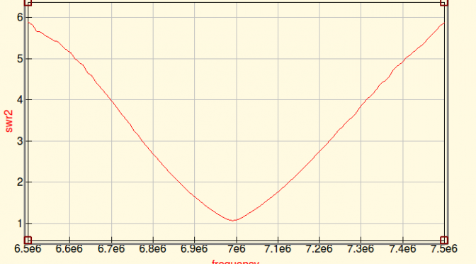
Here’s a plot of the SWR for my 40 Meter Dipole.  It’s a good match at 7.000 MHz and degrades to about 2:1 at 7.100 MHz.  Obviously, this is not optimized.

Broadband Matching - SWR for 40M Dipole
SWR for 40M Dipole

Modern radios have built in automatically adaptive matching networks make the radios work over a wider bandwidth, but networks are lossy and reduce transmitted power.

A manual antenna tuner has a lot lower loss than the built in tuner, but it requires manual adjustment.  In fact, the extra tuned circuits generally act to make the antenna have even less bandwidth.

The QUCS RF circuit simulation program has the ability to model SWR, bandwidth, matching networks based on data about antenna performance.  The antenna data can come from either an antenna modeling program such as 4NEC2 or EZNEC.  Or the data can come from a measurement made by a good antenna analyzer.

QUCS also has a built in optimizer.  It has the ability to try hundreds of circuit values and home in on an optimal design.

The optimizer setup needs a definition of “optimal”.  For the case of a broadband antenna, “The worst case SWR anywhere in the ham band shall be as low as possible”.  In the terms that QUCS understands, “minimize the maximum SWR over the frequency range 7.00 to 7.35 MHz.

Here is the result from running the optimizer on the data for my mistuned 40M dipole.  QUCS has designed a broadband matching network that can achieve less than 1.5:1 SWR over the whole band.

Broadband Matching

QUCS achieved this by varying the components of a filter network.  I drew a general filter network and let QUCS tune the component values.  This network is designed with coaxial stubs.

Broadband Matching

The model of the antenna is stored as a file in the X1 file component. Line7 is a 30-meter coax feedline.  The actual matching network consists of Line 1, 2, 3, 4.  Each line is 50 Ohm coax.  Line 1 and 3 are configured as open stubs.  The line lengths predicted by the model are…

  • Line 1: 7.75 meters
  • LIne 2: 4.47 meters
  • Line 3: 8.49 meters
  • Line 5: 8.03 meters

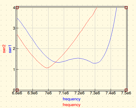
Here’s another example.  160-meter antennas are often implemented as shortened loaded verticals.  The loading makes the match very narrow-band.   The red curve in the plot below shows a top loaded 160 meter vertical.  It only covers a fraction of the band.Broadband Matching

The blue curve shows the result of an optimization run that selected the values for a 7 component matching network.  It achieves about 1.7:1 across the whole band.  This network uses capacitors and inductors because coax stubs would be very long on 160 meters.

Broadband Matching

The component values for this network…

  • C1: 3450 pF
  • L1: 3.954 uH
  • C2: 3978 pF
  • L2: 6.951 uH
  • C3: 6156 pF
  • L3: 2.831 uH
  • C4: 4778 pF

I have not built any of these networks to see how they work in practice.  The 160-meter network has some extreme values and it is probably very touchy to get right.  Building that network to handle Tx power will require vacuum variable capacitors in parallel with high quality stable fixed value capacitors.   But, the 160 network doesn’t really need 7 components.  Put in one less stage of L-C and the ripple across the passband goes up a bit.

Conclusions

QUCS is a great RF circuit simulator.  This shows that it can work with data from an antenna model or analyzer and can optimize matching networks to create a broadband antenna.

Jeff, WA1HCO

Hands-On Yagi Antenna Construction 2.0 for Teaching and Experimentation

The most important piece of equipment in ham radio is our antenna.  We are connected to the world with the magic of radio waves!  Each License Exam from Technician through Extra class has questions to test our knowledge on antenna design and building skills.  Home-brewed antennas are easy and relatively inexpensive projects.

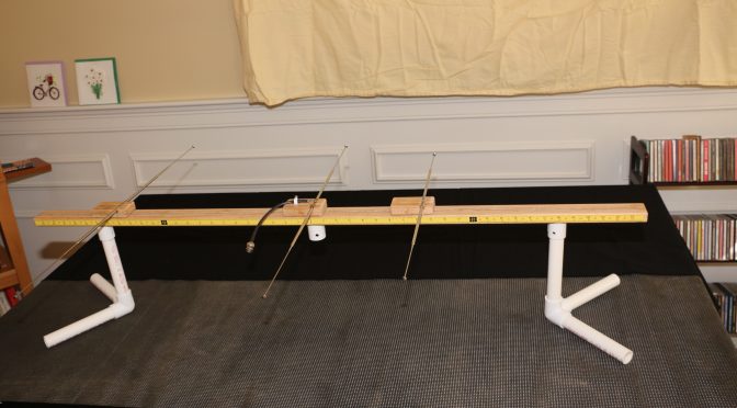
This article describes a 2m, 3-element Yagi antenna construction concept that the N1FD FCC license teaching team has used over the last year for class demonstrations.  The “Lego” style construction (v. 2.0) shown in the above picture is our new design that demonstrates the operating principles of the ubiquitous basic dipole antenna as well as a 2-meter, 3 element Yagi.  (Note, This project evolved from an earlier effort by Diana Eng at Makezine.com, which can be seen here.

In this Newsletter issue, we will describe the construction of the “Lego” stylized antenna and show how it can illustrate basic properties of a dipole antenna.  We will build a Yagi antenna with the addition of reflector and director arms in a future Newsletter article.

CONSTRUCTION of the LEGO STYLIZED ANTENNA.

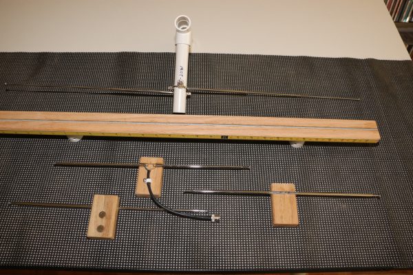
Yagi Antenna - Lego Antenna Parts and Receiver Antenna
Lego Antenna Parts and Receiver Antenna

The antenna demonstration unit consists of two assemblies. 

  1. A handheld receiver dipole set to a fixed frequency (e.g., 146.550 MHz). It is shown at the top of the photo above. It follows a “plumber’s delight” construction using pieces of PVC pipe for a short boom and handles.  The dipole arms are two telescoping (7-28 inch) FM radio replacement antennas, available on eBay or Radio Shack ($4-6 dollars).  The arms feed through the boom and are epoxied.  Bridging across the arms is a common 6-volt flashlight bulb.  The bulb lights up when the dipole receives a resonant rf signal.
  1. The “Lego stylized” Yagi antenna components are shown below the receiver unit. The boom (middle item) is made of red oak dimensioned at ¾  x  1 ½   x  48    The top surface is grooved to hold an epoxied  3/16  steel rod.  The bottom surface has drilled recesses to fit ¾ in PVC pipe for leg stands. The edge of the boom has two 24-inch adhesive tape rulers running from center to front and back of the boom.  The rulers read-out the spacing between the driven dipole element and the parasitic reflector and director arms. In the photo, the D.E. and parasitic elements are seen below the 48 in. boom.  The center element is the driven dipole and it is flanked by identical units that can be configured as either reflectors or directors.   Each unit consists of two telescoping FM radio antenna rods epoxied in a grooved piece of red oak ( ¾  x  1 ½  x  3 inches) serving as “riders” on the boom.  The telescope arms can be adjusted to “resonance” at any frequency in the 2-meter band. The bottom of all riders has 2 x ½ inch rare earth magnets.  These allow the three antenna elements to be fixed at any position on the 48 in. boom.

You can view a closer look at the assembled Yagi antenna configuration in this video (Click on Link)

DEMONSTRATIONS OF BASIC DIPOLE BEHAVIOR. 

1.  Antenna Resonance Determined by Dipole Length.

As we all know, the resonance length of a dipole is given by the equation:    L (in inches)  =  5616/ [ Frequency (in MHz)].  We can show this fact with aid of the “receiver” antenna, which is set for a frequency of 146.55 MHz  The light bulb of this antenna will light when it senses a signal of this value from our “Lego” antenna.

In the video below (Click on Link), we begin with a resonant D.E. length of 38.5 inches and see the receiver antenna light up.  Next, we manually shorten the D.E. and see the bulb light dramatically dim.  When the D.E. length is returned near the start value, the light bulb again brightens up.

  1. Effect of SWR on Signal Strength.

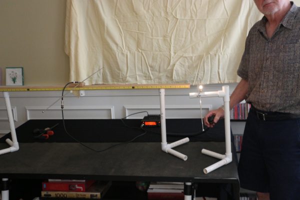
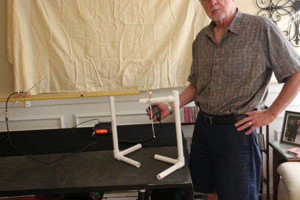
Most modern transceivers have a built-in auto-tuner that can match SWR up to 3:1.  We know this only makes the “radio happy”, still we key down without much thought on how our Tx signal degrades with a 3:1 match.  The pictures below use the transmitting “Lego” dipole and receiver dipole to show the received signals for an SWR of 1.1 and 3.0.  The SWR was changed by lengthening the D.E. elements by 2 inches while holding the Tx frequency at 146.55 MHz

Yagi Antenna - Receiver Signal-for Lego Dipole SWR 1.1
Receiver Signal-for Lego Dipole SWR 1.1
Yagi Antenna - Receiver Signal- for Lego Dipole SWR 3.0
Receiver Signal- for Lego Dipole SWR 3.0
3.  Polarization Effects between Tx and Rx Antennas.

A horizontal dipole shows “horizontal” polarization; meaning the electric field vector of the rf signal is parallel to the earth surface.  Similarly, a vertical dipole displays “vertical” polarization with the electric field perpendicular to the earth. We all learn this in a Technician class course.

When we use our 2m HT’s for short distance contacts, Tx and Rx antennas with opposite orientation create a huge signal loss.  The effect is shown dramatically in the video below.

CONCLUSION 

Our classroom constructible antenna for demonstrations in our Ham Radio license classes has evolved in design over the past year.  We believe it has been a useful resource,  helping students translate textbook theory to “Hands On” practice.  Perhaps, this review has kindled interest for our readers to think of their Next Antenna Project!

73 & Hope to hear you on the air,

Dave N1RF

Summertime Station and Antenna Projects At AB1OC/AB1QB

Summer is the time of year that many of us work on our antennas and improve our stations. Anita AB1QB and I did both of these things at our QTH this summer.

Antenna Projects - Removing Lower SteppIR Yagi From Tower
Removing Lower SteppIR Yagi From Tower

Our SteppIR DB36 Yagis were due for some maintenance so we took them off our tower. Special thanks to all the members of the Nashua Area Radio Club who helped us remove, recondition and reinstall our antennas! Matt Strelow, KC1XX of XX Towers and Andrew Toth provided equipment and know how to safely remove our two large SteppIR DB36 Yagis with help from the rest of us.

Antenna Projects - Lowering Antenna With Electric Winch
Lowering Antenna With Electric Winch

The SteppIR DB36 Yagis weigh almost 200 lbs each and Matt made good use of his electric winch to lower them.

Antenna Projects - Antenna Coming Down The Tram Line
Antenna Coming Down The Tram Line

The picture above shows the lower antenna coming off the tower. We used a Tram Line system to lower both antennas to the ground so that we could rebuild them.

Antenna Projects - SteppIR DB36 Antenna On The Ground
SteppIR DB36 Antenna On The Ground

The SteppIR DB36 Yagis are quite large. They have 36 ft booms and the driven elements are almost 50 ft from tip to tip! They completely fill up our back yard when they are both off of the tower.

SteppIR Rebuild

Antenna Projects - Element Pole Sun Damage
Element Pole Sun Damage

The rebuild process began with a careful inspection of both antennas. They were both in good overall condition with some sun damage to the paint on the fiberglass element poles.

Antenna Projects - Disassembled SteppIR DB36
Disassembled SteppIR DB36

We removed all the element tubes and sweeps from both antennas for rebuilding. The picture above shows the disassembled upper antenna.

Antenna Projects - Rebuilt Stepper Motors Installed
Rebuilt Stepper Motors Installed

All four Stepper motors on both antennas were replaced. These motors move metal tapes inside hollow element tubes to adjust the length of each antenna’s 4 movable elements. These adjustments are done automatically by controllers in our shack which receive frequency information from the radios which are connected to each antenna.

Antenna Projects - Reconditioned Element Sweep Poles
Reconditioned Element Sweep Poles

All of the element housing poles were cleaned, prepped and painted with a UV resistant clear coat to protect them from further sun damage. The poles cleaned up like new.

Antenna Projects - New Element Sweeps Ready For Installation
New Element Sweeps Ready For Installation

The assembly of all the new element sweep tubes (shown above) was done next. Each antenna has six sweeps.

Antenna Projects - Element Pole Preparation
Element Pole Preparation

The end of each element pole must be prepped with a tape system which ensures that the poles are seated properly, sealed to and firmly attached to the sweeps. This process and the associated assembly and tightening of the element couplers was the most time-consuming step in the rebuilding process as it had to be repeated a total of 24 times.

Antenna Projects - Rebuilt Element Assembly
Rebuilt Element Assembly

Here’s a picture of one of the rebuilt element tube assemblies. The ropes support the element tubes and keep them aligned when the antenna is up in the air. These elements are attached to the antenna motors with couplers and clamps.

Antenna Projects - SteppIR DB36 Yagi Rebuild Complete
SteppIR DB36 Yagi Rebuild Complete

The picture above shows the lower antenna with all the element tubes reattached. There is quite a bit of additional prep work associated with adjusting all the supports and taping all the exposed areas of the antennas which are susceptible to sun damage. Also, all the electrical wiring on the antenna must be checked to ensure good electrical connections and good overall condition of the wiring.

SteppIR Ground Testing


Antenna Projects - Ground Test Setup
Ground Test Setup

The final step in rebuilding the antennas is to test their operation on the ground. This ground test is done to ensure that all the motors are working correctly and that the element tapes move smoothly inside the rebuilt element tubes.

Antenna Projects - Ground Test Results
Ground Test Results

Another important part of the antenna Ground Test is to confirm that the antennas have a consistent resonant frequency and SWR on all bands. The resonant frequencies and SWR levels are far from those that would be measured when the antennas are on the tower at operating height. The idea here is to confirm that a resonance exists and that its frequency and SWR readings are repeatable as the antenna is adjusted to different bands.

SteppIR Installation and Final Testing


Tramming Antennas Onto A 100 Ft Tower

With both antennas rebuilt, its was time for Matt and Andrew to return and, with help from folks from our club, reinstall the rebuilt antennas on our tower. The video above shows this process. It is quite something to see! The installation took about 3 1/2 hours.

Antenna Projects - Updated SteppIR Controllers
Updated SteppIR Controllers

The last step in the SteppIR DB36 rebuild process was to install the latest firmware in the associated SDA100 Antenna Controllers. There were some integration issues between the updated SteppIR Firmware and our microHAM system but we are getting those worked out with help from the folks at both SteppIR and microHAM.

Transceiver Upgrade


Icom IC-7851 With Display Monitor

I recently had a major birthday milestone and Anita surprised me with a new radio – an Icom IC-7851. This radio is an upgrade/replacement for our Icom IC-7800. While the two radios are quite similar in their operation and interfaces, I did not want to install the IC-7851 until the SteppIR antennas were reinstalled and all of their upgrades were working properly with our current radios. With the antennas done, it was the time to install the new radio!

Icom C-7851 Transceiver

The Icom IC-7851 has several important performance upgrades. The most impactful one is a new low phase noise oscillator which significantly improves RMDR performance compared to the IC-7800. The IC-7851 is in the top-tier of Transceivers in Sherwood Engineering’s tests. The receivers in the IC-7851 are very quiet, have excellent Dynamic Range and perform great in when close-in interference is present.

Icom IC-7851 Display Monitor

The Icom IC-7851 has a higher resolution and faster display. It also supports higher resolution external monitors so we installed an upgraded display monitor along with the new radio. The IC-7851 has a number of new networking features and supports stand-alone remote operation over a LAN and the Internet. We are planning to use these capabilities to add a second remote operating gateway to our station. More on this in a future article.

The combination of the rebuilt antennas and the new IC-7851 Transceiver has our station performing better than ever. The antennas are working as well or better than when they were new and the IC-7851 has significantly better receive performance compared to its predecessor and is a pleasure to use.

We will be hosting the ARRL Rookie Roundup RTTY contest for our club members who have received their first license in the last 3 years next weekend and we’re going to use the new radio and rebuilt antennas for the contest.

This project was completed in a little over two weeks and was a lot of work. I could not have done the project without the help of the many folks in our club. Again, a big Thank You to all the folks in our club who helped me with this project! I hope that many of you will be able to find some time to operate from our upgraded station.

73,

Fred, AB1OC

Radio Amateurs Developing Skills Worldwide