Education and Training information is for folks looking for help to earn or upgrade their license, learn about Amateur Radio, and get help with Ham Radio questions.
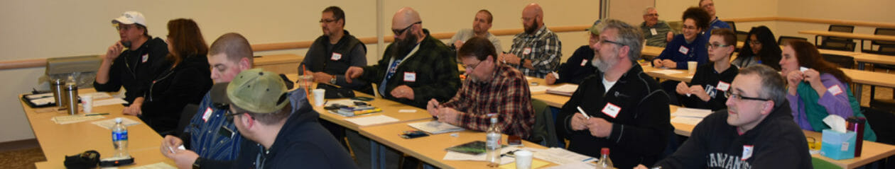
Our Fall Technician and General License classes held on September 24-25 and October 22-23 was a great success! We had a total of 10 new hams from our Technician class – 8 received their Technician License and 2 received their General Class License.
7 people received upgrades during our General class – 6 Generals and 1 Extra.
Congratulations to the following club members who received a license or upgrade through our classes!
Abby Finchum, KC1FFX, General
Connor Finchum, KC1GGX, General
Joe Kagenski, KC1GKP, Extra
Jill Gordon, KC1GKL, Technician
Carol Gardner, KC1GKO, General
Ben Scott, KC1GKN, General
Abby and Connor pass their General Exam
Thanks to the instructors and VEs who helped out in the License Class and VE Session!!
The Fall Extra Class will be held on December 2-4 at Dartmouth Hitchcock Nashua. There are still slots available in the class. If you are interested in the class, contact Anita, AB1QB at [email protected]
In Part 1 of this article series, I presented the “Lego” 2 m 3-element Yagi antenna design that the N1FD ham license teaching team has used over the past year for class demonstrations. The design allows easy assembly of the basic dipole antenna as well as a 3 element Yagi. The configuration of individual elements and spacing between elements can be quickly changed to demonstrate basic physics and behavior of these popular antennas.
The first article described antenna construction details and showed how to demonstrate the criterion for resonance as well as the polarization property of the radio wave. In Part 2 of the series, I will continue a focus on the dipole, specifically the spatial current – voltage profiles on the driven element and the radiation pattern of the antenna. We will use this information in Part 3 of the series next month to demonstrate how a 3-element Yagi works and why it is so popular.
THE CURRENT & VOLTAGE PROFILES ON A HALF WAVELENGTH DIPOLE
Figures 1a and b – Current Profile on a Half Wave Dipole Antenna
Note from Fig. 1b that the current profile of a dipole has a maximum current level at the center feedpoint and decreases to zero current at the end of each element arm. Contrasting, the voltage profile has a zero value at the feed point and increases to a maximum level at the ends of the element arms.
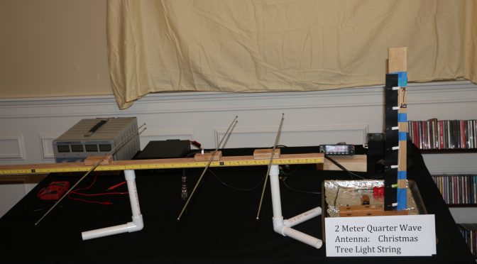
The 1/4 wave vertical antenna seen in Figure 2 can be used to visualize the current profile along the arms of a 1/2 wave dipole. The 1/4 wave antenna is made from a short length of a Christmas tree (incandescent) light string. The string length can be estimated from the standard equation: Length (ft) = 234/Frequency in MHz. Generally, several inches needs to be trimmed off because the lamps add “electrical length”. The shown antenna has the same resonance frequency as the Lego Style dipole we will use later (i.e., 146.550 MHz). The top end of the antenna is marked by the blue tape immediately above the 7th lamp.
Figure 3 – Transmitting mode. Note pattern of lit and unlit lamps.
The energized antenna with 15 watts RF signal is seen in Figure 3. Compare the pattern of lit and unlit lamps with the current profile sketch shown in Fig. 2b. The three lamps, counting from the picture bottom are brightly lit from an RF current. Lamps 4 and 5 show progressed less light indicating a lower RF current. Lamp number 6 is barely lit and number 7 is dark indicating together very little to no RF current at the element top end. The light pattern is a clear mimic of the diagram in Figure 1b.
Demonstration of the Voltage and RF Radiation Profile on a Half Wave Dipole Antenna
The voltage profile on a center fed 1/2 wavelength dipole is seen in Figure 1b. As mentioned above, the voltage is zero at the dipole center and increases in monotonic fashion to a maximum value at the antenna ends.
Figure 4 – Illustration of Dipole RF Radiation Pattern
The familiar RF radiation pattern of a dipole is shown in Figure 4 (taken from the cited source for Figure 1).
We are all well-schooled on the pattern, so I will just list the three key facts. First, the RF radiation is broadside to the antenna axis. Second, the RF field intensity is equal on the left and right sides of the dipole axis (i.e., there is no discerned “front to back” sidedness. Third, there is (theoretically) no RF radiation off the ends of the dipole wire.
The dipole voltage profile and the RF radiation pattern can be demonstrated using the basic dipole element of our “Lego Style” antenna and two simple tools. The voltage profile, or more correctly, the electric field strength around the dipole is sensed by a small fluorescent light tube. The actual RF radiation from the energized dipole is sensed by the flashlight lamp-bridged receiver antenna introduced last month in Part 1 of this series.
Direct RF Radiation Visual Detection
The video below (double-click in the picture box) demonstrates the use of the lamp-bridged receiver antenna to detect radiated RF power.
The video shows the flashlight bulb bridging the handheld receiver antenna lights up when it detects an RF signal that matches its resonance point at 146.550 MHz The light bulb is dark with no transmitted RF power from the Lego dipole. Keying the radio energizes the Lego dipole and the receiver lights up about equally on the right and left sides of the Lego antenna. This reflects the figure 8 pattern of RF power illustrated in Figure 4.
Voltage Profile witnessed by the Electric Field Strength.
The next video (double-click in the picture box) employs the fluorescent light bulb to map the voltage profile along a dipole arm by sensing its electric field strength. An RF electric field causes a series of chemical reactions within the light bulb that produces a bright fluorescent light.
The light bulb is dark when the Lego dipole is not transmitting an RF signal. Keying the radio generates an RF signal and the associated electric field around the dipole element causes the bulb to light up. Note, the bulb is very bright adjacent with the side end of the dipole arm and extinguishes as it is moved to the dipole centered feedpoint. Also, the light is dimmed at the antenna tip in-line with the dipole axis.
The voltage profile map seen in the fluorescent light bulb video augments the RF signal map seen in the lamp-bridged receiver antenna video. Also, it extends our demonstration to the expected observation that there is (theoretically) no RF radiation off the end tips of dipole elements.
CONCLUSION
In this second installment of our Lego-Style Antenna series, we have shown how this construct together with two simple tools can be used in the classroom to demonstrate basic properties of the ubiquitous dipole antenna; Namely, criterion of resonance, generation of RF radiated waves, the polarization of the RF field (horizontal or vertical) and the general propagation geometry of these waves relative to the antenna orientation.
In Part 3 and last installment of this series we will continue to use the Lego-Style Antenna in its’ Yagi configuration together with the two accessory tools to show how properly designed and placed reflector and director elements on the Yagi antenna can shape and control the dipole rf signal to increase gain via spatial directivity and improve signal selectivity by the “front-to-back” ratio that it creates.
At our most recent Tech Night meeting on Sept 12, at the end of the meeting, Fred (AB1OC) asked Brian (AB1ZO) to list a few of the upcoming tech night events.
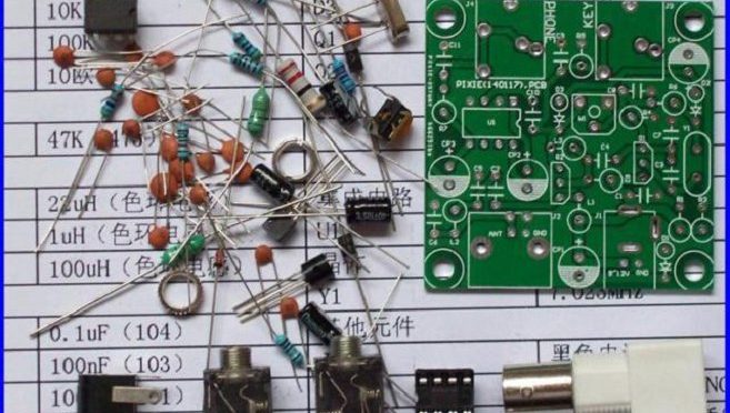
One such event would be to host a kit-building tech night. Plans are in the works to secure Pixie QRP kits (which run in cost from $3-$13) or some variant of this and assemble the kits during the allocated time. It’s expected that more experienced HAMs can mentor newbies in endeavors such as these.
Secondly, an informal poll was asked of members in attendance regarding the types of topics that would be of general interest. These included:
Low-band antenna discussion: Due to the decreasing sunspot activity, “40m is becoming the new 20m”. What options to HAMs have to get on the lower bands, particularly if you are real-estate limited?
Receiver vs Transmit antenna discussion — options for both
High-frequency terrain analysis (HFTA) in order to better understand propagation effects of one’s signal
Making sense of the influence of sunspot activity on amateur radio in general. Some energy, for example, could be dedicated to interpreting the sunspot GUI that appears on the website after login and understanding the science of the ionosphere.
Working more with test-equipment kits and how to use them. This may include oscilloscopes, spectrum and network analyzers, frequency counters, signal generators, building CW paddles/keyers, and soldering kits.
Using RTL-SDR dongles (or again some variant) and using them in small DIY projects that we could potentially complete in the allotted time.
I do want to say a few other things:
Since our club is growing, and many new people are joining, I do want to stress that it is important that sometimes we “recycle” old Tech night topics in an effort to better educate our newer members. In this capacity, I would again hope that veteran members could help train younger ones. For example, I cannot solder to save my life. I would love some training during a surface-mounting tech night (since I couldn’t make the last one) and have someone experience show me the ropes.
Many of you are working on interesting projects at home. No matter how small or large you think it is, I am 100% certain there are a group of people within the club who would like to hear what you have to say. So if you would like to present at Tech Night something you have been working on, please do not hesitate to email me at [email protected].
I also want to solicit your feedback on this blog as well as my email for any other topics. The more suggestions we have the merrier! It’s important we adequately represent the interests of as many members of the group as we can.
In the coming weeks, I will start to construct a more concrete list of potential Tech Night topics, but help me — help you 🙂 Thanks for reading and see you on-the-air.
We use cookies to ensure that we give you the best experience on our website. If you continue to use this site we will assume that you are happy with it.