Education and Training information is for folks looking for help to earn or upgrade their license, learn about Amateur Radio, and get help with Ham Radio questions.
I once again had the pleasure to help a group of young people make contact with an Astronaut on the International Space Station this past week. Scouts from the Matinecock District in Long Island, NY, made a contact wi…
It was a lot of fun helping the Scouts of Sussex County, NY, talk to an astronaut on the International Space Station (ISS) this weekend. You can read all about the contact and see a video via the link above.
On May 11, 2022, members of the Nashua Area Radio Society 2022 Field Day Tower and Antenna Teams met at BOB for a hands-on training exercise led by Fred AB1OC. BOB stands for Big Orange Box, the trailer that we use to store our gear. After obtaining approval from the facility where BOB is parked, we erected a 40-foot tower with a beam antenna and other peripherals to build our team’s skills prior to Field Day in June. We met there at 8:00 AM and began our day by removing all of the storage bins from the floor of the trailer to give us access to the tower sections, antennas, and other gear we need for the exercise.
Preparation
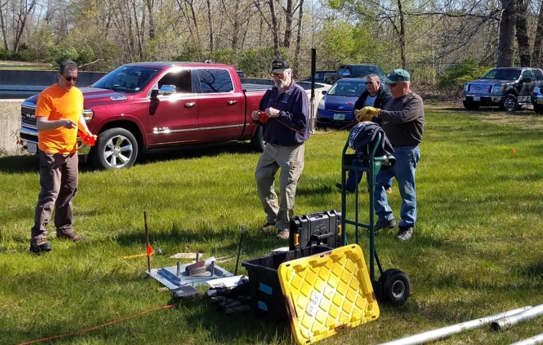
Plan Base Location
The next step was to identify a level spot for us to place the tilt base for the antenna that would also allow us to have room for the boom, derrick, winch, and guy lines. Our location for the training was compact but had enough room. In June our Field Day location has much more room, so this will not be an issue.
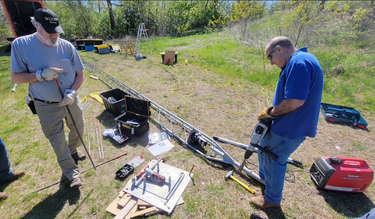
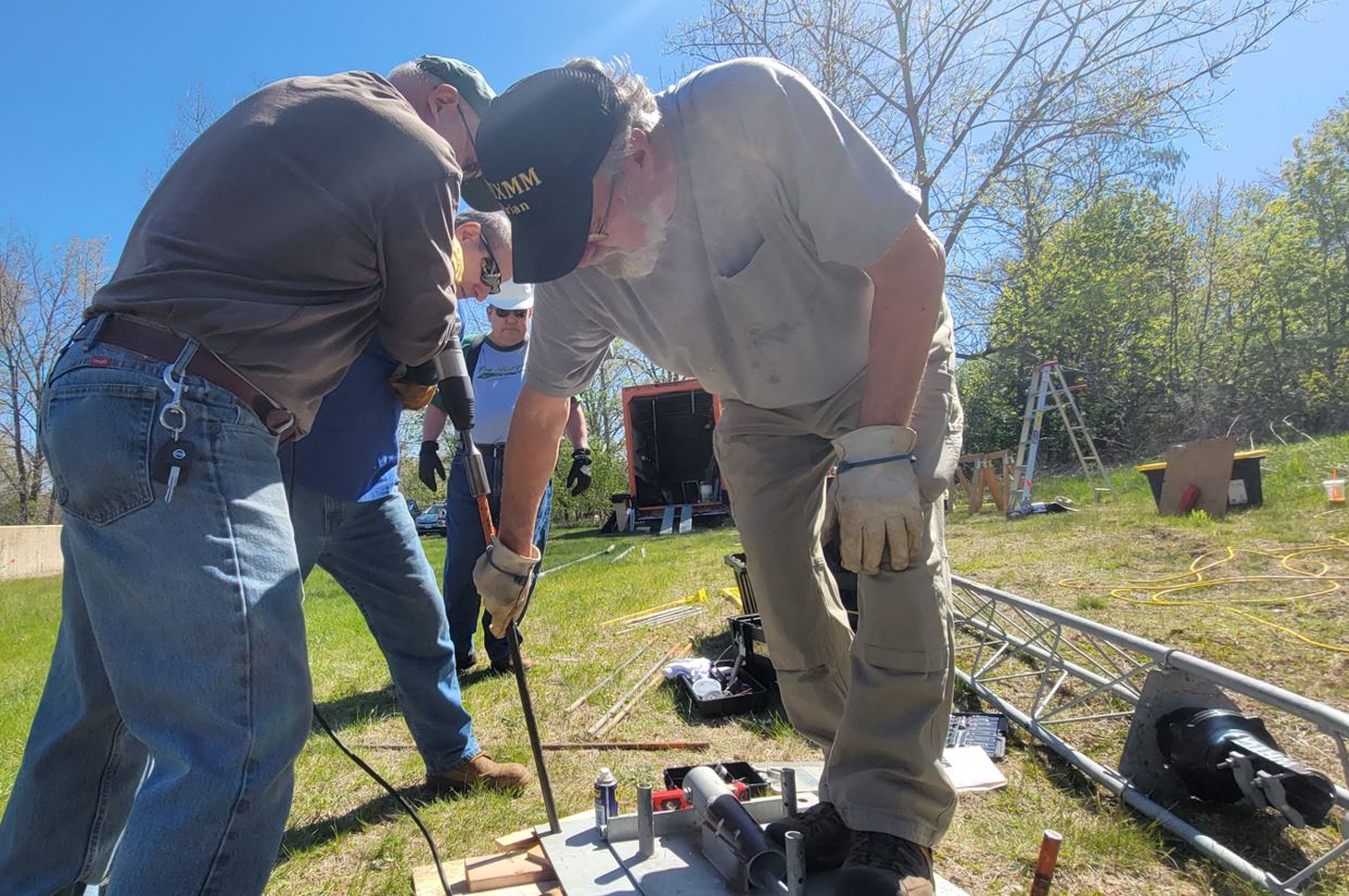
Prepare Base
Using the impact hammer to drive in 4-foot stakes to secure the base plate to the ground. The base is subjected to a lot of stress and strain during the lift so must be level and tightly secured to the ground.
Drive Rods with Impact HammerReady to Rig Falling Derrick
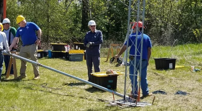
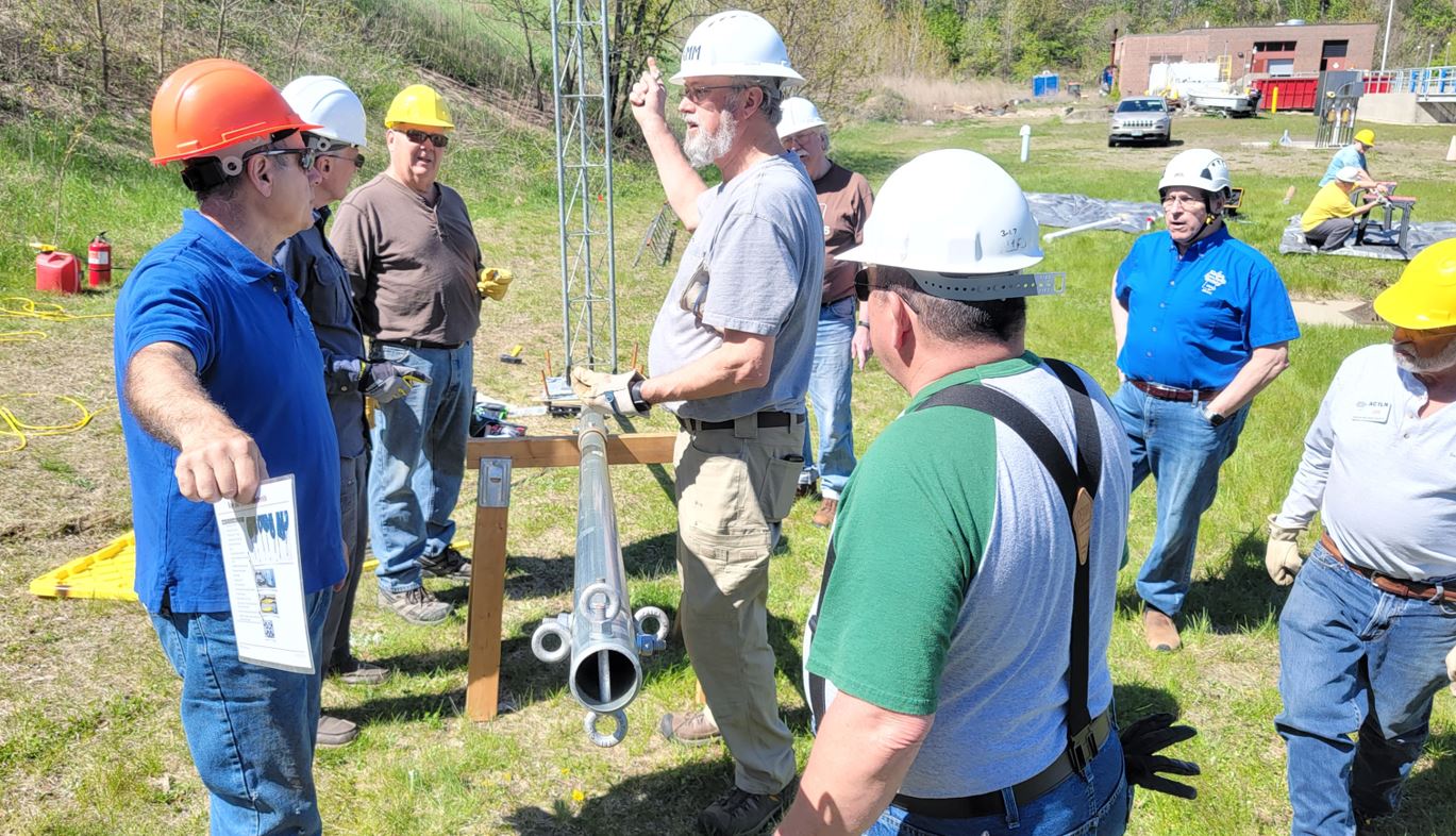
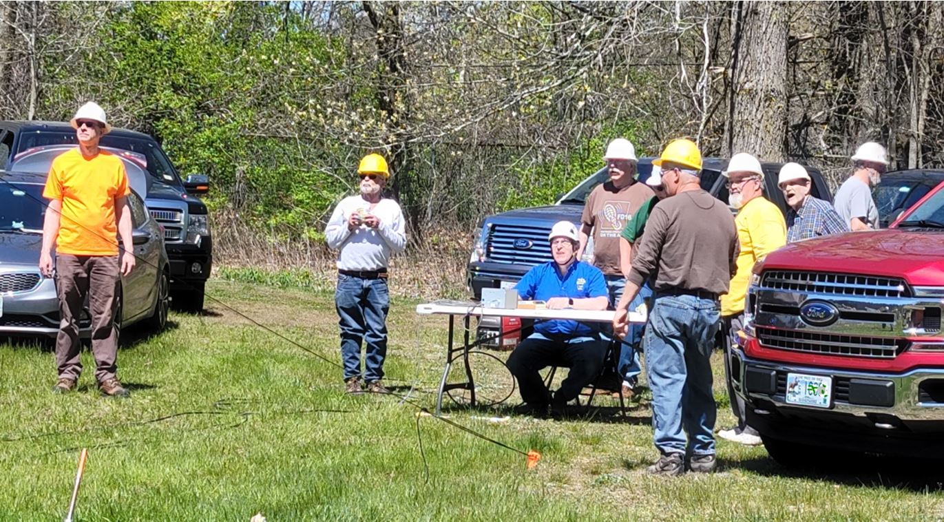
The team gathers around for a briefing on the next steps after assembling and installing the falling derrick pole and also setting the first section of the tower into the base.
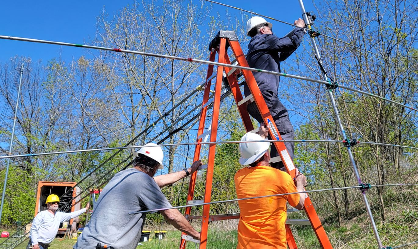
Prepare to add tower sections
Once the falling derrick is fully configured with all guys and cables attached, we raise it to lower the first tower section so we can add the remaining sections to it while on the ground. Here as in other stages of the construction Fred is guiding us and monitoring our progress.
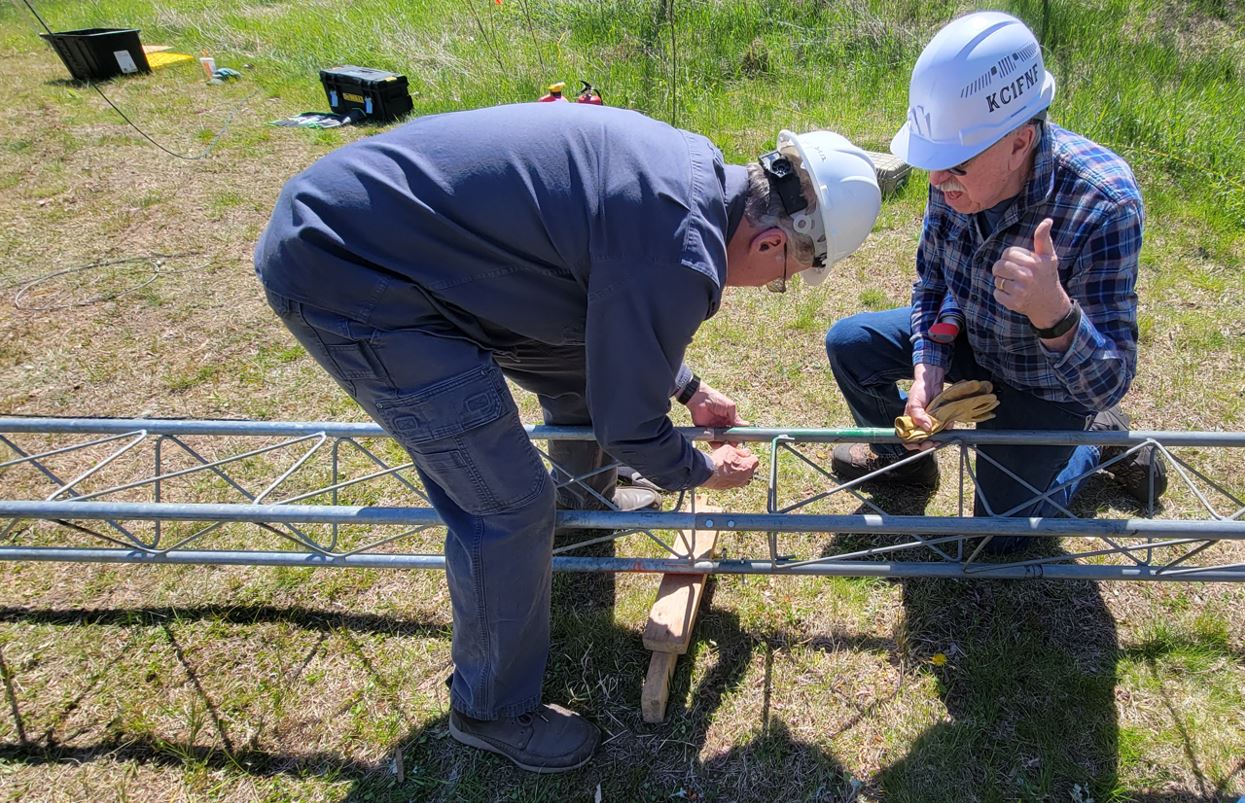
Bolt Tower Sections
Tower team members bolt together the tower sections securely.
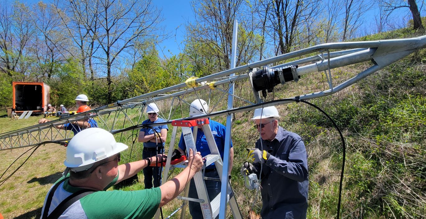
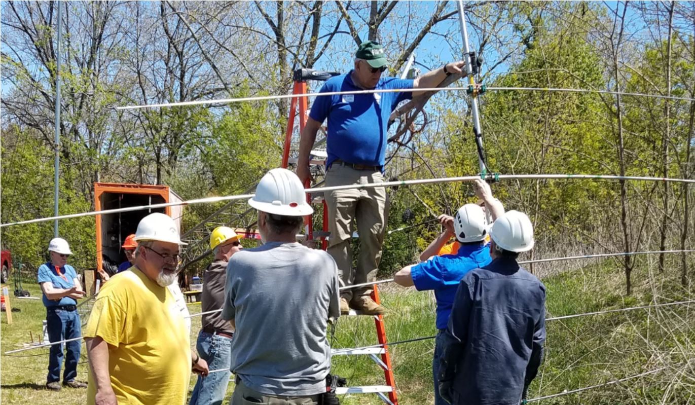
Add cables and other peripherals
Prior to raising the tower, all of the peripherals need to be installed. Here is the cross beam that will hold 40-meter and 80-meter dipoles. The coax for the beam antenna and control cable for the rotator are secured to the tower as well.
Move Assembled Antenna to Tower
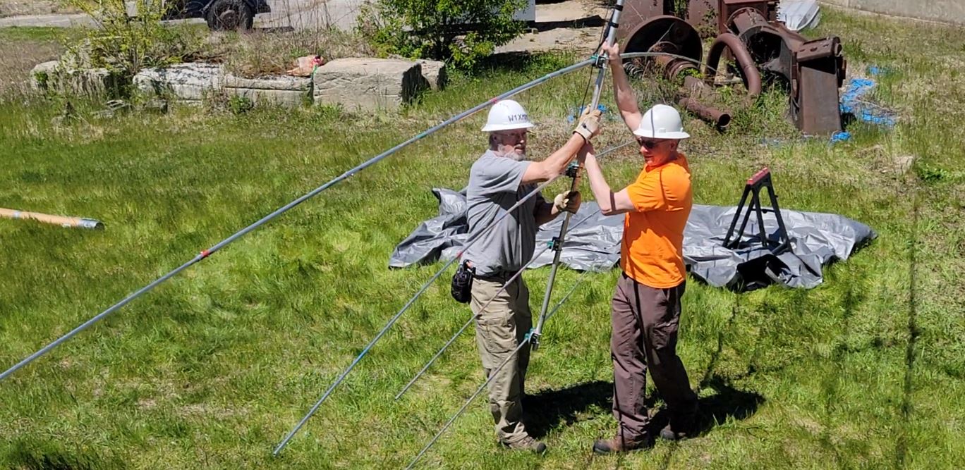
We orient the assembled beam antenna front down so when we raise the tower it is pointing in the proper direction. This is determined by how the tower is oriented and how the rotator is set prior to raising the tower.
Attach Antenna to Mast
We slip the U-bolts on the antenna onto the mast and tighten them. Next, we connect the coax to the antenna with a long enough loop to allow for it to rotate more than 360 degrees.
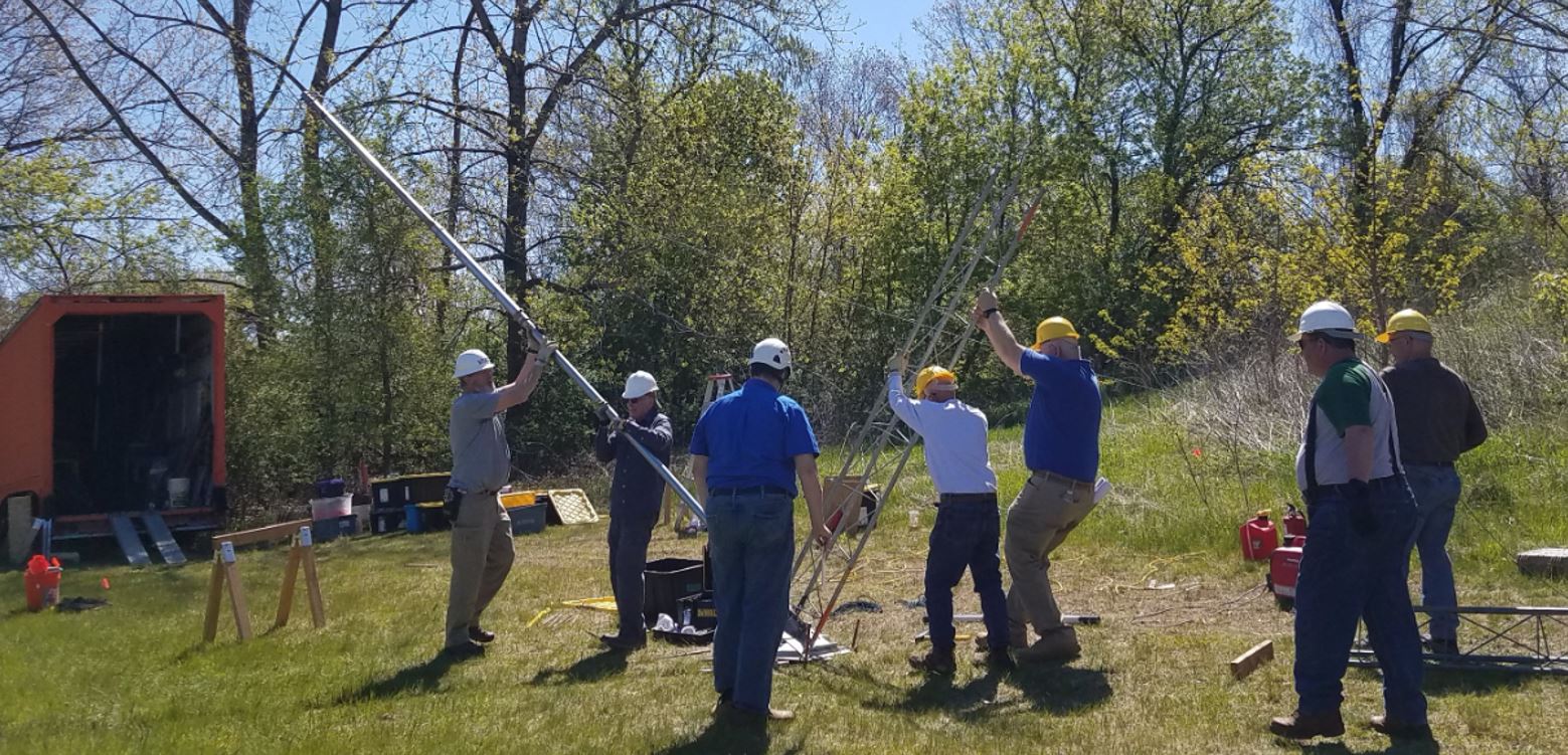
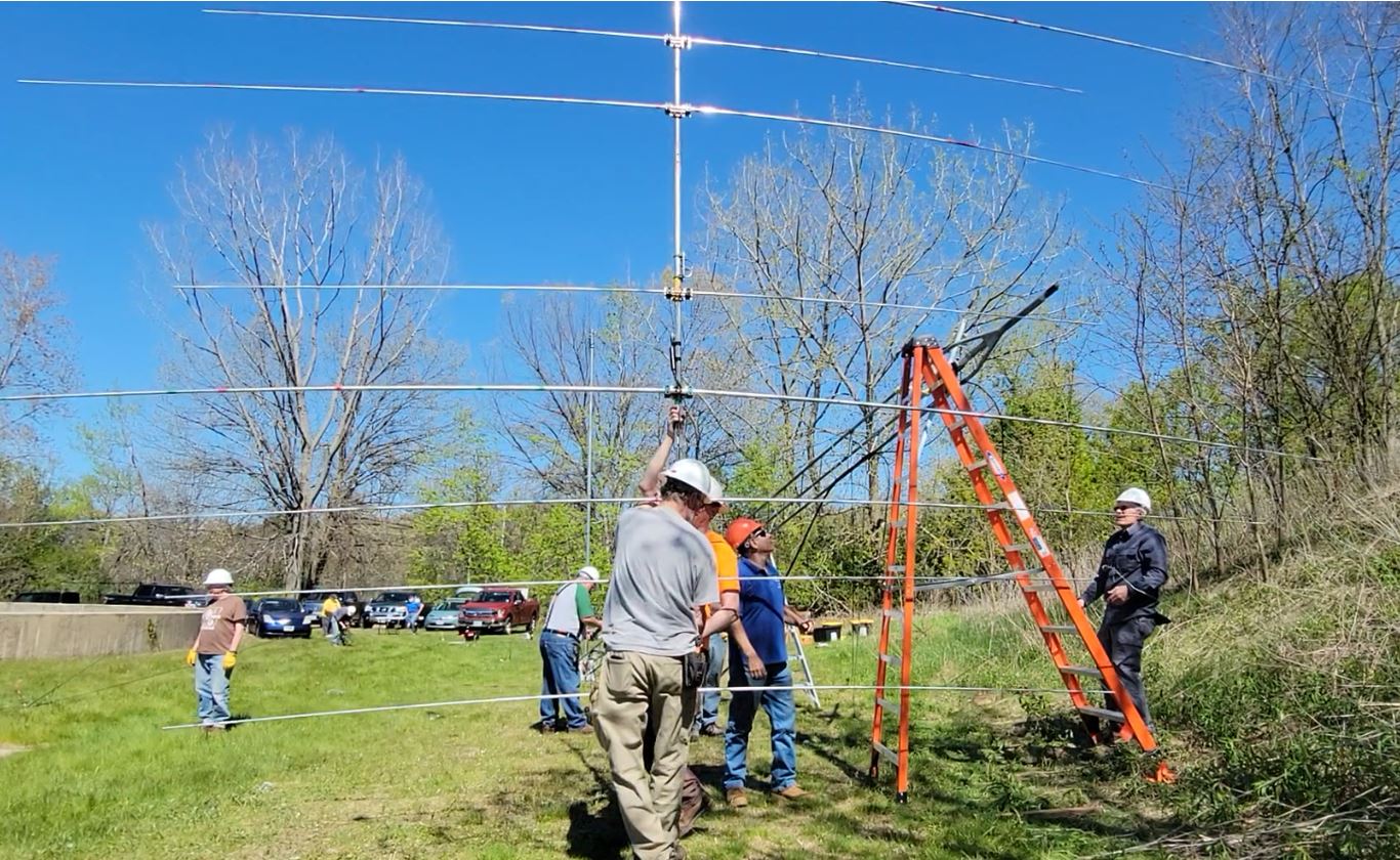
Raise the Tower
View the Hyperlapse above
Watching Rotator Test
The crew watches as we test the rotator and confirm that there is enough loop to rotate without any interference or binding. The test was successful and afterward, Fred AB1OC made a few DX calls to Europe QRP with an IC-705 radio. The beam worked great!
Disassembly and Storage
Prepare to Remove Antenna from Tower Mast
Around 2:30, after only 15 minutes of operating, we needed to reverse the process and disassemble the tower and antenna. Our target time for departing the facility was around 4:00 PM.
Remove Antenna from Tower
The Beam team removes the antenna and moves it for disassembly until Field Day. At the same time, the Tower team will break down the tower and peripherals.
Ready to Disassemble Antenna
We place a tarp under the antenna in case any small parts fall off. It is easier to find them from the tarp than from the tall grass. Working on it on the sawhorses makes it much easier to assemble or disassemble.
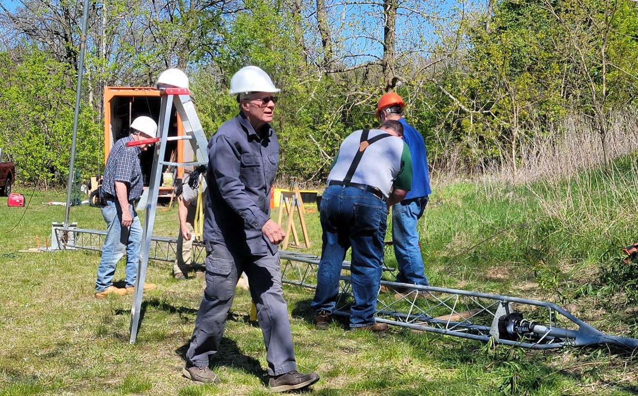
Breaking Down Tower Sections
The Tower Team breaks down the tower sections while carefully keeping track of everything so we can be sure we have what we need for Field Day at the end of June.
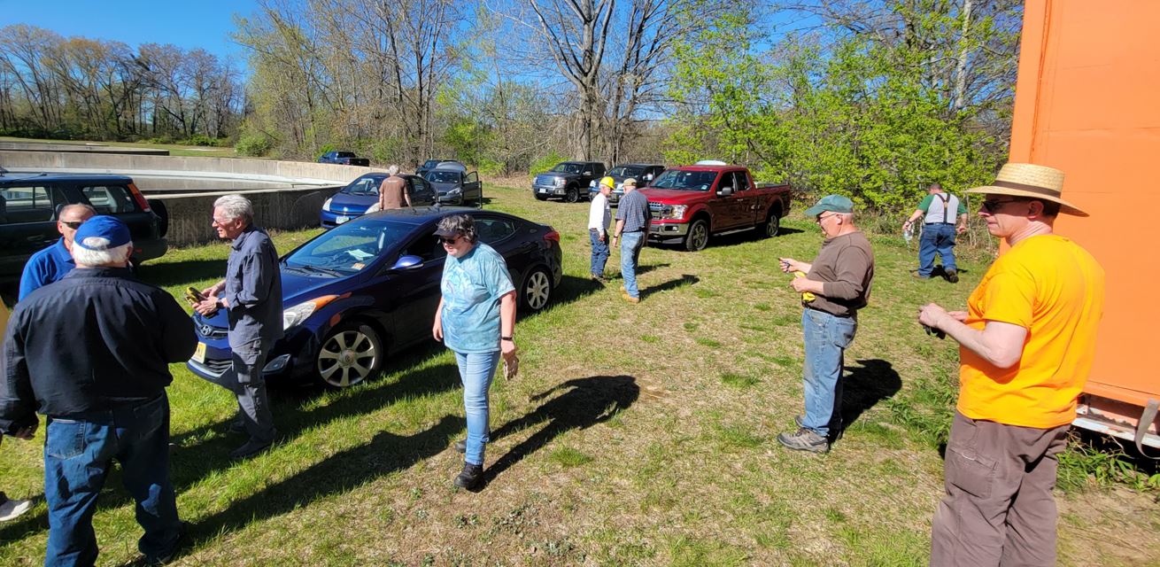
Gear Stowed and Ready to Leave After Successful Day
We are ready to leave after a successful day. Thanks to Fred AB1OC who guided us through the different activities. He helped us all to gain more information on how to perform this task safely and efficiently.
Field Day can be a complex project
Field Day provides clubs with a number of opportunities. The obvious are to have a chance for members to gather and operate together. Even though it is not a contest, per se, we do keep score. The event also provides a chance for members to participate in a complex group project. Some of us had experience with projects of similar complexity in our careers but others never did. Working together collaboratively on a project like this is a good basis for friendship and memories of the shared experience are long-lasting.
Building Skillsets in the Club
One of our goals as a club is to build a skill set within the club that persists as members move in and out of active participation in these activities. We have members this year who have years of past experience doing this and others for whom this is their first exposure to it. Members who were prime contributors a few years ago may no longer participate. After this Field Day, we will have a new core of experienced members who can handle these tasks and share their own experiences to mentor the new members who will follow them. We strive to build a culture that continues to promote the continued building of the required skills in the club to share with future members.
Are you a newly licensed Technician, or a General or Extra and have never been on the air or built a station? Are you a prospective ham but would like to learn more about Amateur Radio activities? Ham Bootcampis the program for you. We will be holding another online Ham Bootcamp on Saturday, May 14th, 2022.
Registration is open for the Nashua Area Radio Society’s Spring Ham Bootcamp. Ham Bootcamp will be held online using Zoom web conferencing. This will also let us reach out to new Hams across the country.
Jamey, AC1DC, elmers Randall, N1KRB as he makes an HF Contact
Our spring Ham Bootcamp will be held on Saturday, May 14thfrom 10:00 am to 6:00 pm Eastern Time. The morning session will focus on Technician level activities and the afternoon session will focus on HF activities for General and above licensees. New this year will be a breakout session where attendees will have a choice between 3 different sessions.
Here is the agenda:
Abby Speaks About Fox Hunting in Fall 2020 Ham Bootcamp
Repeaters and VHF/UHF Session Activities
Putting together a Station for Repeaters – How to pick an HT or Mobile Radio and an Antenna
Making Contacts and Joining a Repeater Net
Radio Programming Tutorial
Getting Started with Amateur Radio Satellites
Getting started with Fox Hunting
Jamey Explains HF Station Building
HF Session Activities
Putting together an HF Station for SSB, CW, and Digital
Picking and putting up an HF Antenna, Feedlines, and Grounds
Operating on the HF bands using SSB Voice
Getting started with WSJT-X and FT8 Digital
Breakout Session
The final session of the day will be a breakout session where attendees will choose to attend one of the following 3 sessions:
Learning CW
Finding DX, Logging Contacts, and QSL’ing – Getting them logged/confirmed
Portable Operating
Spring 2022 Ham Bootcamp will be Online on May 14th
Registration is now open for the May 14th session. You can get more information about Ham Bootcamp at https://www.n1fd.org/ham-bootcamp/.
Each attendee should register separately using this link. After registering, you will receive a link that will allow you to register for the Zoom meeting. Following the Zoom meeting registration, you will receive a personal Zoom link via email.
We use cookies to ensure that we give you the best experience on our website. If you continue to use this site we will assume that you are happy with it.