Articles and Information related to Digital Modes. Topics include PSK, RTTY, JT Modes, APRS, operating using Digital Modes, equipment, software, and more.
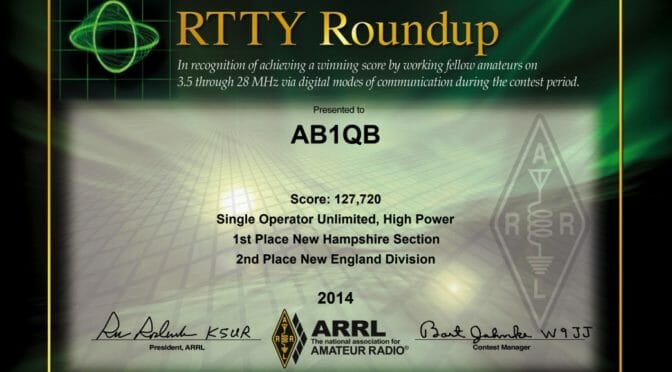
This is the first year that the FT8 mode will be part of the ARRL RTTY Roundup. The newest version of the WSJT-X software, version 2.0, has been enhanced to support the contest exchange. See Joe Taylor’s QST article for details on how it will work.
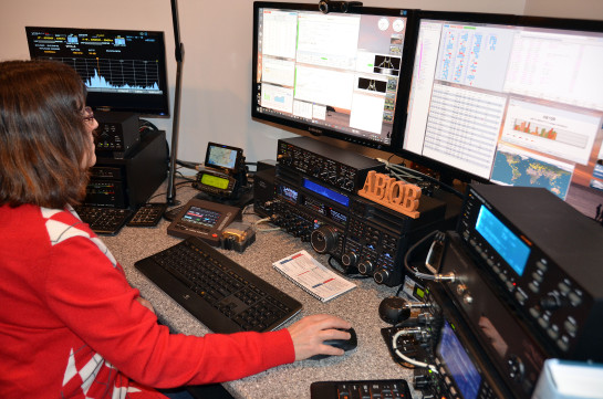
AB1QB operating in a RTTY Contest
Fred, AB1OC and Anita, AB1QB will be hosting a multi-op entry using the N1FD callsign from their QTH. The contest starts at 18:00 UTC (1:00 pm EST) on Saturday and ends at 23:59 UTC (7 pm EST) on Sunday. The first few hours of the contest overlap with ARRL Kids Day so the kids will have priority on our main station. We may be able to operate in the RTTY Roundup using FT8 and our SteppIR Vertical.
If you are interested in signing up for a time slot, please contact Anita, AB1QB at [email protected]. Let her know what time you can be available to operate and how many hours you would like to operate. Please respond no later than Thursday. She will put together an operating schedule and send it out on Friday.
We hope to see you this weekend in the contest or hear you on the air!
A number of people have had difficulty setting up their radios using the USB interface for WSJT-X and FT-8. It helps to have a basic understanding of the computer interface within the radio. The good news is Kenwood, Icom, Yaesu and even SignaLink share a similar architecture, often down to the same device part numbers and software drivers.
Once the USB cable is connected to the radio the first device in the data path is a USB Hub. Just like a Hub, you might use on your desk its function is to provide multiple USB ports with only one cable from the PC or Laptop. It does not require configuration or drivers and is transparent to the user.
There are two devices connected to the Hub inside the radio. They are a USB UART Bridge and an audio CODEC. If there wasn’t an internal Hub each of these devices would have a separate USB cable to the PC. This is important as it shows how separate and independent they are when setup, access, and drivers are considered.
Kenwood, Icom, and Yaesu use a USB UART Bridge from the SiLabs CP210X family. (SignaLink does not have a serial CAT interface). All three plus SignaLink use a USB/CODEC from the Ti PCM290XB family.
We will review the functions and setup of the USB UART Bridge first.
USB UART Bridge
A “Bridge” may sound complicated but all this device does is accept bi-directional USB and produces bi-directional serial data. It is a bridge between USB and serial data.
You may have used an adapter with a USB connector on one side and a DB-9 9 pin serial connector on the other side. It is likely it used the Silabs CP2101 or a similar device made by FTDI. This interface is often referred to as a Virtual Com Port (VCP) which replaced “real” DB-9 Com ports found on computers into the 1990s. It is called virtual because much of the serial COM port functionality is achieved with software.
The radios that can be computer controlled have a CAT interface (computer-aided transceiver). A related term is CI-V (Communication Interface v5) which is an Icom standard that defines the messages the radio will respond to. The messages are in text (ASCII) format, for example, to transmit you would write TX; to the radio. With a serial interface or VCP, you can send ASCII text messages to your radio using Hyperterminal or an application called PuTTY and it will respond.
Older radios used a CAT interface that required a serial COM Port on the PC. Most of the current radios can still accept serial data through an ACC (accessory port), and a few still have a DB-9 9 pin connector for serial data. Newer radios also have a USB interface and use the USB UART Bridge to receive the serial CAT/CI-V messages from the PC. A radio menu setting is used to select data over an ACC or the USB for radio control.
Audio is not passed using the USB UART Bridge CAT/CI-V interface, it is strictly used for radio commands.
WSJT-X uses a small set of messages over the CAT interface to control the radio. These include band changing, VFO frequency, PTT and a few others.
The USB UART Bridge requires a VCP driver that must be installed by you before connecting the radio to the PC. If you connect the USB cable before installing the driver Windows may locate and install a driver, this works less often than auto-correct in spell check. Once the wrong driver is installed it can be very difficult to uninstall. The correct driver can be downloaded from the radio manufacture’s website.
Once the driver is properly installed and the radio connected the driver can be found in the Windows Device Manager as shown in Figure 1. Note the COM Port number, you will need it to configure WSJT-X. Your COM port number will probably be different.
Figure 1 USB UART Bridge Driver
By right clicking on the driver and selecting properties and then the Ports tab you can set the Baud rate, Parity, Stop Bits, and flow control as seen in Figure 2.
Figure 2 USB UART Bridge Settings must be the same in Device Manager and WSJT-X
Typical settings are as follows:
Baud Rate: 9,600 (Standard values from 9,600 to 115,200 can be used)
Parity: none
Stop Bits: 1 (7300 or 590S/SG 1 or 2 can be used, older rigs and SignaLink with a CP2101 must use 1)
Flow control: Hardware
The settings you select in Device Manager Properties must be used in the WSJT-X setup.
Once these settings are set for the COM port and in the WSJT-X app consider them set, and leave them. If you have completed these steps and do not have CAT/CI-V control of the radio it is due to incorrect radio settings, a bad/cheap cable, you are connected through an unpowered Hub, or are using the front panel USB port of a PC. (Front panel USBs are hit and miss).
Yaesu radios have an additional USB UART Bridge accessible through the hub. You will see an Enhanced port for CAT and a Standard port for PTT in Device Manager. Each has a unique COM port number. WSJT-X has a spot for a second COM address in Settings/Radio for “PTT Method”. The Standard port COM address and RTS is entered for PTT Method. I have used these setting for an FT-991 and FTDX-3000.
CAT is selected for PTT for Icom and Kenwood radios, a second COM address is not used.
USB (AUDIO CODEC)
The second device on the Hub’s output is a CODEC. The CODEC decodes the digitized audio on the USB to analog using an ADC, and using a DAC the analog audio from the radio is digitally coded to be sent to the PC over the USB. Taken together with CODEC COdes and DECodes audio signals from a digital format.
There are no COM port addresses, baud rates, stop bits, etc for you to set since it is not a VCP, it is a standard USB interface.
A PCM290x CODEC is used in the IC-7300, TS-590S/SG, FT-991, SignaLink, and others. The driver is included with Windows XP through 10 so there is nothing for the user to install. Once the CODEC has a USB connection and power it will automatically be installed and set up. The CODEC will appear in Windows Device Manager under “Sounds, Video, Game Controller” when power is applied to the radio. It can be seen in Figure 3 as “USB Audio CODEC”. If there is more than one and you are not sure which one is the radio’s disconnect the USB cable and see which one disappears and then reappears when reconnected.
Figure 3 “USB Audio CODEC” in Device Manager and WSJT-X
If the driver has been used with multiple radios it may appear as “3-USB Audio CODEC” or similar which is not a problem provided the same exact label as seen in Device Manager appears in WSJT-X and the Windows Sound settings.
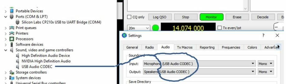
The audio CODEC was identified as “USB Audio CODEC” in the device manager, WSJT-X, and was the selected Input and Output device in the Windows Sound Setting as seen in Figure 4.
Note: The label “microphone” has been replaced with “Line” for PCM290XC rev C CODECs used in the TS-890, other recently released radios, and when a CODEC is replaced due to failure.
Figure 4 Windows Sound Manager
Summary
Knowing there is a Hub and two independent USB devices in the radio should help when setting up a radio for WSJT-X. The first device is a USB to Serial converter supporting CAT/CI-V, the second device is a USB to Audio CODEC supporting audio input and output.
You will not resolve audio issues by changing the USB UART Bridge settings for baud rate or the number of stop bits. Similarly changing the audio I/O devices is not going to solve a CAT/CI-V problem.
I was surprised to learn the driver we install is only a generic USB UART Bridge. I expected a large complex proprietary composite driver that handled the CAT/CI-V and the audio CODEC. The audio CODEC driver is a standard Windows product.
I have identified the various switches on the radio’s circuit boards and their related menu functions. An example is the switch and menu item that connects the audio I/O from the radio’s processor to the ACC port, Microphone, or the CODEC. I plan to do a separate article on this topic.
In the interim knowing, there are two independent devices should help demystify the menu settings a bit. Baud rate, USB for CI-V, Echo on, etc are for the CAT using the SiLabs USB UART Bridge. Audio I/O levels, Modulation source, and related options only apply to the USB CODEC.
This article may seem a bit bottoms up. It was written from the vantage point gained while troubleshooting and then replacing Hubs, bridges, CODECs and surrounding devices in numerous radios. USB is the most fragile interface on the radio when lightning is a factor….these are the parts at the end of the USB cable.
The FT8 digital mode that Joe, K1JT, and company rolled out a little over a year ago has become a game changer in ham radio. The mode is a modification of the JT9 & JT65 weak-signal modes that have been around for nearly ten years, an eternity in the digital world. These modes, while great for modest stations (read: apartment and condo dwellers; CC&R prisoners; and those with an iron-willed spouse who does not like antennas), suffered from a SLLOOOW exchange cycle. A rapid QSO with a signal report, acknowledgment and 73 might make it in four minutes. FT8 cuts the time to less than half that. The migration to FT8 has left the JT9 & JT65 band segments virtually deserted today.
The burgeoning success of FT8 has led to the development of a DXpedition mode that uses a “fox and the hound” model with the DX being the “fox” and the rest of the world being the “hounds”. The mode enables the DX station to transmit simultaneously in up to five slots at the low end of the FT8 band segment and work hounds operating in the rest of the segment, racking up several hundred QSOs/hour. Still another version is in beta testing that will be used for the RTTY Roundup contest in a couple months. Support for Field Day 2019 is just around the corner.
I’ve found FT8 a great way to keep chasing DX that I just cannot hear on CW let alone SSB. I’ve amassed 1300 QSOs to date and over 140 countries which says a lot with the disappearance of sunspots. All this time watching calls scroll by has given me a chance to observe operating habits good and bad. Good operating is being able to call a DX station off-frequency to increase the probability of being decoded. Bad operating practice is cranking up the power to spill over into another slot and even desense the station you are trying to decode.
Recently, I noticed a strange phenomenon from stations presumably running high power. Signals in FT8 usually have a received level from -2 to -22 dB that is adequate for decoding. Strong signals such as local stations or stations in the first skip zone with levels of 0 to +5 dB obviously are not hard to decode. However, I’ve seen some stations with a received signal level of +4 to +15 dB or more have a second decoded slot with a signal level of -13 dB or lower. Furthermore, this second decoded slot is always 120 Hz below the primary decoded slot.
I first noticed this behavior with a local station. I sent him an email wondering if his sound card went south and he was experiencing some kind of digital splattering. He was surprised that his ICOM 7610 would create a messy signal and insisted that everything checked out OK. A few days later, he sent me an email with a screen capture of another station in The Villages showing the same behavior. This led to the three of us batting around possible causes. Excessive power due to proximity was one possibility in spite of our lack of an aluminum forest. Another suggestion was to try another computer, the thought being that a dated machine would be a bit over-worked at decoding and “bit-draggled” in the presence of strong signals. One fellow switched to a laptop and saw the same thing so nix the computer. The 120 Hz separation made me wonder if power regulation went haywire but then everything in town would have gone south.
One night on 30 meters I logged ten stations that showed these “ghost” decodes. The station locations ranged from IL, IN, KY, PA/NJ and VA based on their grid squares. All of the stations showed a received signal level greater than +4 dB. Another odd thing was the tendency for the ghost decode to occur only during a CQ. When the station was in a QSO, I did not see the ghost. In addition, received levels often fluctuated as much as 12 dB while in a QSO. Like a real ghost, the secondary decode does not consistently appear for any strong station I happen to find.
For the record, I have an Elecraft K3 with the K3S synthesizer upgrade. My antenna is a multiband Hygain 6BTV vertical that has a gain of 3 dB over a wet noodle. I set my RF gain around 25% to avoid clipping received signals. Not a hyper-sensitive setup; just your average CC&R station.
Since FT8 is driven by a computer, I decided to subscribe to the WSJT-X reflector to post what I observed and inquire if anyone else had seen the phenomenon. I figured most FT8 users would be far more bit-savvy than I am and might have an idea what is happening. I have not had any bites after several weeks as to what it might be.
As I pondered over this oddity, I came back to the Fox/Hound version of FT8. Each slot that the fox uses is adjacent to the next one. The FT8 software juggles a response to a hound such that the hound is automatically switched to the fox’s transmit slot to complete the QSO. I view it kind of like the carnival kid’s game of fishing for a specific duck in a tub full of rubber ducks circling around. He hooks the duck and pulls it out to try for another one. In a sense, this is similar to the multiple receiver windows that a software-defined radio can implement.
So, where does this leave me? Simple answer: stumped. Therefore, I am inviting those in the NARS community who have experience with FT8 or any of the WSJT-X modes to open up the FT8 program and see if the ghosts appear and look for some common cause.
Disclaimer: Any correlation between occurrences of this phenomenon and October 31 is purely coincidental.
We use cookies to ensure that we give you the best experience on our website. If you continue to use this site we will assume that you are happy with it.