
Where to put coax surge protectors?
I often see debates on the various forums on where the lightning surge protector should be placed in an RF coaxial feed line from the antenna. Some say it should be at the antenna and others believe it should be at the equipment end of the coax.
The coaxial surge protector must always be near the equipment end of the coax, even when there is a DC connection between the shield and center conductor of the coax at the antenna. Examples of a DC connection at the antenna include a “gamma match” or hairpin where the shield and center conductor are DC connected, often through a large gauge conductor.
The Purpose of Surge Protectors
The purpose of the surge protector is to clamp the voltage between the coax shield and center conductor at the RF input connector on the radio to a level that will not damage the radio. For most radios, the maximum voltage with a duration of 10s of microseconds is in the range of 40V to 60V. The only way to ensure the voltage is sufficiently clamped (reduced) before entering the radio is to put the surge protector near the radio.
Surge Protectors are not effective when placed at the antenna
A surge protector or a DC connection at the antenna end of the coax is not effective. At the moment of a lightning strike on or near the antenna the voltage on the coax center conductor and the shield are equal and their voltage difference is 0V.
As the voltage spike travels down the coax two physical properties of the coax will result is a voltage difference between the coax center conductor and the shield.
- The larger shield has lower inductance than the small-diameter center conductor. The spike on the center conductor will be stretched in time due to the higher inductance.
- The propagation velocity on the center conductor is lower than on the shield due to the dielectric surrounding the center conductor.
The voltage spike on the shield will get to the radio before the spike on the center conductor.
The difference in pulse shape due to the inductance and the velocity due to the dielectric may result in a large difference in voltage between the radio’s RF connector shield and center pin possibly damaging the radio.
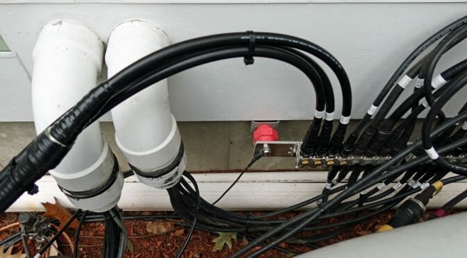
The body of the surge protector is a convenient contact point to connect the coax shield to the station ground before the coax enters the shack. If there is a short coax run between the surge protector and the radio this is adequate. If the run is much over 10m the voltage spikes will once again become offset and a second surge protector at the radio or station’s coax switch is recommended.
Surge Protector Designs
The majority of surge protectors use a Gas Discharge Tube (GDT) to clamp the voltage. GDTs in common packages are shown in Figure 1.
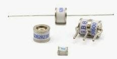
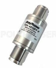
Figure 2 shows a typical coaxial surge protector.
The pill-shaped GDT is replaceable in some surge protectors. Most GDT devices are argon filled and are hermetically sealed so their trigger and clamping -voltages are not affected by humidity or atmospheric pressure. Below the trigger voltage argon is non-conductive, as the voltage increases the argon will become conductive as it begins to plasma. Once the current exceeds the plasma state the argon will go into an arc state where the clamp voltage can be as low as 15V at 20kA. This process occurs in < 1ns. Coaxial surge protectors are rated by maximum RF power. This is based on the “flash over voltage” rating of the GDT used in the surge protector.
A surge protector with a lower power rating (e.g. MFR-270 400 watts) may flash over and clamp at a lower voltage providing increased protection to the radio. It will also flash over and clamp when used with an amplifier at >400W and damage the amplifier since it will clamp (short) the RF output of the amplifier. It is important to use a surge protector rated for the RF power expected. Surge protectors with replaceable GDTs can be upgraded for higher power by replacing the GDT with a higher flash overvoltage.
“Surge protectors” can be found on-line that use a set screw to set a spark gap. They should never be used, the gap must be set very small to provide adequate surge protection. The flash overvoltage is unknown. It will vary with humidity and atmospheric pressure. Expansion with temperature or moisture may cause them to short out which will damage a radio or amplifier.
GDTs are available from Digikey for $1.25 each. I use GDTs with axial leads between the PSU outputs and from the outputs to the PSU case/ground, from each rotator wire to ground, and on other wires in and out of the shack. It is important to select a GDT with a higher clamping voltage than the wire it is protecting.
A GDT with a 75V flash over and 12V clamping will remain clamped on a +14V line once it is triggered. GDTs are not used on 110Vac or 220Vac power lines.
The surge protector is just one component of a station’s ground system. It does the job of keeping the center pin of the radio’s RF connector at the same voltage as the shield connection and therefore the radio’s chassis. Some like to think of the station ground as “fixed” at 0 volts, it is far from it during a strike. A typical strike is 10kA and can be 100kA or greater. A typical ground rod is around 5 ohms. The voltage at a single ground rod during a typical strike is 50kV (E=IR). The surge protector has clamped the coax’s center conductor and shield to roughly the same voltage protecting the input of the radio but this “same voltage” is on the order of 50kV.
The Surge Protector and Station Ground System
If the PSU and computer are grounded using the wall plug’s safety ground which terminates on the other side of the house at the service panel’s ground, which is near 0 volts, there will be a 50kV difference between the radio’s chassis and the components and DC wires to the PSU and through the radio’s USB components to the USB cable connected to the computer and damage will occur. The surge protector must be view as part of a grounding system.
A Ground System
Once the coax surge protector, power strip surge protector, radios, PSUs, amplifiers, computer, and anything else at the operating position are all connected to the station ground and to the ground rod they will ALL raise to 50kV together and damage may be avoided. The process of ensuring everything stays at the same potential is called “bonding”. It only takes one stray path to permit considerable current to flow through the equipment. That can be an arc to a lamp on the bench plugged into a different wall circuit or to a VHF coax that bypasses the station ground.
For a small shack, implementation is not difficult or expensive. I have a piece of ¾” copper pipe across the rear of the station bench with a series of ¼” bolt holes. Each piece of equipment including the metal Belkin power strip and the computer has a short ¾” wide braid connecting it to the pipe. Every cable, coax and wire has a MOV or gas discharge tube (GDT) connecting it to the pipe before it leaves the shack. The last non-bonded wire was the CAT-6 Ethernet wire which I replaced with a wireless Wi-Fi dongle.
The pipe is connected to the station ground rod which is also connected to the service ground. I do not want the fire risk of the bench arcing to the house wiring.
Other Advantages
An already low receiver noise floor was reduced by an additional S unit or more due to the grounding.
Hamilton, K1HMS
Hey Hamilton, that was a really nice and informative article. I had two additional questions/comments.
1) After everything in the shack has been bonded to the ground rod outside, what do you recommend for bonding to the house AC if you don’t have an obvious house ground anywhere?
2) Do you have a picture showing the interconnection between all the components you were discussing for a complete grounding system?
There are certainly a ton of books out there that discuss this, but getting feedback from people you know and can ask questions to is always more helpful I find.
73,
Brian AB1ZO
Hello Brian,
The station is bonded at the Single Point Ground (SPG), not the ground rod. The ground rod is connected to the SPG.
A quality metal cased AC surge protector (e.g. Belkin 10 socket) bonded to the SPG will prevent spikes on the AC lines from damaging the equirement. A 4 gang box with 4 standard duplex sockets and a Eaton 20kA surge protector is also a good solution. Either approach will work even in antique homes without third prong safety grounds. (Note the neutral wires still go back to the panel and the service ground.) The SPG and station ground rod must be connected to the service ground for safety purposes. The wire should be the same guage or larger than the AC feed line which is typically 14 or 12 AWG, to meet safety and code requirements.
The larger issue of tying the station and service grounds together for lightning protection is beyond the scope of this short reply. Whether lightning strikes the antenna or the power lines there can be a very large voltage difference between the two ground systems if their ground rods are well separated and/or not properly connected. While the bonded equipment may be safe this can create a risk to house and home.
Given a strike can produce a gradient of 1kV/ft along a 4 AWG wire due to L di/dt a long wire alone between the two ground systems is typically not sufficient.
I circumvented this problem by moving my shack to the basement adjacent to the service panel which permitted a short connection between the two ground systems. On a couple of installs we relocated the station ground rod and cable entry point to near the service panel and its ground.
As you wrote there are many good references including the ARRL Grounding Handbook and other online resources. A topic to watch for is “perimeter grounds”.
A quality metal cased AC surge protector (e.g. Belkin 10 socket) bonded to the SPG will ensure the AC lines are clamped to the SPG. This holds true in the case of antique homes with no safety ground.