
Several members of our club have been working on a High Altitude Balloon Project to promote STEM interest and learning by young people. Our project team currently includes the following folks:
Other interested club members are welcome to join us.
We want to provide a STEM learning opportunity and project to be planned and executed by young people ages 10 – 16. We are actively seeking engagement and support from local schools, Scout Troops and other youth organizations to help us with this project.
Our goals for the project include:
- Building and launching a high altitude balloon carrying Amateur Radio to near space and back
- Enabling young people to plan and execute the project with help and guidance from members of the Nashua Area Radio Club and supporting adults from organizations that wish to assist us
- Helping young people gain STEM-based experience and learnings by handling all phases of the project including:
- Planning the flight, the balloon, and its payload
- Building the balloon and testing it on the ground
- Launching, tracking and recovering the balloon’s payload
- Analysis of the flight data and the creation of a presentation to be delivered to fellow students and other interested groups
We plan to introduce new technology, experiments, and flight elements and develop team member skills and expertise across multiple launches. Later phases of the project are expected to include design and construction of additional payload electronics, high altitude/longer duration flights, and additional on-board atmospheric science experiments.

Our goals for the initial flight mission of this project will include:
- Building a helium filled balloon which carries a payload of < 4 lbs. to altitudes in excess of 90,000 ft (27,400 m)
- Parachute controls decent rate after balloon bursts
- Capturing a video of flight using on-board GoPro video camera(s)
- Flying an on-board APRS transmitter allows tracking from the ground via Amateur 2m APRS and aprs.fi
- Flight computer plus APRS provides altitude, position and temperature data throughout the flight
- Anyone with a device that has internet access and a web browser will be able to track the flight
- Augmenting the APRS system with commercial satellite tracker to assure successful recovery of our payload by the project team

The balloon is filled with enough Helium to carry its payload to a target altitude in excess of 90,000 ft and then burst. A parachute will deploy to control the rate at which the payload descends and will ensure a controlled safe and soft landing.

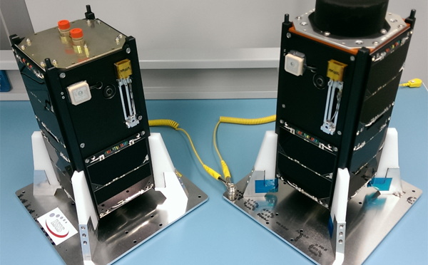
The payload will be built around a light-weight platform which will carry a Video Camera, a Flight Computer/APRS Transmitter, and a Commercial Satellite Tracker. The camera will capture a video of the flight and the flight computer will record altitude, temperature and position data and relay this information to the ground via APRS on 2m. A commercial satellite tracker would be included to ensure we could locate the payload once it is back on the ground.

A key part of the project will involve planning the target altitude and flight path for our balloon. There are some good resources available to help us do this. Check out the Balloon Performance Calculator here. Tools also exist to estimate a balloon’s flight path and track based on Jetstream and other flight parameters.
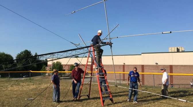
Once we launch our balloon, we can track it in flight via the Amateur Radio APRS network on 2m. The payload will transmit position and other information via APRS that will be received by the many APRS receiver stations that have been built by Amateur Radio Operators. The data from our balloon will be relayed to aprs.fi in real-time and will be able to be displayed on any device with internet access and a web browser.

Once we recover our balloon payload, we will guide our young team members in analyzing the data from the flight to help them to learn about atmospheric conditions and to prepare to share the results along with the video captured with classmates and other interested groups. You can get an idea of the video that we can expect below.
We are working to raise the necessary funds to support our project. We are counting on the generosity of our members and friends to help us. Please consider making a donation here.
Fred, AB1OC