The ARRL organized a National Parks on the Air program (NPOTA) in 2016 that made operating portably extra fun. But you don’t need a special event year like this to have a reason to get out and make QSOs. There are other programs that operate continuously that are good draws for these far away places. I made several trips to Boston Harbor Islands in 2016 to celebrate NPOTA, and help operators put some QSOs in the log for other awards programs as well. Here are a couple of programs that will continue long after NPOTA is over:
The British program Islands on the Air (www.rsgbiota.org) gives participants an opportunity to collect islands much like the ARRL’s DXCC program collects countries (entities). As it turns out, because there is no commercial power (mains) available to the public, the Boston Harbor Islands are somewhat rare (being claimed by only 30.2% of IOTA participants). It is a lot harder to get on the air and be heard when it is only battery and solar power driving things. That makes the challenge even more fun. And, when you are heard, you’ve often got a pileup!
The US Islands Awards Program (www.usislands.org) is similar to the IOTA program, except it accepts islands anywhere in the United States. (The IOTA program only counts islands that are true “sea” islands.) Lovells Island in Boston Harbor has the designation MA042S, and I was lucky enough to be the first to activate it for this program.
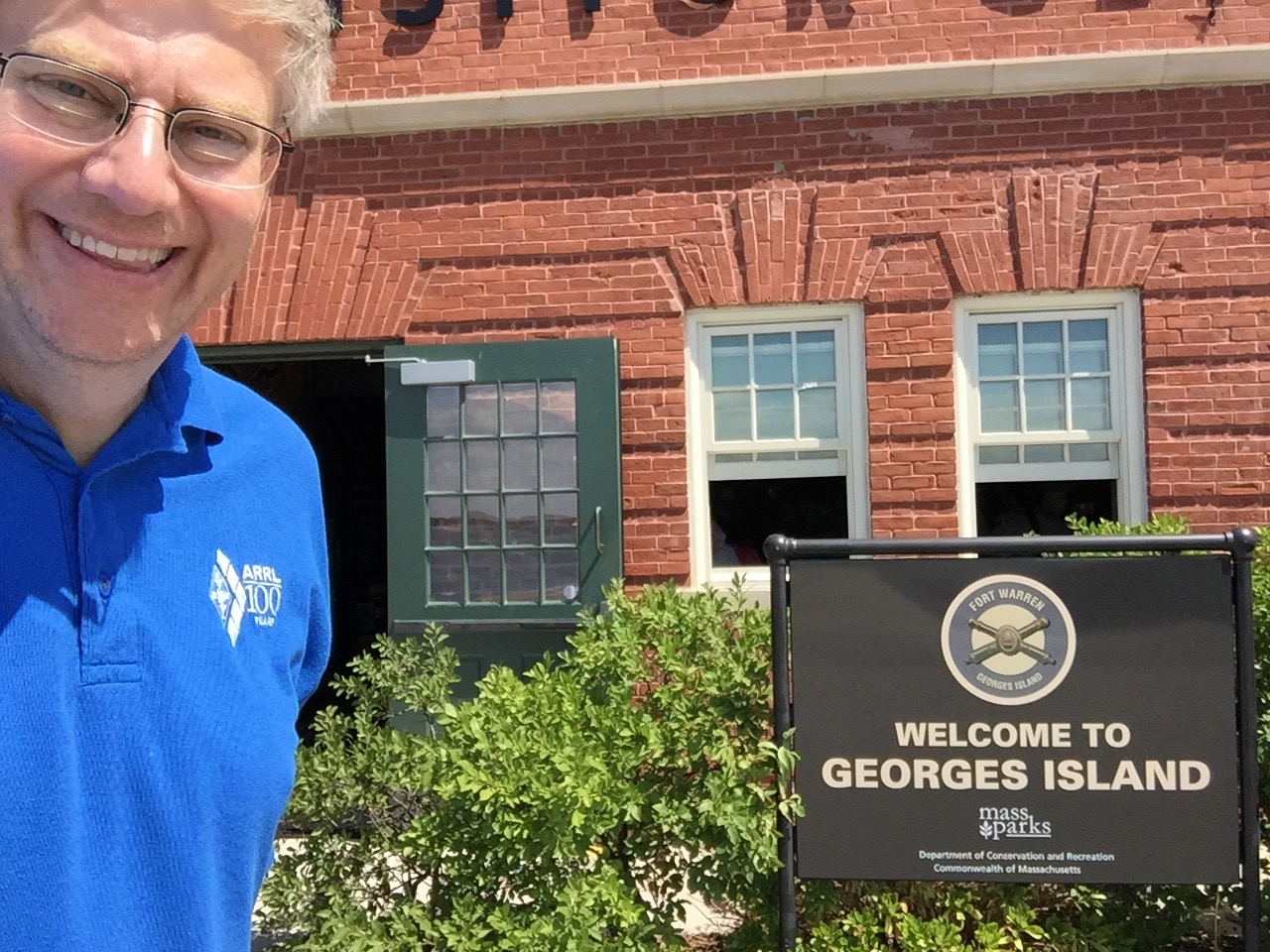
These mini-DXpeditions to Boston Harbor Islands begin at home, sorting, selecting, and packing the items needed for a successful activation. For day trips to Georges Island, the largest of the group, and the main destination for the Boston-to-island ferry service, I concentrate on packing just the bare essentials of radio, antenna, coax, rope, and so on.
Georges Island is about an hour long ferry ride from Long Warf in Boston, and it has been built up quite a bit just in the last ten years. It how has a snack bar, a new play area for young children, and hosts many festivals and events during the summer. The boats that once carried only a handful of passengers ten years ago are now often full of families and groups. Everyone is friendly, and more than once I’ve had help from my fellow voyagers with my gear.
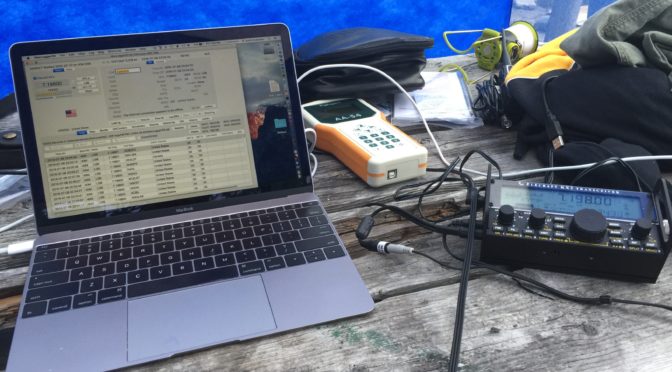
Once off the boat on Georges, I hike quickly to a picnic table near a tree. No trees on this island are very tall, so there are no prospects for running wire dipoles or other wire antennas. Instead, I build a vertical antenna from a mini-Buddipole (www.buddipole.com) kit. I will often lash the shock-cord mast to one of these short trees to hold it up. The wires from my home-brew four-wire radial kit also serve as guys for the setup. Assembly is usually quick (under ten minutes) and a quick check with an antenna analyzer confirms the antenna is resonant.
In previous years, daytime operations were typically on 20m, 17m, or 15m. Because of changing propagation conditions, in 2016 I only operated almost exclusively on 20m. Selecting an operating frequency can be a challenge when operating QRP. I’ve often been “pushed off” my calling frequency by another operator that likely couldn’t hear me. Oddly enough, I’ve had good luck operating near the top of the 20m band, well into the General segment, which has the additional benefit of increasing the number of people who can call you.
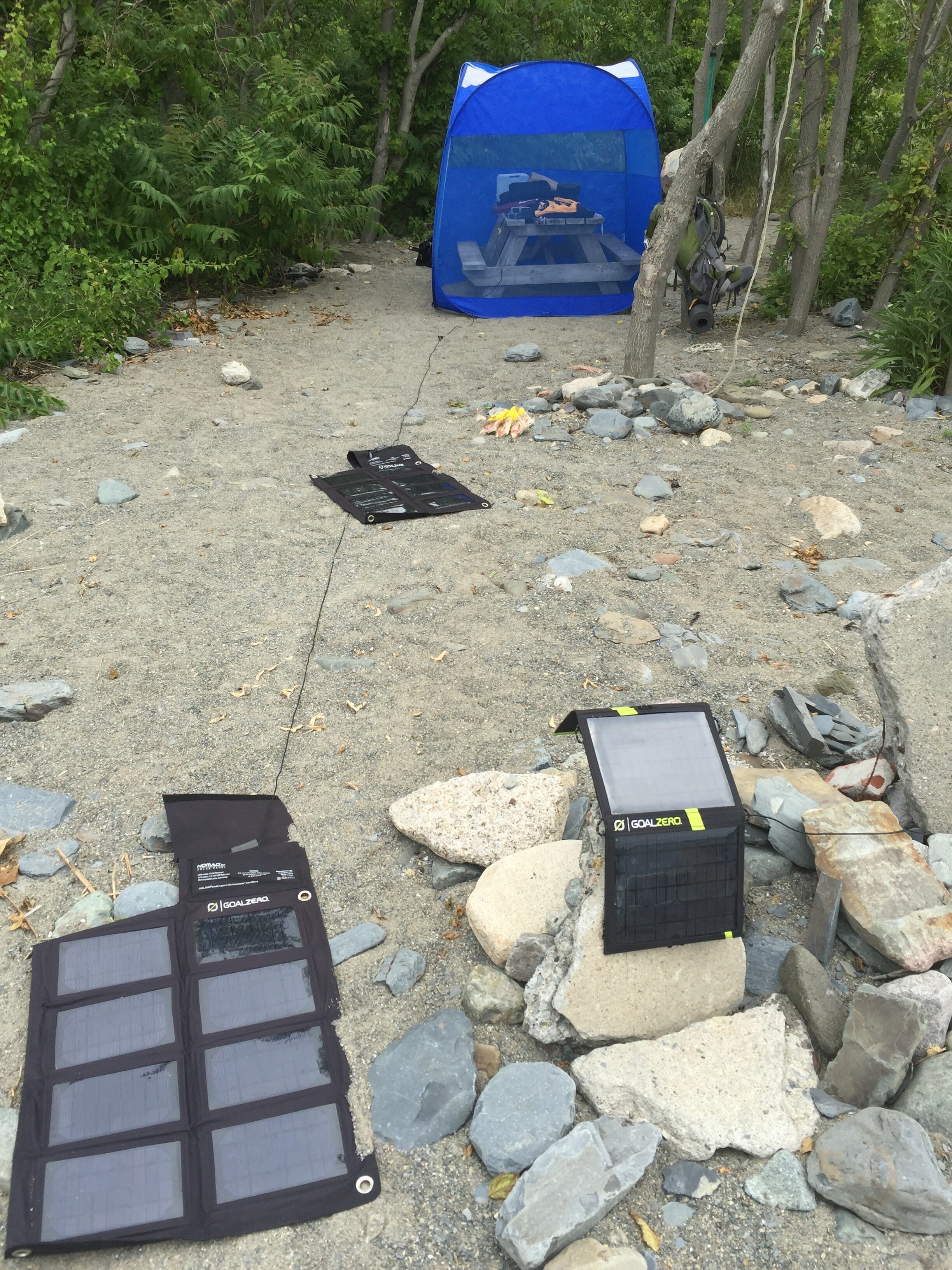
Day trips with only a couple of hours of operation need only a battery, but I find that I bring a solar panel out of habit. With the panel connected, I usually leave with my battery fully charged. Running without the panel would also work, but I’m unwilling to take a chance that my day would be cut short because of power problems.
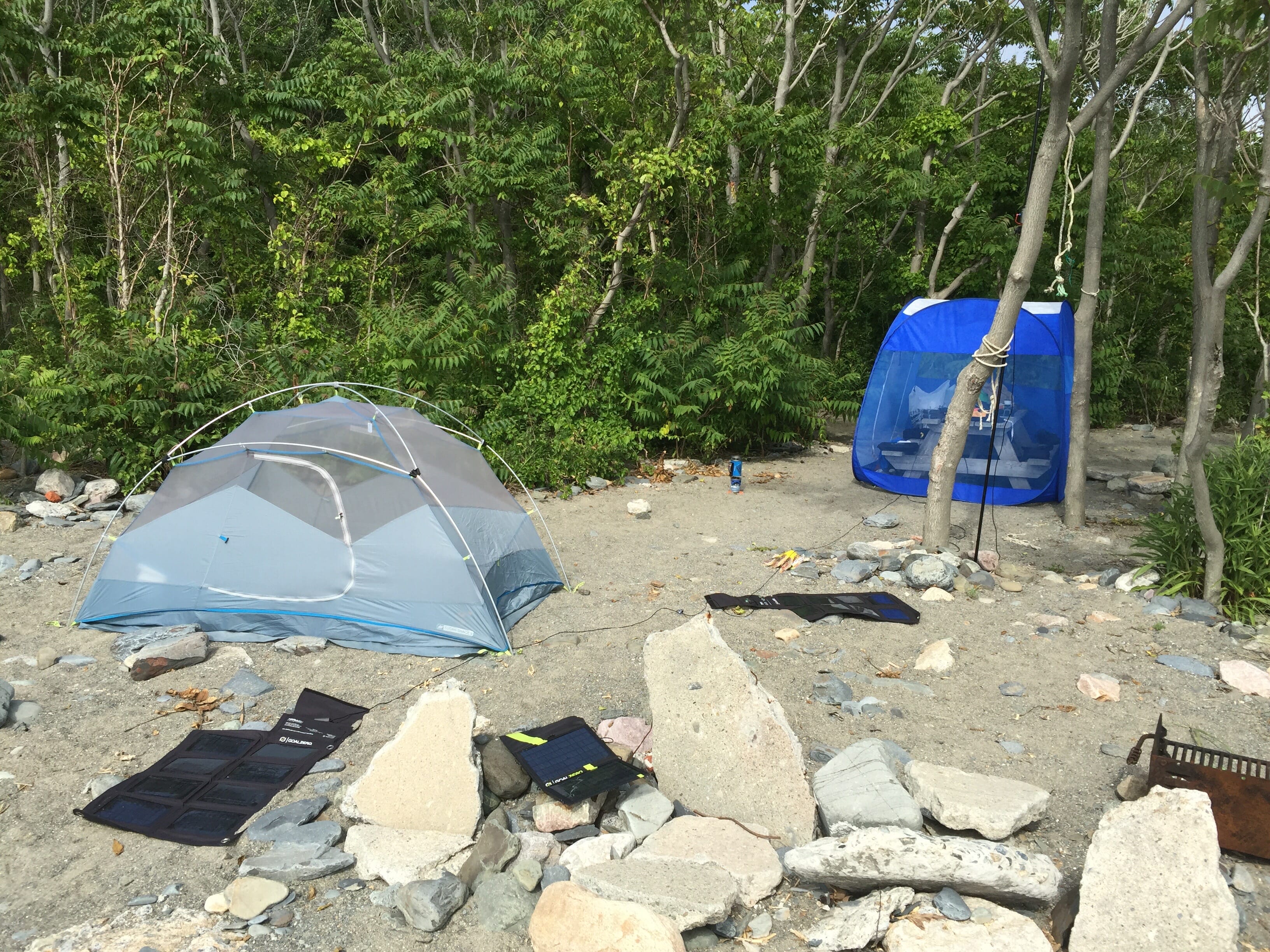
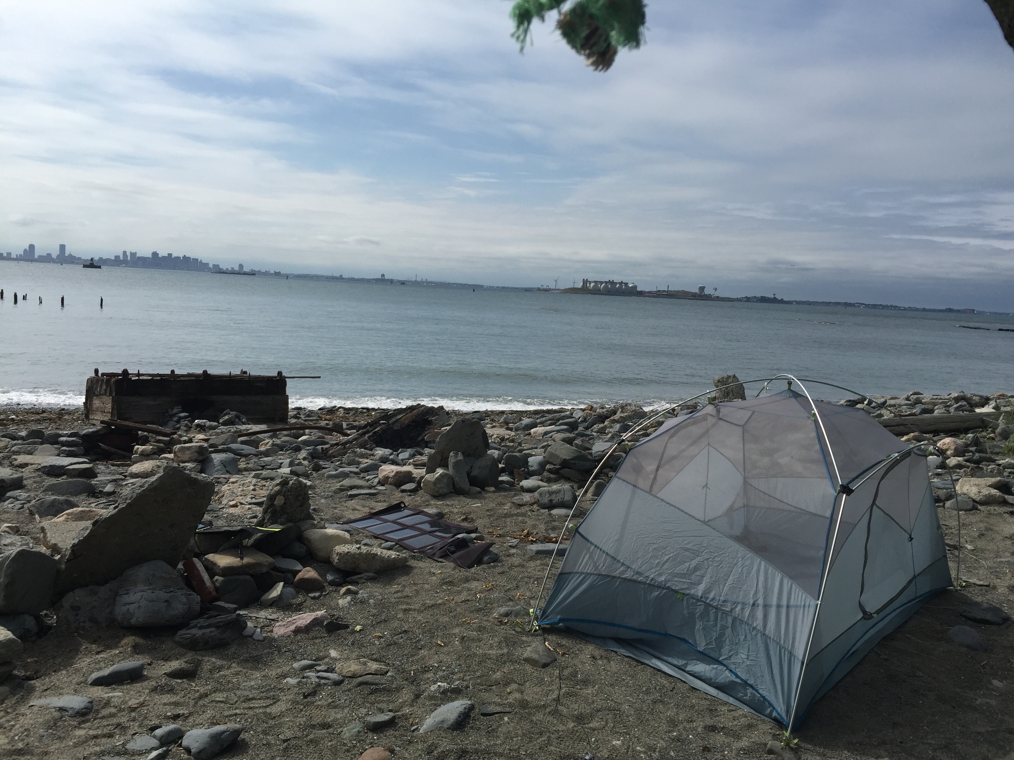
Camping trips are more involved. Lovells Island is the only place that both counts for the IOTA program and provides campsites. You need to plan ahead as campsites are allocated on a first-come-first-served basis, and reservations begin in January. I am rarely able to reserve all the dates I would like, and choosing dates seven months in advance means you’ll never know what kind of weather you’ll encounter. A severe thunderstorm over one of these islands is magnificent and terrifying!
Getting to Lovells is also more difficult. The ferry shuttles between Georges Island, a few other large islands, and Boston Harbor’s Long Warf. Connections to Lovells Island are made from Georges, and only occur three times per day. Once that last boat has left, you are stuck on Lovells until the next morning. You better have everything you need! That includes food, water, first aid supplies, power for your phone and radio, and anything else needed for a successful camping trip.
[huge_it_maps id=”1″]
Lovells Island is covered in trees, many of them tall enough to easily support a wire antenna. That sounds convenient, but how long did it take you to hang your last wire antenna at home? Was it a several hour operation with a couple of friends? Given the short time available during one of these trips, I bring a backup antenna in case the wire antenna cannot be hung successfully (or hung high enough). My tool of choice is a throw weight and line like those used by arborists. Though the lead filled leather bag is heavy, it is compact and effective for getting a rope through a tree. An end-fed half-wave (EFHW) antenna is a good choice for this duty since it only requires one line high in a tree. The remainder of the wire that isn’t hung vertically can slope down to the ground and be tied off.
I’ve had good luck with two EFHW antenna models. PAR EndFedZ antennas (www.lnrprecision.com) offer a trail-friendly antenna good for 10-20-40m that easily handles QRP power. This packs small and is light.
Intrigued by an advertisement on the ARRL website, I ordered and tried the MyAntennas (www.myantennas.com) EFHW-8010, a multiband antenna good from 80m through 10m that can also handle high power. On my last camping trip, I was very lucky to get my first throw through the tree in a good spot, and this EFHW antenna was up and running in about thirty minutes. It performed very well and will be in my pack on future trips.
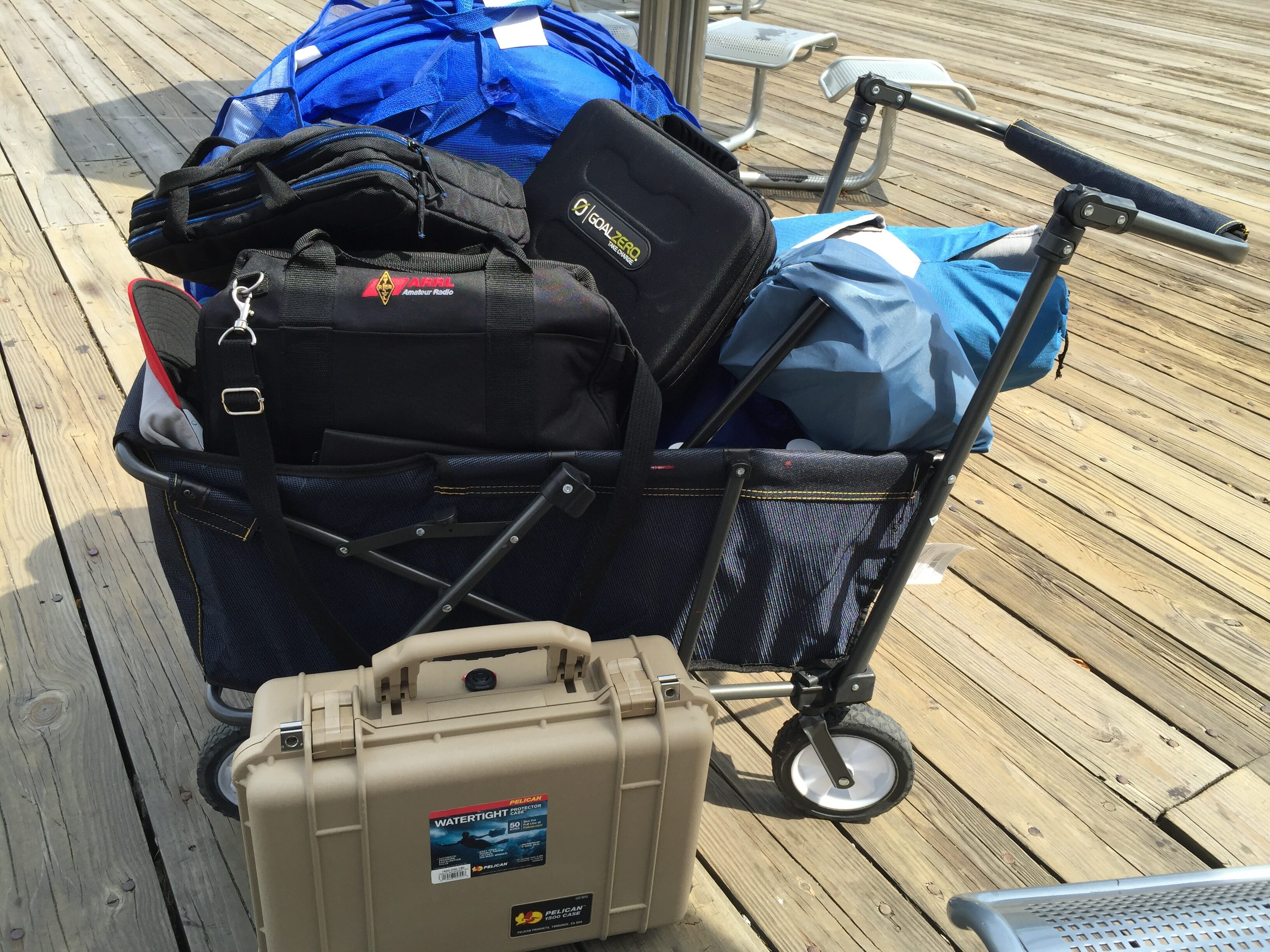
Camping on Lovells is primitive. The park service offers chemical toilets, and cleared areas with picnic tables, but nothing else. You must bring your own water. Budget at least a gallon a day, and more if it’s hot. Suddenly, a three-day camping trip can get bulky and heavy! I’ve tried several “beach carts” and may have finally found one that is robust enough to handle the weight of all my gear, and the rough terrain of the island. Remember to bring everything you need to pack out your trash, too. Good campers leave nothing but footprints.
Prior to each trip, I will array everything to be taken on the floor, and I’ll perform an inventory, thinking through each step and each thing that must be accomplished. Forgotten rope or even a forgotten connector might ruin an operation. Once everything is counted, the cart and my large backpack are filled.
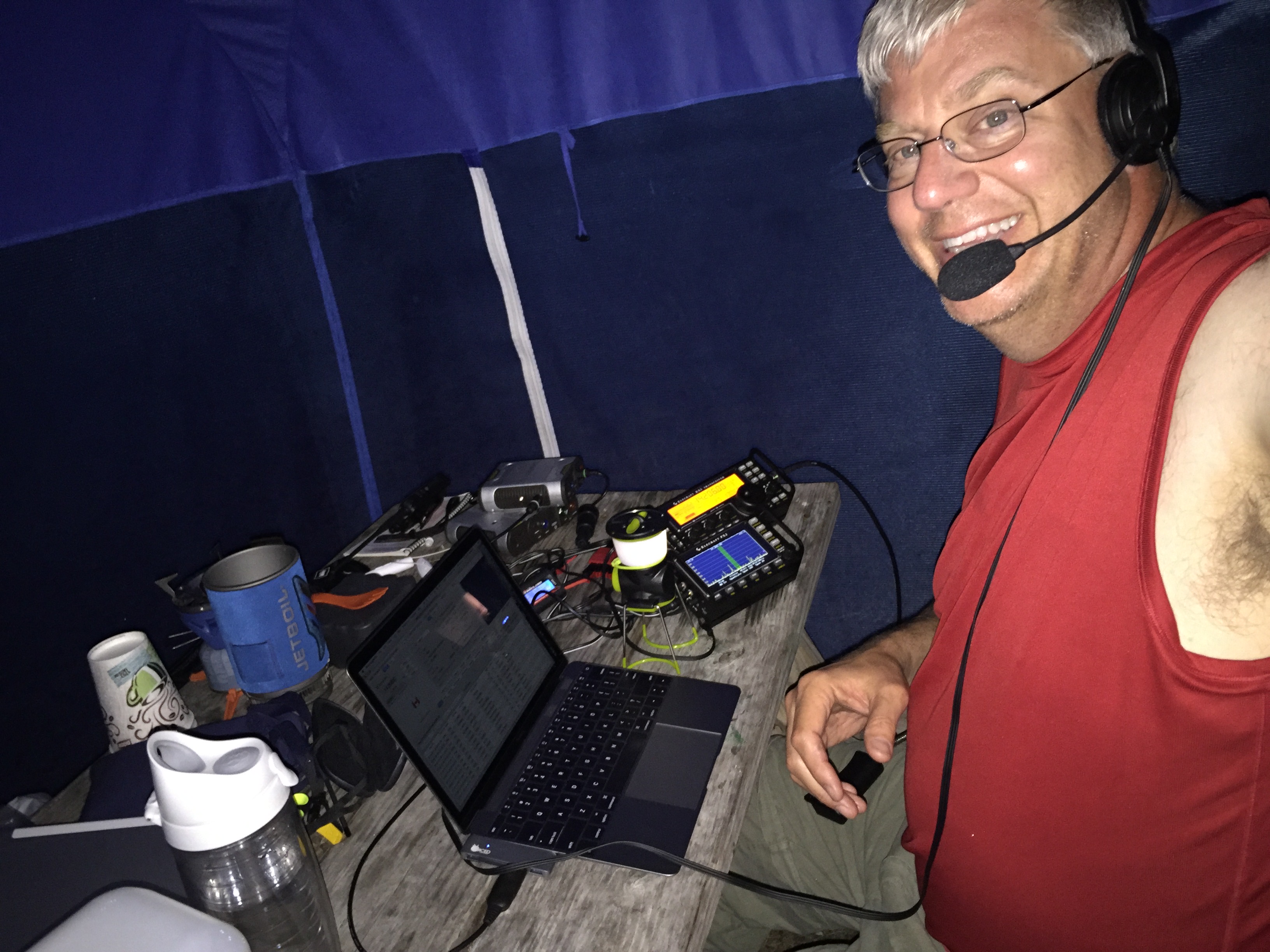
Operating begins after camp is assembled, and I’ve had a short rest. These trips often happen in July or August, and it can be hot and sticky on these islands. Beware dehydration and overheating. When operating in a remote area, help may not be just a phone call away. It is important to take care of yourself first.
In three trips out to the islands in 2016, including two camping trips, I made 343 QSOs to 18 DXCC entities and 42 states. I’m going to work on completing my Worked All States award from these islands next year! That said, it isn’t just my awards program that keeps me going. I know that I’ve made it possible for other hams to work these islands for the IOTA program, the US Islands program, and even Worked All States. It is gratifying to hear, “Thanks for the new one!” several times during each trip.
I’m already planning next year’s trips. I operate as NE1RD/1 and have a fine QSL card that I would love to send to anyone I work. While Boston Harbor Islands are not exactly exotic, they are beautiful, and the act of planning and executing these excursions has made me a better DXpeditioner, and I believe a better operator.