
As I sit here watching the N1FD teamwork the CQ Worldwide DX contest, it got me thinking about what contesting is really about and why we contest.
Let me try to answer the second question first. There are lots of different reasons to operate in contests. Many folks do this to work new countries, states, zones, islands, grids, etc. It seems that you can find a contest that is designed to create opportunities to work just about anything that you can think of on the bands. Others work contests to try to test out their stations and to improve their skills as operators. Of course, many folks compete to win the contest or to place better than they did the last time. Some may even compete to set a record.

Perhaps the best reason to contest is that it provides one of the best opportunities to be a better operator. You may say, aren’t contesters just QRM on the bands on weekends when we want to use them for other stuff? I can see why some feel this way. I wish that more amateurs who feel this way would take some time to listen more closely to what is going on during the contest.
There is nothing quite like listening to a skilled operator work a pileup from a rare place during a worldwide contest like CQ Worldwide DX. Such an operator will make 100’s of calls in a row. They will accurately get each caller’s information into their logs and the really great ones will also use their skills and energy to ensure that each of their callers gets the contest station’s information correct in their logs as well.
This requires great skill in many areas. First, you need to really learn to listen and to pick out weak and fading callers in the presence of a great deal of QRM. It’s often necessary to piece together a good callsign using several rounds of a QSO. Good contest operators know perhaps 500 or more of the most common calls used in their contest and this information helps them to recognize calls and avoid making errors. The great ones also know how to work with each caller to ensure that they get the correct information to complete the contact and that the other operator does the same.

I like to think of this as getting in the head of the other person during the QSO. Did they get my call right or do I need to slow down and say my call again? Did I hear their callsign and exchange correctly or do I need to give them a chance to ask me to correct something for them? While I am doing all of this, I need to be as fast and efficient as possible. These skills take a great deal of practice to develop. You can get there with less time in the chair during contests if you take some time to listen and pay close attention to the great operators that you will hear during contests. First and foremost, great contesters are great listeners and they can accurately pick out call signs on the first try without making mistakes.

What, you say that any operator will do great when they are sitting at a big contest station with a lot of power and big antennas? It is true that having a well-built station and good hardware and computers helps make contacts easier. Computers and modern software like N1MM+ also play an important role in making the mechanics of finding and making contacts accurately more efficient. The contest community makes their software available free of charge to everyone. I strongly encourage anyone who contests to set up and learn to use modern contest software. While these tools help, they are just like construction tools in the hands of a carpenter. The master carpenter can create a work of art with a hand saw, a hammer and some basic hand tools while an apprentice can struggle to get good results from the best shop and tools available.
Also, most contests are designed with categories to group contesters with their peers who have setups similar to theirs. Station hardware differences also do not account for the contester who goes to an island in the Caribbean with a 100W radio and a simple antenna and wins an award in a contest.

We also saw this clearly during the WRTC competition here in New England a few years ago. We had the best operators in the world competing using the exact same towers and similar antennas that we use for our annual Field Day operation and they made 2,000 or more contacts in a 24 hour period using 100W radios. Many of these operators did this while making almost no mistakes!
So what else makes a great contest operator besides working fast and efficiently to complete and log lots of contacts accurately? For one, these folks know a great deal about propagation and how to take the best advantage of the conditions at hand. They know when it’s time to run on 20m into Europe, when to look for Japan on 15m for those multiples, what time of day and segment in the contest to focus on contacts in the Caribbean and South America, etc. They learn when they need to change bands and when it’s time to work multipliers or tune the band that they are on with their second radio or VFO. They can quickly determine the band and propagation conditions on the contest weekend and adjust their strategy to take the best advantage of the conditions at hand.
A great operator also learns to make the best use of their station and antennas. They understand where their stations work well and they adapt their approach to a contest based upon this. They also spend lots of time looking at and comparing their performance from contest to contest and against other competitors in the same contests to see where they can improve.
So what if you don’t really want to win contests? Why would you bother with this? The most important reason is that contesting will make you a better operator. You’ll learn to hear that really weak DX and get them into your log accurately. When you get on the air, you’ll be an operator that others want to work because they know you will help them complete a contact that they want. You will find and work stations that most others will miss. In short, a bit of dedication to contesting will make you a great operator.
")
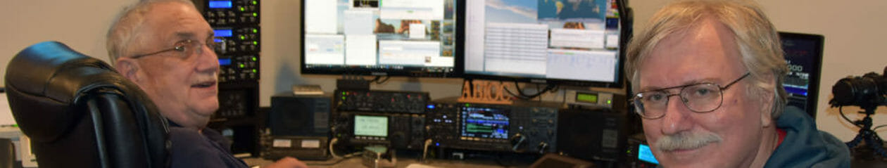
As the CQ Worldwide DX Contest weekend draws to a close, I’d also like to add that I am proud of the job that the operators in our club did at our station. Most of them had almost no DX contest experience before this weekend. They worked the contest hard and have made contacts to over 100 counties in about 40 hours of operating. They have all improved their skills greatly and I look forward to working all of them at any time.
73, and see you in the contest!
Fred, AB1OC