Tag Archives: Mentor

Yagi Antenna Teaching Construct Part #3: Directional Gain and Front to Back Ratio

In this final article of our series on the “Lego-style” antenna for teaching basic antenna physics and behavior, our focus is a Yagi-Uda 3-element antenna for 2 meters. The Yagi antenna is the most common construction form for a “beam” antenna. The Yagi has high gain in one specific compass (azimuth) direction and very low gain in the opposite direction when compared to the classic 1/2 wave dipole. The Directional Forward Gain and “Front to Back” Ratio (F/B Ratio) features are hallmarks of the Yagi and the reasons for its high popularity. The forward gain dramatically increases “Effective Radiated Power” in a chosen direction; the Front to Back Ratio dramatically reduces interference from signals to the antenna’s backside.

BASIC PRINCIPLE OF THE 3-ELEMENT YAGI ANTENNA

The Yagi antenna shown in the Feature Picture above has 3 radiating elements. The center element (with the coax attached) is the “Driven Element” (DE) receiving RF energy from the transmitter.  The other two elements are “parasitic”, meaning they are not connected to the transmitter. These elements absorb energy from the DE RF wave and re-radiate it by Faraday’s Law of Induction. This fact gives both parasitic elements a 180-degree phase shift relative to the DE. In the above picture, the left side element is the Reflector, typically 5% longer than the DE; the right side element is the Director, typically 5% shorter than the DE.  The length differences make both elements slightly off resonance to the DE RF wave which adds a second phase shift relative to the DE. Finally, the distances on the boom between the DE and parasitic elements adds a third phase shift since it takes a finite time for the DE wave to reach the Reflector and Director.  The distance between the DE and the parasitic elements vary between 0.1 to 0.25 wavelengths depending on materials, construction details and design goals for the forward gain and F/B Ratio.

The Yagi secret is that the sum of these three phase shifts for the 3 elements add in a way that reinforces each other for RF energy moving towards the Director. However, RF waves moving towards the Reflector combine in a way that subtracts and leaves little RF energy.

Figure 2 provides an illustration of this action using only waves interacting between the DE and Director, for simplicity.
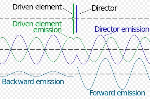
Yagi Antenna PhasingFigure 2.  Summing RF wave from the Driven Element with the Induced wave from the Director Element (from Wikipedia, Yagi-Uda Antenna)

The DE RF wave (in green) reaches the Director parasitic element and induces a second RF wave (in blue) by Faraday’s Law. The multiple phase shifts that make up the Director RF wave gives a forward moving emission that adds to the DE wave yielding a combined larger RF wave.  However, the Director RF wave moving back towards the Reflector is nearly 180 degrees out of phase to the DE wave and the two nearly cancel each other out.  A similar analysis at the Reflector element shows that Reflector waves moving towards the DE and Director also adds to their waves to create an even larger wave. However, Reflector waves traveling off the rear of the antenna subtract with waves arriving from the DE and Director yielding very little RF energy leaving the backside direction of the antenna.

THE TOOLBOX FOR OUR EXPERIMENTS

The top Feature Picture shows the “Lego-Style” antenna in a Yagi assembly and the Lamp Bridge Receiver ½ wave dipole antenna is seen in the upper right corner. The Lamp Bridge Receiver lights when resonant RF is sensed and we used this tool in both Parts 1 and 2 of this article series.

New to our toolbox is a breadboard circuit to measure RF power in a semi-quantitative way using an LED Bar Graph display. The breadboard was built on an Analog/Digital Trainer Module and is seen in the lower right corner. The circuit samples the RF signal received by a 1/4 wave antenna (black antenna seen behind and above the breadboard). The induced RF current is converted to a dc voltage that feeds to a 30-stage linear increasing voltage comparator circuit.  A comparator turns on an LED when its voltage threshold value is reached. Our circuit is using only 15 LEDs due to breadboard space limits; however, by skipping every other comparator we are still measuring a 30 fold signal range. The picture shows 3 lit LEDs indicating a sensed voltage that is one-fifth the dynamic range of the circuit.

EFFECTIVE RADIATED POWER: COMPARING THE DIPOLE and YAGI-UDA ANTENNAS

A)  BASIC DIPOLE PERFORMANCE

We will use the classic 1/2 wave dipole as the benchmark to assess benefits of the 3-element Yagi-Uda antenna.  We begin by measuring relative radiated power of the dipole as we increase transmitter power stepwise between 5, 10, 20 and 40 watts.  The power detector circuit consists of a standard 1/4 wave stub antenna connected to the LED Bar Graph RF meter.  The results will be used to “calibrate” the detector circuit and be our reference point when we calculate Yagi Gain.

The video below explains the use of the LED Bar Graph RF meter; then it shows the actual testing protocol and you can see the LEDs report received RF signal as we increase Tx power to the dipole.

The results of received RF signal versus transmitter power for the dipole antenna are summarized in Table 1.  The data show a close to linear correlation (as expected) within the semi-quantitative limits of the Bar Graph Display.


Display Calibration

B)  3-ELEMENT YAGI PERFORMANCE

The next video shows the antenna forward radiated power as we stepwise build the Yagi beginning with the basic dipole; the addition of the Reflector element and a third addition of the Director element.  Note, the Tx power is constant at 5 watts.  Details of the Yagi construction (element lengths, spacing, etc.) are given in the video.

The data for the RF radiation received with the stepwise addition of elements to assemble the YAGI antenna are summarized in Table 2.

Yagi Antenna ERP

There is a significant increase in antenna forward received signal (looking towards the direction of the Director) as we add the two parasitic elements.  The signal increases by 3+ fold with the Reflector over the dipole and then by 7+ fold for the combination of Reflector plus Director. However, we want to translate the results to customary power level values in decibels.  The combined data of Tables 1 and 2 let us do this as an estimate of Directional Forward Power.

Gain for 2-Element  Antenna in dB:
7 Lit LEDs at 20 watts for dipole and 5 watts  for Yagi
dB  =  10 x Log(20/5)  =  6.0 dB  (= 1 S meter unit)

Gain for 3-Element Yagi in dB:
15 Lit LEDs at 40 watts for dipole and 5 watts for Yagi
dB  =  10 x Log(40/5)  =  9.0 dB  (= 1.5 S meter units)

THE FRONT TO BACK RATIO OF EFFECTIVE RADIATED POWER FOR THE 3 ELEMENT YAGI ANTENNA.

A)  THE 1/2 WAVE DIPOLE

We begin our experiments on Front to Back received power using the basic 1/2 wave dipole as we did above for forward radiated power.  However, since the dipole is symmetric side to side we will label our measurements as “left side” and “right side” to the wire axis. Second, our dipole experiment will use the Lamp Bridge Receiver antenna because we will use power levels not requiring amplification (the LED Bar Graph RF meter has a 10x gain built-in). Also, resetting the LED RF meter at the opposite table end is not easy.

The 2-sided picture below shows the responses of the Lamp Bridge Receiver antenna to a 40-watt transmission.  Picture 1A shows the received signal on the left side of the dipole; Picture 1B shows the response on the right side of the dipole.

Yagi Antenna Pattern

As you would expect, the radiated power of a basic 1/2 wave dipole appears equal broadside to the wire axis, as we learned in the Technician License Class.

B)  The 3-Element YAGI-UDA Antenna.

Our last video has a simple experiment showing the Front to Back Ratio effect of the Yagi antenna for radiated power parallel to the boom axis.  We return to using the LED Bar Graph RF meter for the experiment. The study is made easy by the simple trick of swapping placement of the Reflector and Director elements, a benefit of the “Lego-Style” construction of our antenna model.         

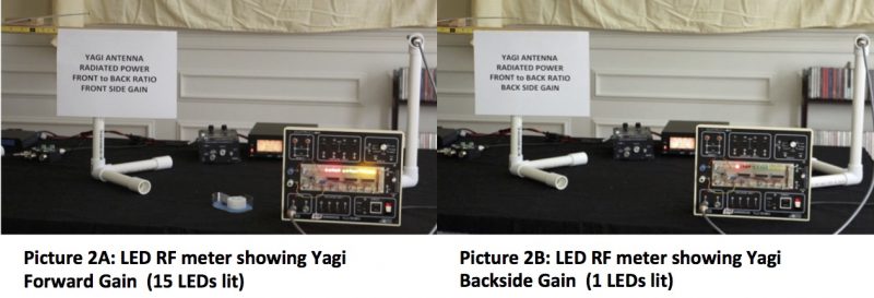
The study results are striking.  The data for the Forward RF signal from the Yagi showed an 8x fold increase over the basic dipole with 15 lit LEDs at 5 watts for the Yagi versus the dipole needing 40 watts to elicit the same response. We also saw this result in Video 2 (compare data in Tables 1 and 2). In contrast, the received Back-Side RF signal gave only 1 lit LED.  The difference merits visual repetition with a paired picture display.

Yagi Antenna Pattern

We can transform this data to estimate dB Power Gain of the Back-Side signal in a similar fashion as the Directional Forward Gain.  Again, we use data from Tables 1 and 2.  However, we need to interpolate the signal response of the Yagi Back-Side signal of 1 LED with the 2 LED response for a dipole at 5 watts. The factor is 1/3, not 1/2. Why?   Remember, the RF detector circuit divides the received signal into 30 equal size buckets, but we only look in every other bucket with an LED.  Hence, LED #2 measures the third bucket, not the second bucket.   I will repeat the Forward Gain calculation here to make the result comparison easier.

Forward Gain for 3-Element Yagi in dB:
15 Lit LEDs at 40 watts for dipole and 5 watts for Yagi
dB  =  10 x Log (40/5)  =  9.0 dB   (1.5 S meter units)

Backside Gain for 3 Element Yagi in dB:
1 LED (Yagi) = 1/3 (5 watts) =1.7 watts
dB  =  10 x Log (1.7/5 )  =  –  4.6  dB

We now can easily calculate the Yagi Front to Back Ratio:
F/B Ratio  dB  =  9.0  dB  –  (-) 4.6 dB  =  13.6  dB
(Remember, dB is a logarithm value, so we subtract the 2 numbers, not divide them)

C)  Results Analysis

The result of 9.0 dB for Yagi Forward Gain is likely high considering an expected typical range of 6 to 8 dB (seen in commercial units).  The estimate for the F/B  Ratio of 13.6 dB seems low, again based on typical commercial units that can have an F/B of about 20 dB.  However, the cited values are for “Far Field — Free Space” conditions; conditions not simulated in a 20 x 20 ft. room in my house.  Also, the experiments made no effort to optimize Forward Gain or the F/B Ratio by element lengths and spacing.

The list of experimental error sources in our studies are many; a partial list includes detector circuit layout that combined RF, digital and DC signals on one board, the accuracy and precision limits of discrete LEDs, antenna height above ground issues and wall-plus-apparatus surfaces that both absorbed and reflected RF signals.

Still, the “Lego Style” Yagi Antenna Assembly permits an easy way to demonstrate many basic antenna properties while showing performance results that are reasonable.  Perhaps, the next ham adventurer to design Version #3 will expand experimental versatility and improve performance areas.

I hope this series of three articles has expanded antenna knowledge to newly minted hams and has re-kindled interest in antenna experimentation for more experienced hams (many more knowledgeable than me).  Coming full circle to my thoughts as I began this article series, our antennas are the magic carpet that we ride over the airwaves whether to friends across town or to that rare DX station 10,000 miles away.  Enjoy the Ride!

I owe a heartily thank you to Skip Youngberg (K1NKR) for reviewing my draft manuscript for Part #3 and contributing valued suggestions. Also, the complete series of three articles could not have happened without the multi-media assistance, encouragement and full support from a special YL, Teresa Mendoza.

73,

Dave N1RF

N1FD Enters The CQ Worldwide DX Contest In A Quest To Earn DXCC!

The CQ Worldwide DX SSB Contest has just completed and we made a big step toward our goal of earning an ARRL DXCC Award for our club call, N1FD.

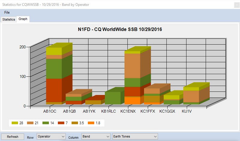
DXCC - N1FD Operator QSOs and Bands
N1FD Operator QSOs and Bands

The following club members operated as N1FD in the contest:

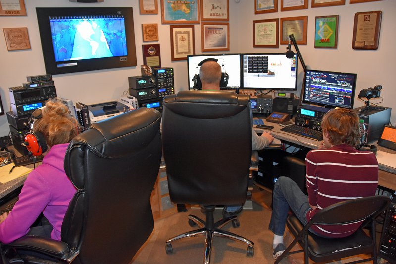
The N1FD Team operated from our station (AB1QB/AB1OC).

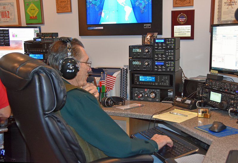
DXCC - Joe KB1RLC in CQ Worldwide DX at AB1OC
Joe KB1RLC Operating  in CQ Worldwide DX at AB1OC

Many of the club members who joined us had not previously had the opportunity to operate in a major DX contest. Our approach to the contest included a significant amount of time spent to help folks learn how to operate in a major DX contest such as CQ WW DX. All of the members of the N1FD Operator Team did a great job and we worked a lot of DX given the relatively poor band conditions throughout the contest period.

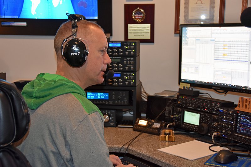
Hard at work on our DXCC - Our N1FD Multi-op Teams In Action (KC1ENX, KC1FFX, and KC1HHX)
One Of Our N1FD Multi-op Teams In Action (THe Funchum Team – KC1ENX, KC1FFX, and KC1HHX)

We entered the contest as N1FD in the Multi-Op, One Transmitter category and we operated in the High Power, Assisted class. This category allowed us to have two transmitters on the air on different bands simultaneously. One transmitter was the “run” station from which we could call CQ and contact any new callsigns on a given band. The other transmitter was a multiplier only station which was only allowed to work new multipliers (new DXCCs and CQ Zones) on a given band. We had both stations on the air simultaneously for a good portion of the contest period.

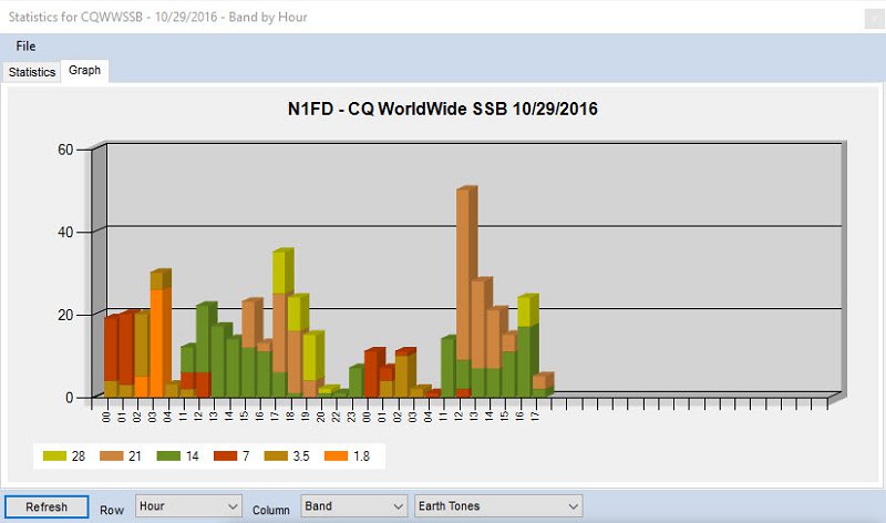
DXCC Progress for N1FD During The Contest Period
N1FD QSOs During The Contest Period

We operated on all of the contest bands from 160m through 10m during the contest. We mostly operated in Search and Pounce mode to focus on maximizing the number of DXCCs and CQ Zones worked. Search and Pounce mode also made it easier for the less experienced folks on our team to learn about contesting. We used a mix of data from the spotting cluster and tuning the bands to find and work stations. We did a bit of operating in Run mode (calling CQ) as well to help put additional QSOs in our log to boost our final score and to learn how to operate by calling CQ in a contest.

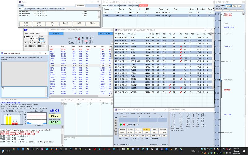
N1MM+ Logger Setup For Our DXCC Quest
N1MM+ Logger Setup For Our Contest Operation

We used the N1MM+ logger in a multi-op, networked configuration during the contest. This allowed us to share a single log between our two stations and to keep track of the multipliers (DXCCs and CQ Zones) that the combination of the two stations worked during the contest.

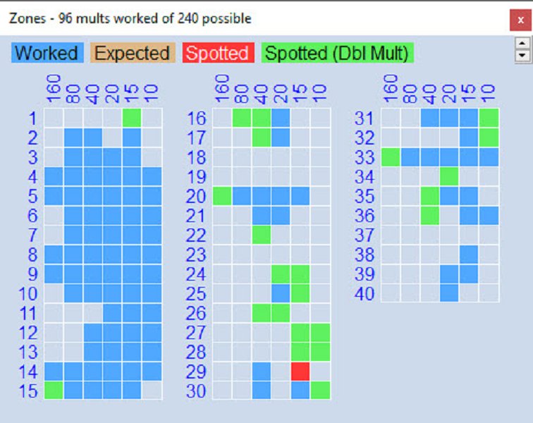
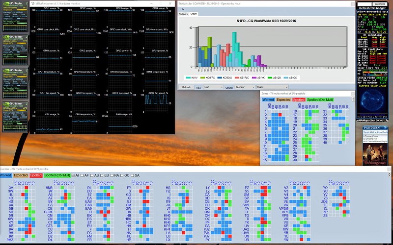
Final DXCCs Worked By The N1FD Team
Final DXCCs Worked By The N1FD Team (DXCCs worked are in Blue)

We worked a total of 108 countries in the contest and brought the total DXCCs worked by the N1FD callsign to 121.  This means that we worked a complete DXCC during a single weekend! We added 40 new DXCCs worked as a result of our contest operation.  Before the contest, our club call had 62 confirmed countries. We will need 38 more confirmations to qualify for the ARRL DXCC Award. We have received a total of 16 of the needed 38 new DXCC confirmations via LoTW as of the end of today!

We also gave our club a good start toward earning future 5-Band DXCC and DXCC Challenge Awards as we worked a total of 283 band-points during the contest.

Final CQ Zones Worked By The N1FD Team
Final CQ Zones Worked By The N1FD Team (Zones worked are in Blue)

We also made progress toward earning our CQ WAZ (Worked All CQ Zones) Award – we now have 33 our of 40 zones worked and 28 confirmed.

Our Final Claimed Score Summary
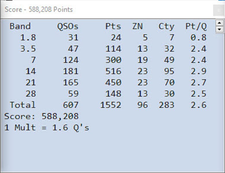
Our Final Claimed Score Summary For The Contest

We made a total of 607 QSOs during the contest for a claimed score of 588,208.  The actual score may be lower than this after the contest adjudication process completes in several months as deductions will be taken for any incorrect calls or exchanges. You can also see our results at the 3830 Score Rumor website.

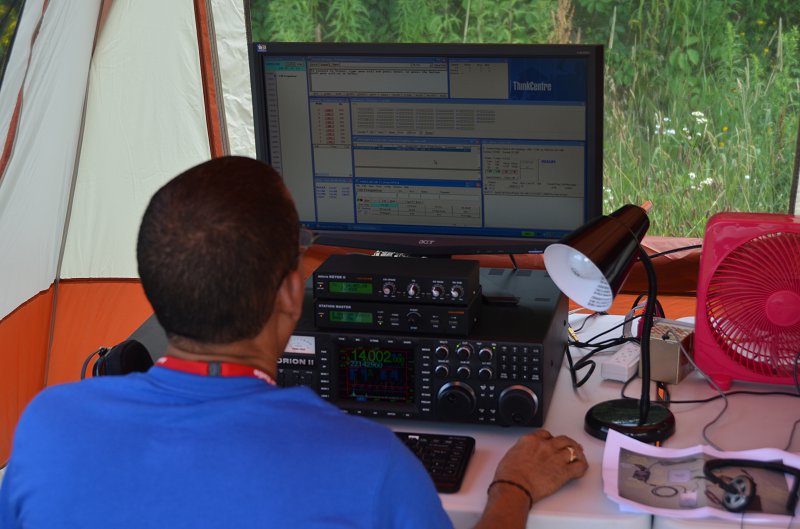
Mike Rush, KU1V Working On Our DXCC In The Contest
Mike Rush, KU1V Operating In The Contest

Everyone involved had a lot of fun and learned some new skills. We are thinking about operating again as N1FD in the ARRL Sweepstakes Contest in November (Nov. 19-21). Please let us know if you’d be interested in joining the N1FD Team for this contest.

73,

Anita, AB1QB and Fred, AB1OC

Why Would I Want To Be In A Contest?

As I sit here watching the N1FD teamwork the CQ Worldwide DX contest, it got me thinking about what contesting is really about and why we contest.

Let me try to answer the second question first. There are lots of different reasons to operate in contests. Many folks do this to work new countries, states, zones, islands, grids, etc. It seems that you can find a contest that is designed to create opportunities to work just about anything that you can think of on the bands. Others work contests to try to test out their stations and to improve their skills as operators. Of course, many folks compete to win the contest or to place better than they did the last time. Some may even compete to set a record.

Joe KB1RLC in the CQ Worldwide DX Ham Radio Contest
Joe KB1RLC in CQ Worldwide DX at AB1OC

Perhaps the best reason to contest is that it provides one of the best opportunities to be a better operator. You may say, aren’t contesters just QRM on the bands on weekends when we want to use them for other stuff? I can see why some feel this way. I wish that more amateurs who feel this way would take some time to listen more closely to what is going on during the contest.

There is nothing quite like listening to a skilled operator work a pileup from a rare place during a worldwide contest like CQ Worldwide DX. Such an operator will make 100’s of calls in a row. They will accurately get each caller’s information into their logs and the really great ones will also use their skills and energy to ensure that each of their callers gets the contest station’s information correct in their logs as well.

This requires great skill in many areas. First, you need to really learn to listen and to pick out weak and fading callers in the presence of a great deal of QRM. It’s often necessary to piece together a good callsign using several rounds of a QSO. Good contest operators know perhaps 500 or more of the most common calls used in their contest and this information helps them to recognize calls and avoid making errors. The great ones also know how to work with each caller to ensure that they get the correct information to complete the contact and that the other operator does the same.

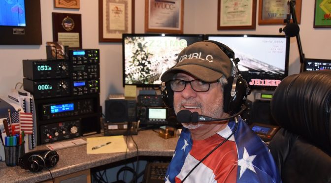
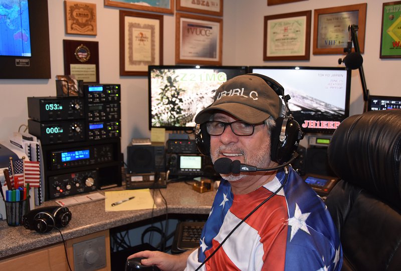
Jamey, KC1ENX Operating in the CW Worldwide DX SSB Ham Radio Contest
Jamey, KC1ENX Operating in CW Worldwide DX SSB

I like to think of this as getting in the head of the other person during the QSO.  Did they get my call right or do I need to slow down and say my call again? Did I hear their callsign and exchange correctly or do I need to give them a chance to ask me to correct something for them? While I am doing all of this, I need to be as fast and efficient as possible. These skills take a great deal of practice to develop. You can get there with less time in the chair during contests if you take some time to listen and pay close attention to the great operators that you will hear during contests. First and foremost, great contesters are great listeners and they can accurately pick out call signs on the first try without making mistakes.

N1MM+ Logger Setup For Our Contest Operation
N1MM+ Logger Setup For CQ WW DX

What, you say that any operator will do great when they are sitting at a big contest station with a lot of power and big antennas? It is true that having a well-built station and good hardware and computers helps make contacts easier. Computers and modern software like N1MM+ also play an important role in making the mechanics of finding and making contacts accurately more efficient. The contest community makes their software available free of charge to everyone. I strongly encourage anyone who contests to set up and learn to use modern contest software. While these tools help, they are just like construction tools in the hands of a carpenter. The master carpenter can create a work of art with a hand saw, a hammer and some basic hand tools while an apprentice can struggle to get good results from the best shop and tools available.

Also, most contests are designed with categories to group contesters with their peers who have setups similar to theirs. Station hardware differences also do not account for the contester who goes to an island in the Caribbean with a 100W radio and a simple antenna and wins an award in a contest.

Julio, HI3A Competing in the WRTC Ham Radio Contest
Julio, HI3A Competing in WRTC

We also saw this clearly during the WRTC competition here in New England a few years ago. We had the best operators in the world competing using the exact same towers and similar antennas that we use for our annual Field Day operation and they made 2,000 or more contacts in a 24 hour period using 100W radios. Many of these operators did this while making almost no mistakes!

So what else makes a great contest operator besides working fast and efficiently to complete and log lots of contacts accurately? For one, these folks know a great deal about propagation and how to take the best advantage of the conditions at hand. They know when it’s time to run on 20m into Europe, when to look for Japan on 15m for those multiples, what time of day and segment in the contest to focus on contacts in the Caribbean and South America, etc. They learn when they need to change bands and when it’s time to work multipliers or tune the band that they are on with their second radio or VFO. They can quickly determine the band and propagation conditions on the contest weekend and adjust their strategy to take the best advantage of the conditions at hand.

A great operator also learns to make the best use of their station and antennas. They understand where their stations work well and they adapt their approach to a contest based upon this. They also spend lots of time looking at and comparing their performance from contest to contest and against other competitors in the same contests to see where they can improve.

So what if you don’t really want to win contests? Why would you bother with this? The most important reason is that contesting will make you a better operator. You’ll learn to hear that really weak DX and get them into your log accurately. When you get on the air, you’ll be an operator that others want to work because they know you will help them complete a contact that they want. You will find and work stations that most others will miss. In short, a bit of dedication to contesting will make you a great operator.

Bands and Modes Worked By N1FD (Noon On Sunday)

As the CQ Worldwide DX Contest weekend draws to a close, I’d also like to add that I am proud of the job that the operators in our club did at our station. Most of them had almost no DX contest experience before this weekend. They worked the contest hard and have made contacts to over 100 counties in about 40 hours of operating. They have all improved their skills greatly and I look forward to working all of them at any time.

73, and see you in the contest!

Fred, AB1OC