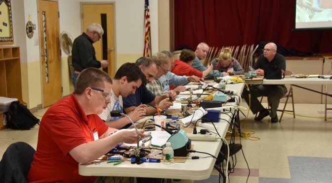
Connor (KC1GGX) and myself (Abby-AB1BY) both participated in the club’s November Tech Night. Our mission for the night was to build a 40m QRP CW Pixie Kit. Going in I was nervous – I had never soldered before – and wasn’t sure if I would understand how to put it together. Connor had done some soldering and was feeling more confident.
When we walked into the room Brian (AB1ZO) had all the kits neatly set out for everyone so we could get right to work. We opened the kits and instructions and I was overwhelmed! Thankfully we had some very experienced Elmers to help us out. Bill (K1TWO) and Charlie (AB1ZN) were extremely helpful in improving our soldering techniques and figuring out what went where. At first, I was very slow and asked a lot of questions, but as the night went on I think my technique got better and things went faster.
We worked the whole time and were the last two to finish, but when it came time to test our kits out they both worked! I was very proud of myself and learned a lot. Connor also had a great time and wants to do another project with soldering!
We would like to thank Brian and everyone involved for putting this fun tech night together.
I came across a DSO138 DIY Digital Oscilloscope Kit (SMD Soldered Version) on the Internet recently that looked like a fun project for the kids and me to work on together. The price didn’t seem bad at $24 w/free shipping. I ordered the optional clear acrylic case to go with it for another $7.50 more.
Basic specs (from the supplier site):
Maximum real-time sampling rate: 1Msps
Accuracy: 12Bit
Sampling buffer depth: 1024 bytes
Analog bandwidth: 0 – 200KHz
Vertical Sensitivity: 10mV / Div – 5V / Div (1-2-5 progressive manner)
Adjustable vertical displacement, and with instructions
Can freeze at any time waveform display (HOLD function)
Comes with a 1Hz /3.3V square wave test signal source
It came in the mail this weekend. In the box was the case kit, bag of parts, main board, display board, test cable, assembly checklist, and a basic how to use guide:
I plan to post updates on the build experience with photos along the way. Stay tuned!
We use cookies to ensure that we give you the best experience on our website. If you continue to use this site we will assume that you are happy with it.
 Connor (KC1GGX) and myself (Abby-AB1BY) both participated in the club’s November Tech Night. Our mission for the night was to build a 40m QRP CW Pixie Kit. Going in I was nervous – I had never soldered before – and wasn’t sure if I would understand how to put it together. Connor had done some soldering and was feeling more confident.
 We worked the whole time and were the last two to finish, but when it came time to test our kits out they both worked! I was very proud of myself and learned a lot. Connor also had a great time and wants to do another project with soldering!


