Tag Archives: Homebrew

The RockMite Part 3: The Oscillator

In the first RockMite article, I described the receiver of the radio. I identified the place in the receiver that accepted the output of the oscillator (marked B going into pin 6 of the mixer) but skipped describing the actual oscillator. In this article, we’ll examine the oscillator and how it drives both the receiver and the transmitter.

The RockMite Overall

As a reminder, here is the whole schematic for the RockMite.

Schematic for the RockMite transceiver (from QRPMe.com)

Figure 1. The Schematic for the RockMite Transceiver

The part of the schematic we need to analyze for this article is near the word “Transmitter” in the big schematic. I’ve cut it down in the next figure (and removed some of the distracting elements).

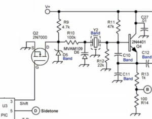
Figure 2. The RockMite Oscillator

Colpitts Oscillator

The RockMite has within it a Colpitts oscillator. The transistor Q4 is the amplifier and the two capacitors C10 and C11 form the voltage divider. This design employs a crystal (Y2) that is band-dependent, of course, as are C10, C11, and C12. The output of C12 leads to another layer of transistor amplification that enlarges the voltage swing.

Note point B between R13 and R14. This signal leads to the input of the mixer U1 and serves as the beat frequency oscillator (BFO) that detects the received signal.

Silicon Tuning Diodes

Before I can describe the rest of the circuit I need to introduce a part that I thought was almost magical when I learned about it. The part number for these devices is MVAM109 (in the center of Figure 2). The symbol looks like a cross between a diode and a capacitor. Indeed this is exactly what this part is: a diode and a capacitor combined in a very special way. The varactor (tuning) diode acts like a capacitor, but the capacitance depends on the reverse voltage across the diode. I’ve included a plot from the Motorola data sheet below.

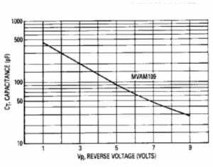
Figure 3. Capacitance versus reverse voltage

You can see that as the reverse voltage goes up the capacitance exhibited by the part goes down. Change the voltage and you change the capacitance. We use this in the part of the circuit described in the next section.

Tuning One of Two Frequencies

The oscillator uses Y2 (a crystal) to help determine the frequency. But, the frequency can be altered by adding or subtracting capacitance. MVAM109 (D6) will be the device that changes the capacitance.

Examine the circuit beginning with Q2 (2N7000). When the transistor is turned on there is a completed circuit between the source and drain (S and D in the diagram). In this case, the source is connected to ground. So, when the transistor is turned on the point in the circuit after D is brought down to zero volts.

Check out R9, a 4.7K Ohm resistor that connects to the drain of Q2, and to a Zener diode D5 (which is also band dependent, as it turns out). The Zener is used as a voltage regulator. Say the Zener is a 3.9-volt model. Since we are connected (through R9) to V+, the voltage at the point where D5 connects to R9 will be limited to 3.9 volts (or whatever the Zener is rated) and R9 is the current limiting resistor. This is assuming the transistor switch Q2 is open (not conducting).

In this situation we have D6 being reverse-biased to the voltage determined by the Zener diode. That much reverse bias will cause the varactor to exhibit some amount of capacitance.

If the switch Q2 is closed (and it conducts) then that point in the circuit is brought down to zero volts and the varactor is no longer reverse biased (or to a voltage below what the D5 part would supply) and we get a completely different capacitance.

The gate of Q2 is controlled by the UI PIC from a line called “Shift”, and it is used to switch between these two frequencies (by turning Q2 on or off). This is how the RockMite offers two different crystal-controlled frequencies with the push of a button.

Next Time

We have already gone through three-quarters of the schematic of the RockMite. Next time, in the last installment, I will walk through the transmitter and the filtering used by the radio.

Links

The RockMite Part 1: The Receiver

The RockMite Part 2: The UI

Scott, NE1RD

The RockMite Part 2: The UI

In the first RockMite article, I described the receiver of the radio. This article will describe the user interface for the RockMite. The term “user interface” might sound a little fanciful for a radio with almost no controls, but there is plenty to discuss. We should begin with the portion of the schematic dedicated to this function.

RockMite CPU and I/O
A portion of the schematic for the CPU and I/O functions

At the center of the schematic is a PIC processor from MicroChip corporation. These are small 8-bit computers that have dedicated I/O onboard. They are simple to program and are very inexpensive, key features for a radio that must cost under $50. Two of the input lines for the processor (pins 6 and 7) go to a 3.5mm stereo connector for iambic paddle input. Pin 6 connects to the “dash” or “dah” line, and pin 7 connected to the “dot” or “dit” line of the paddle. One of the functions of this PIC microprocessor is to provide the radio with an iambic keyer function.

The other user input is a single button. This button serves multiple purposes. A press of less than a quarter second tells the processor to “shift” the radio’s frequency. More on this in a bit. A longer press (greater than a quarter second) puts the keyer into “speed adjustment mode” that monitors the paddle inputs. Tapping or holding the “dit” side increases keyer speed; tapping or holding the “dah” side decreases keyer speed. Do neither for a second-and-a-half and the processor reverts back to standard iambic keyer mode.

The “shift” mode is the more interesting effects from a button press. The RockMite is actually able to operate on TWO frequencies, not just one. There is a special circuit in with the crystal controlled oscillator that causes this frequency shift. That will be discussed in the next RockMite article. All we need to know for now is that the “shift” line comes out of pin 3 and controls a 2N7000 transistor switch.

The other two outputs of the microprocessor are to the sidetone and the transmit/receive (T/R) switch. The sidetone is the sound you hear when keying. That’s the audio feedback on your paddle operation. The RockMite sends a square wave from this pin to the audio amplifier described in last month’s article. The sound of a square wave in your ears is harsh, and there are a number of mods available to clean this up.

The T/R line controls the mode of the radio. Is it in receive mode or transmit mode? This will be discussed in the article that deals with the transmitter. 

This was a brief article but we’re left with two interesting threads to pull on: radio’s oscillator (and shift function), and the radio’s transmitter (and the T/R switch). We’ll start with the oscillator next time.

Scott, NE1RD

Portable Solar Power Box

This Christmas I bought a 28 watt solar panel and MPPT charge controller from Bioenno. I haven’t had much time to use it until recently with the weather getting warmer. I’ve been able to use this with my 7.5 amp hour battery which will power the KX2 for quite some time. I’ve also been watching a lot of videos on YouTube about portable power boxes and I thought it would be nice to have something a little heftier for car camping or portable activations that I wasn’t carry gear very far.

This past week I finally got to work on it. I started with a HyperTough 19 inch tool box from WalMart for the battery box. I have two 12-volt, 35 amp hour AGM batteries from Harbor Freight that fit in the box nicely with a little extra room so that everything can be inside the box.

WalMart Tool Box to be used as the battery box

I wired the two batteries in parallel to give me 12-volts and 70 amp hours. I read that the AMG batteries do not emit any hydrogen gas so I did not put any vents in the box (yet).

12 Volt, 35 Amp Hour Batteries wired in parallel (12 volts, 70 Amp Hour)

Once the batteries were wired in parallel they fit perfectly in the box! I originally had planned on putting a small computer fan on one end to use as an exhaust and put in venting holes as well, but did not do this after reading more about the AGM batteries.

The batteries fit nicely in the box!

I took ideas from a bunch of different YouTube videos that I watched to try to fit what I wanted for the box. I started laying out where I wanted everything on the box and started drilling holes.

Laying out components

The components I have on the box are a volt meter in the center of the lid along with a master switch for power and a 2 port power pole outlet to plug in a radio. On the front side of the box I have two small switched LED lights, a port with two 2.1 amp USB chargers and a cigarette lighter adapter. All of the power runs through a fuse box. I used Velcro to attach the fuse box to the inside of the lid of the box.

Fuse Box
Fuse Box Attached

Once all the components were drilled and put in place I put the Bioenno Solar Charge Contoller in the box. I attached this with Velcro to the battery so that I can easily remove it when I want to go out for lighter portable activations.

Solar Charge Controller

The hardest part was the wiring and it wasn’t really hard, just a little time consuming. I linked all the negatives together with spade connectors and wired all the positives to the fuse box. The power pole connection was probably the most difficult.

Power Pole Connection

With the wiring complete I quickly tidied it up and tested out all the components and… it worked! I’m very happy with how it came out and can’t wait to get out and do  POTA now! Something that’s not showing is the input for the solar charge panel. I’ve got a power pole connector that will attach the solar panel to the solar charge controller. I’d like to get another connector to run through the box. As it is now I have to open the lid to charge the battery. I’m also thinking about adding a strip of LEDs around the edge of the lid for some additional light at night.

Battery Box Completed

Let me know what you think. Any suggestions as to how to make this better are also welcomed!

Front of Batter Box with switched power
Battery Box with LEDs

Jamey, AC1DC

Radio Amateurs Developing Skills Worldwide