
Recently, a magnetic loop antenna was fabricated for use by my brother, Allen, W2GYD, in his NYC apartment. The smallest dimension of his apartment window is 24″, and that sets an upper limit on the loop diameter. The direction of maximum directivity lies in the plane of the loop. There will be deep nulls perpendicular to the plane of the loop.
A diameter of 23″ is just right for standard coax lengths of 6′, 12′, and 18′. The coax is supplied by DX Engineering, type 400MAX[1]. The 6′ length works well for 1-turn, Figure 1, while the 12′ and 18′ lengths were coiled into 2-turn, Figure 2, and 3-turn, Figure 3, loops, respectively.

Figure 1. Single Loop, 6′ (183 cm) Configuration
Figure 2. Double Loop, 12′ (366 cm) Configuration
Figure 3. Triple Loop, 18′ (548.6 cm) Configuration
Pipe clips[2] were acquired from a plumbing supplier in the U.K., as 10mm plumbing supplies are readily available, and 10mm is a good match for the 0.32″ O.D. of the 400MAX coaxial cable. Pipe clips are employed to maintain the shape of the loops and to fasten the loops to the oak frame. The frame was constructed from red oak hardwood flooring. This serves as a stable measurement fixture for the loops.
A shielded coupling loop, Figure 4, was constructed from RG-8X, also supplied by DX Engineering[3]. The coupling loop is 14.4″ (36.6 cm) long, and it provides good coupling performance. The total length is a combination of interconnects within the Coupling Loop Assembly, Figure 5, the adapters, and an external 12″ length of RG-8X coax. The Bud Industries housing is PN-1331-MB[4].
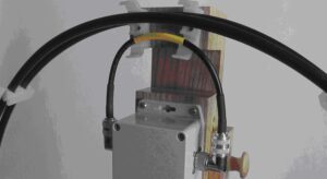
Figure 4. Coupling Loop. The position of the loop is vertically adjustable using the sliding block and pegs.
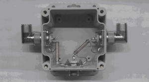
Figure 5. Interior View of Coupling Loop Box. Only the outer shield carries RF.
The capacitor, Figure 6, in the Main Loop Tuning Assembly is an M73-type that was custom manufactured by Oren Elliott Products[5].
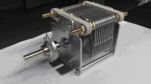
Figure 6. Custom-Made Oren Elliott Capacitor with Reduction Drive
The Bud Industries housing is PN-1333-MB[6]. As installed in the Main Loop Tuning Assembly, Figure 7, the minimum capacitance is 16 pf, while the maximum capacitance is 428 pf. This provides adequate range to tune the 1, 2, and 3-turn loops over a very large range from 80m through 12m. The minimum capacitance prevents tuning of the 1-turn loop to 10m, and a coax shorter than 6′ is required.
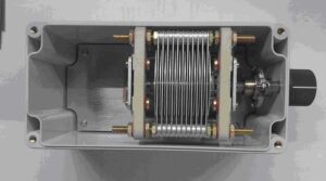
Figure 7. Oren Elliot Capacitor in a Bud Industries Enclosure. The reduction drive and tuning knob are visible to the right. An insulated tuning shaft protects the operator from high voltage.
Some adjustment of the position of the coupling loop is highly desirable. This has been verified by direct measurement of all loops on some or all bands from 80m to 12m. A sliding block arrangement, Figure 8, provides adjustment of the coupling loop vertical position with respect to the main loop. The holes in the sliding block and channel were drilled with a doweling jig[7]. Without this device, it is very difficult to drill a series of holes in a straight line. The sliding block is fixed in the desired vertical position with dowel pegs.
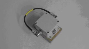
Figure 8. Sliding Block Assembly with Coupling Loop. Holes bored in the sliding block provide adjustment.
The magnetic loop is coarsely tuned to resonance on receiver noise. Fine-tuning is performed with an antenna analyzer. A Diamond Antenna CX210A SPDT switch[8] switches the antenna between a QRP radio and the antenna analyzer. The switch provides 70 dB of isolation. This is adequate to protect the antenna analyzer from QRP transmitter power. This setup works well, and there is no need to connect and disconnect coax to provide precise tuning.
Oren Elliott Products also provides a 6:1 friction reduction drive[9] so that 3-turns are required to tune from minimum to maximum capacitance. The reduction drive is essential for fine-tuning.
Interconnects within the Main Loop Tuning Assembly Figure 9, marked High Voltage, are made between the connectors and the capacitor with a 1″ wide x 0.012″ thick copper ribbon supplied by Georgia Copper[10]. This material turned out to be very easy to handle. Thicker materials, 0.016″ and 0.022″, were difficult to pattern and install. Consequently, these thicknesses were abandoned. The 0.012″ material was clamped between two thin sheets of craft plywood obtained at Michaels[11]. The plywood makes it possible to drill the 0.625″ holes for the SO-239 connectors in the ribbon. Patterning was accomplished by drilling with successively larger drill bits until a diameter of 0.625″ was achieved. Without the plywood to constrain the ribbon the drill grabs and tears the copper, even when cutting oil and a low cutting speed is employed. More than one attempt was required, as it was not possible to grind the drill cutting edges for use on copper. Metal stamping or boring would be better for creating the connector pattern in copper ribbon.

Figure 9. Tuning Assembly Mounted on the Antenna Frame
Another view of the Main Loop Tuning Assembly is provided in Figure 10. The 10mm plumbing clips are visible and serve to space the turns. A roll of copper ribbon used to connect the tuning capacitor to the connectors on top of the Main Loop Tuning Assembly is visible in the upper right of the photo.
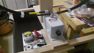
Figure 10. Frame and Tuning Assembly Under Construction
The sharp tuning null for the 3-turn loop on 40m is shown in Figure 11. For the 3-turn loop at a frequency of 7.093 MHz, the -3 dB bandwidth of the loop is 19 kHz for a Q of 373. The efficiency of the loop is 7.9% which may be expressed as -11.0 dB. Since the directivity is 1.8 dB, the resulting gain is -9.2 dB. On the higher bands, the efficiency improves.
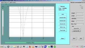
Figure 11. Sharp Tuning Null of 3-Turn Loop on 40m
Martin, K1FQL
Magnetic Loop Antenna Related References
[1] https://www.dxengineering.com/search/part-type/coaxial-cable-assemblies
[2] https://www.toolstation.com/talon-hinged-clip/p90494
[5] https://www.orenelliottproducts.com/product-category/air-variable-capacitors/m73-m90-m97/
[7] https://www.rockler.com/dowel-pro-jig?country=US&sid=V91040&promo=shopping&utm_source=google&utm_medium=cpc&utm_term=&utm_content=&utm_campaign=PL&gclid=CjwKCAjwrqqSBhBbEiwAlQeqGtcSEMJ9SNtgzGkl_7dxBONE-E3BjhOV-tR2Y5lS9HaNICw6kOyUOxoCvLsQAvD_BwE
[8] https://www.diamondantenna.net/cx210a.html
[9] https://www.orenelliottproducts.com/product-category/planetary-reduction-drives/
[10] https://gacopper.com/strap.html
[11] https://www.michaels.com/midwest-plywood-economy-bag-12ct/D508855S.html