Tag Archives: Homebrew

First Homebrew Contact on my Scratch Built BitX20 SSB Transceiver

About a year ago I decided to build an SSB transceiver for making contacts with other amateur radio operators on the HF bands.  I was given good advice from both Bill and Pete from the SolderSmoke Podcast to start out with a direct conversion receiver then go with the BitX20 as a first SSB rig.  I am very happy that they gave me that advice and I would agree that the BitX is not a good first project.

After getting all the proper adjustments made and confirming proper operation with a dummy load it was time to put this rig on the air (I don’t need a case)!   I tried calling CQ using SSB voice but no one came back.  I then decided to add some relays and other modifications to allow digital modes.

On January 15, 2017, at 21:46z I answered a psk31 CQ from Josh K1JOG in Kissimmee, FL.  Little did he know that he would be making history (maybe just for me) in my first home brew QSO.  Below is his eQSL card to me.

BitX20 First Contact QSL
Thank you, Josh K1JOG for the contact!

If you are interested in scratch building this rig you can follow the photo link  below:

BitX20 Homebrewed Transceiver
BitX by Ashhar Farhan, VU2ESE

Ashhar Farhan also sells a BitX40 at http://www.hfsigs.com/

The units he has built in India are almost ready to put on the air.  You build the case/box or just go open board style!  You can’t beat the $59 price for a rig!

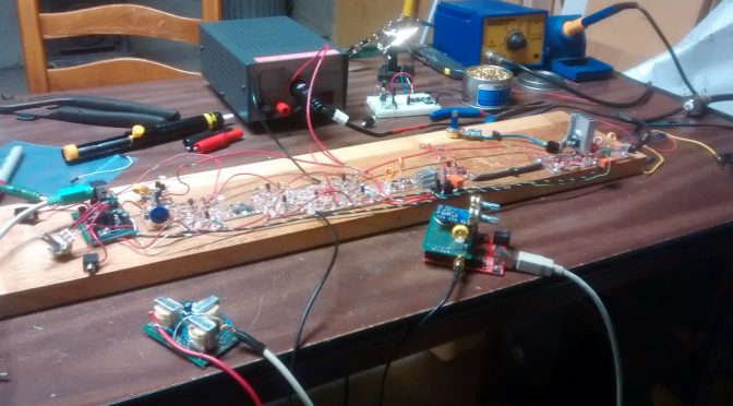
Below are some photos of my project:

BitX20 Mic amp on the left LM386 audio amp on the right
Mic amp on the left LM386 audio amp on the right

A good place to start is the Audio “end”.  I built mine using perf prototype board.  FYI the 10k ohm resistor on the mic amp needs to be 39k ohm for proper bias.

BitX20 Balanced Modulator
Balanced Modulator

On the balanced modulator, I used a mystery toroid core because I have a bunch of them and they did not cost much!

BitX 10 MHz crystal filter
10 MHz crystal filter

In this photo, you can see some transmit and receive amplifiers and the crystal filter.  I built some test equipment and used a frequency counter to make a matched set of crystals.

BitX20 Mixer circuit
Mixer circuit

The mixer circuit is shown here with some coax to the left that is from the VFO.

BitX20 VFO
Original VFO design on the left. Filtered SI5351 clock generator on the right

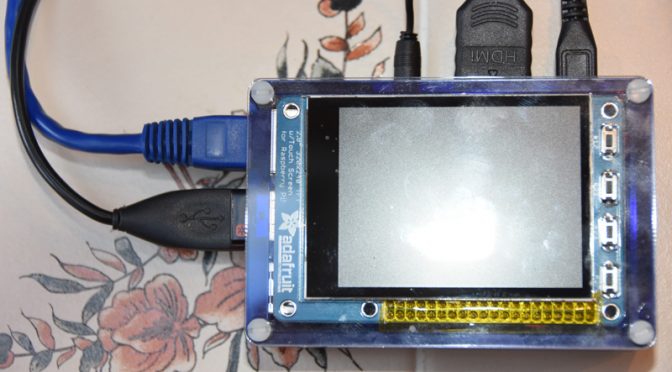
You can see the benefit of building small modules.  With SMA connectors, I can quickly swap out the VFO “soul” of this rig!  No more drift with the SI5351 chip! I ordered mine from Adafruit. I added a small LC filter to the output to make a nice sine wave.  I am not sure it is needed.

BitX20 Bandpass Filter
Band Pass Filter by Pete N6QW

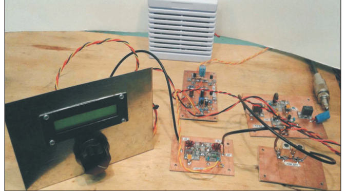
Now I had trouble with the original band pass filter.  I’m not sure why but a quick google search on 20m band pass filter and I found a replacement circuit on his website.  When I told Pete about this he sent me a new updated design to try.  My PTT relays are 5v so the small heatsink is for the voltage regulator.  I also included diode protection for the replays.

BitX20 Power Amplifier
Irf510 power amplifier

The IRF510 is more of a switch and not designed for linear RF amplification but it is cheap and works great for QRP.  They have different bias requirements from one unit to the next.  That is why you carefully set the bias level with a trim pot.  The large heat sink was part of an old high power LED driver that died.  I used T37-6 toroid cores for the low pass filter on the right. The 2nd relay was needed to prevent the output of the IRF510 feeding back into the original PTT switch and back into a nasty loop.

I am not sure if this rig will ever get a case or future modifications but I do know that I would like to see if I can make more contacts with it.

I would like to end this article with a quote I very much like from a video with Rev. George Dobbs, G3RJV

“Radio construction is rather like a pilgrimage where the journey is often more important than the destination”.

73,

Mike,  AB1YK

The DX Alarm Clock – Part 1: Raspberry Pi Software

I have been an Amateur Radio Operator for 5 years and my favorite thing to do is chase DX. As a new Ham, it was always a thrill to work a new DXCC, but now that I have over 280 DXCCs and over 1000 band points, it is a little more difficult to find a new one. Add to that the fact that I am trying to get a DXCC in 80m and 160m., which are usually open when I am asleep. I created the DX Alarm Clock as a way to get notified that there is something new on the air when I am not down in the shack.  This article will talk about how I developed the software for the DX Alarm Clock.  Part 2 will talk about building the Raspberry Pi-based Hardware and loading the OS.

DX Alarm Clock Architecture

The DX Alarm Clock is a Python software program running on a Raspberry Pi that gathers data online about my log and what is on the spotting network and uses that data to alert me when there is a “new one” on the air.

Ham Radio Raspberry Pi Project - DX Alarm Clock Architecture
DX Alarm Clock Architecture

The ClubLog website provides a light DX Cluster website called DXLite, which has an XML Interface. The DX Alarm Clock uses this interface to get the current spots. The software uses the Developer API from ClubLog to get a JSON matrix of all DXCC entities by band indicating whether I have worked, confirmed, or verified each band entity. The software loops through all of the spots returned by DXLite and looks each DXCC up in the JSON ClubLog matrix. I also use the QRZ.com XML Interface to get additional information for each callsign that is spotted, like the state.

User Interface

Ham Radio Raspberry Pi Project - DXCC Configuration Screen
DXCC Configuration Screen

The DX Alarm Clock uses Tkinter/TTK for the GUI.  I used the Notebook widget to create a multi-tab GUI.  There is a tab for configuring filters for DX Entity. The user can choose all New DXCCs, as well as specific bands and nodes to provide alerts for.

Ham Radio Raspberry Pi Project - WAS Configuration Screen
WAS Configuration Screen

There is another tab for configuring filters for WAS. ClubLog has no log look-up capability based on US State so the WAS filter lets you create a list of States and associated bands to provide alerts for.

Ham Radio Raspberry Pi Project - Notification Configuration Screen
Notification Configuration Screen

The Notification tab allows the configuration of what notifications the user would like to receive. The user can specify a separate email address for New DXCCs, New Band Points, and New US States. This allows alerts to be sent to email accounts or as SMS texts. You can also configure the sounds the DX Alarm Clock itself makes to “wake you up” when that ATNO or new Band Point is spotted.

DX Alarm Clock Alerting

The DXAlarm clock wakes up every 5 minutes and gets the latest spots from the DXLite Cluster. It checks each spot against the ClubLog log and if there is a match based on the configure filters, it sounds the alert, and then speaks the alarm, giving you the Callsign, DXCC Entity, Band, and Mode.   A simple text-to-speech package called flite (festival-lite) was used to implement the speech on the Raspberry Pi.

Ham Radio Raspberry Pi Project - Alert Screen
Alert Screen

It also puts a message with these details and the Frequency, UTC Date/Time, Spotter and Comment on the display.

Ham Radio Raspberry Pi Project - Text Notification to iPhone
Text Notification to iPhone

Additionally, it sends this information as an email to the configured email address, which results in a text or email.


Ham Radio Raspberry Pi Project - Apple Watch Alert
Apple Watch Alert

I can even get the alert on my Apple Watch.

Ham Radio Raspberry Pi Project - Filtered Spots Display
Filtered Spots Display

Once all spots are processed, it keeps a running list of all spots that resulted in alerts on the main screen. Spots are aged out if they do not recur over time.

Ham Radio Raspberry Pi Project - DX Alarm Clock Hardware
DX Alarm Clock Hardware

The DX Alarm Clock just alerted me that ZC4SB is on 20m – that’s an ATNO!  Got to go down to the shack and work him!    Stay tuned for Part 2 of this post on the DXAlarm Clock Raspberry Pi-based hardware and on setting up the Raspberry Pi OS.

Anita, AB1QB

A First Homebrewed Transceiver

I recently wrote an article about Nashua ARC’s 2017 Project Night (forgive my shameless self-promotion). In it, I expressed my awe of what our club members can do, and how it has inspired me to attempt my own first build.

The winter really is the best time to do this. And it’s time for me to embark on this journey of fun, learning, and frustration! So I turned to Mike (AB1YK) who knows about such things since he and I are attempting to organize a future summer weekend Tech Build Event for the club. The Pixie and the DSO138 oscilloscope are the warm-ups for this main-event. One suggestion Mike threw out was a Direct-Conversion Receiver (DCR) as advertised in the January 2015 issue of QRP Quarterly which you can actually download here (and as far as the application to the Tech Build goes, perhaps we only build parts of the DCR given time constraints). This article is entitled Let’s Build Something: Part I by Ben Kuo (KK6FUT) and Pete Juliano (N6QW).
Homebrewed Transceiver Block Diagram

In it, they outline the main building blocks of the build. The nice thing about this build is once one is done, it is amenable to some modular alteration to turn it into a fully working QRP SSB transceiver! (Though I do not know how much wattage at this stage) The other nice thing about this build is all the parts are clearly labeled and Pete provides links at the end of the article for YouTube videos about the build. Maybe it’s just my noob eyes, but I find the videos moderately useful for someone starting from scratch, but I can see the utility for a more experienced builder. Additionally, this build utilizes the Manhattan style of building. I find this optimal for someone just starting out because I can easily visualize all the connections between the components and have relatively easy access to make measurements and tests with probes.

Let’s go through parts and I’ll tell you what I know (at a cursory level) and what I don’t

  • 40m bandpass filter: Totally on this one. I’ve never built a filter before but looking forward to doing this. In fact, I need to build one for my ADS-B antenna at 1090 MHz, but it doesn’t seem feasible to do from components at that frequency. Any ideas anyone? I’m kind of stumped.

Homebrewed Transceiver Bandpass Filter Schematic

  • RF amplifier: REALLY looking forward to tackling this one, but this won’t be the first thing I do. Makes sense to have for weak signals.

Homebrewed Transceiver RF Amplifier Schematic

Homebrewed Transceiver RF Amplifier

  • Double-balanced mixer: Now I know something has to knock the RF down to an intermediate frequency (IF) and when I see mixer, this is where my brain goes.  The double-balanced bit was foreign to me, but as advertised in the article (‘double balanced’ implies that the original signal and local oscillator frequencies are deliberately nulled out as part of the mixing process and do not appear at the output.)

Homebrewed Transceiver Double Mixer Schematic

  • Arduino Based Sample DDS: In order to even produce an IF, we need a local oscillator (LO). This is where the Arduino comes in. The authors argued they looked at a number of options for the LO including a VFO (variable frequency oscillator), a varactor tuned oscillator (should know this from my Extra exam — but full disclosure — I can’t help you now), and a DDS (direct digital synthesizer). They felt the simplest option was the DDS (hence the Arduino).

Homebrewed Transceiver DDS Schematic

  • Audio amplifier: We want to amplify the audio signal so we can hear it through our 8 Ohm speaker!

Homebrewed Transceiver Audio Amplifier Schematic

So now if you put all the components and modules together, you arrive at something which should look like:

Homebrewed Receiver

I like this project for a few reasons.

  1. It’s a more interesting build and takes longer than 2 hours.
  2. It will have amateur radio applications in my shack. I do hope to work some pretty cool QRP with this rig (when I turn it into a full-on transceiver).
  3. I will learn A LOT about the electronic components integrated into the rig and be able to have an excuse to buy some test equipment.
  4. I get to work on my soldering skills.
  5. The modular design is attractive so that if I wish to make alterations in the future, it seems I will readily be able to do so without having to tear the entire rig apart.
  6. Understanding, at the end, how all of these parts function together to make my transceiver work. I look forward to sharing whatever knowledge I accrue during this build with future amateur radio hobbyists just breaking in.

I will certainly post articles as my progress commences. Currently, I am in the market to buy components and test equipment and will begin to build probably the simplest module first; currently, that seems to be the filter. And I have learned a very valuable lesson from being in the club and participating in its activities that I am applying to this build. Initially do things to set yourself up for the highest probability of success so that you keep your morale, interest, and momentum high. Nothing is worse than diving head-first into the hardest part of a project and losing any and all ambition when things begin to not work (and they will…).

73,

Brian, AB1ZO

Radio Amateurs Developing Skills Worldwide