Tag Archives: Homebrew

DX Alarm Clock Part 2 – Hardware

I recently wrote a blog article about the DX Alarm Clock software – here is Part 2 of the Series on the how I built the hardware for the DX Alarm Clock.

DX Alarm Clock Hardware Components

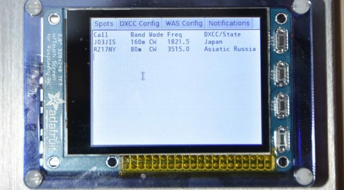
The DX Alarm Clock is based on a Raspberry Pi 3 computer and an Adafruit Pi-TFT Touch Screen Display.  The list of components, along with links is below.  Since I built the Raspberry Pi almost a year ago and technology is always advancing, some of the parts are no longer available or have better replacements available.  I’ll provide information on what I used and a recommended replacement.  Approximate prices are included.

Raspberry Pi 3
Raspberry Pi 3

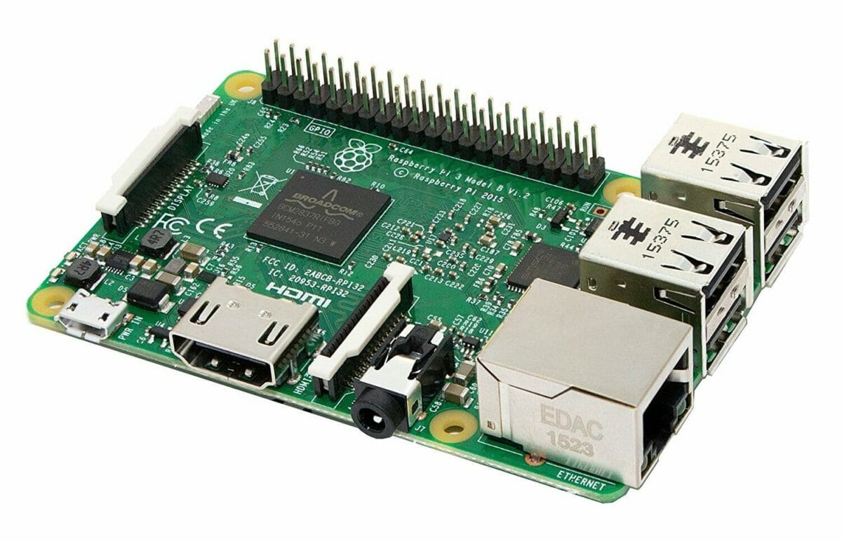
Motherboard: Raspberry Pi 3 ($35) – includes a 1.2 GHz 64-bit quad-core ARM CPU, Build in WiFi, Ethernet, 4 USB Ports, an HDMI port and audio port (3.5″) and Bluetooth.

Also, you will need a power adapter  ($10) and Class 10 Micro SD card ($15) for the Raspberry Pi.  Ours is a SanDisk Ultra 64GB Micro SD Card.

Pi-TFT Touch Screen Display

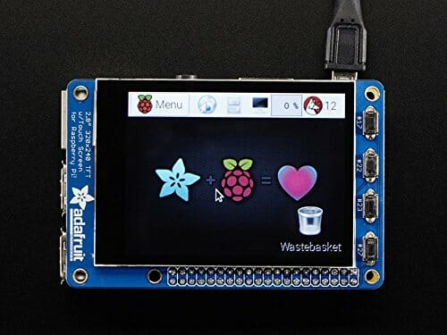
Display: Adafruit Pi-TFT 2.8″ Display with Capacitive Touch Screen ($45).  A slightly larger, 3.5″ display is now available.

PiBow Case
PiBow Case

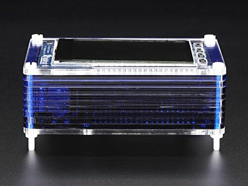
Case: Pimoroni PiBow Case for Raspberry Pi and Pi-TFT Display($20)

Kinivo Speaker
Kinivo Speaker

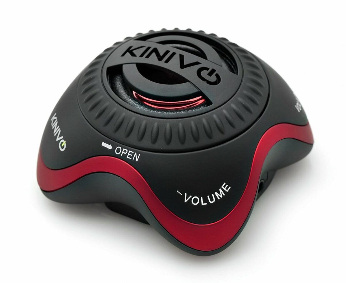
Portable Speaker:  Any small portable/rechargeable speaker will do.  Mine is a Kinivo, but it is no longer available.  Any small speaker will do as long as it is Bluetooth or has a 3.5″ stereo connector.

Completed DX Alarm Clock Hardware

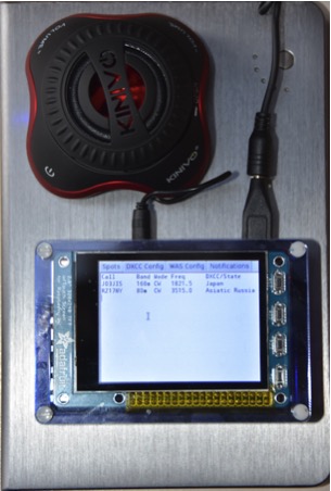
The picture above shows the completed DX Alarm Clock Hardware running portable using a USB battery pack.

Raspberry Pi Development Environment

Raspberry Pi Development Environment

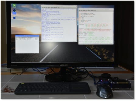
After constructing the Raspberry Pi, case and TFT Display, the next step was to connect it to a monitor via the HDMI port, a mouse via one of the USB ports and to a Bluetooth keyboard.   Then I loaded the Raspbian Operating System onto the Raspberry Pi via the micro SD card.  I first copied the OS to the Micro SD card using a PC or Mac and then inserted the card into the Raspberry Pi and booted from it.  You can find a good tutorial on how to do this at https://www.raspberrypi.org/learning/software-guide/quickstart/

Once Raspbian is installed, you will have a windows like GUI (Graphical User Interface) environment with a web browser, and a number of additional applications included.

This gave me a development environment that I could use to build and test the DX Alarm Clock software.  I used the Python language to develop the software.  I used the Python IDLE development environment, which is included in the Raspbian OS.

Interested in Raspberry Pi Amateur Radio Projects?  See the article on a Raspberry Pi Satellite Rotator Interface.

Raspberry Pi Satellite Rotator Interface

We’ve been using our Portable Satellite Station 2.0 for some time now and it works great. One area that can be improved is the interface between the MacDoppler Satellite Tracking program we use and the GHTracker application which controls the Green Heron Engineering RT-21 Az/El Rotator Controller in our setup…

Source: Raspberry Pi Satellite Rotator Interface | Our HAM Station

The Raspberry Pi is an inexpensive computer and control platform for many Ham Radio projects. We recently used a Raspberry Pi 3 to build an interface between the MacDoppler Satellite Tracking Software in our Portable Satellite Station and the Rotator Control System points the ground station antennas during satellite tracking. We put together an article about how we went about this project and some details of the hardware and software we used to put a Raspberry Pi 3 computer together for our project.

Fred, AB1OC

How did I hang my dipole 50+ feet high in the trees?

Dipole Antenna Tree

I wanted to make an article that would explain to anyone who visits my home or QTH that would answer the question on “How did you get that rope so high in the trees and how did you get that rope over the perfect branch?

I started out with a fishing pole and a 4-inch long stick from the woods.  After a few attempts of getting the stick up and over the tree with the fishing line it finally made it over the tree and back to the ground.  I then reeled in all the fishing line while pulling a string over the tree.  After the string, I used it to pull over 3/8” poly rope.

I came up with the following idea to get a rope over the perfect branch.

Dipole Antenna Tree

The 3/8″ line holds an old branch from the woods in the center. The yellow rope to the left is the “control line” and the right side has a half rotten log as a weight secured with a slip knot as shown below.

Dipole Antenna Tree

In the diagram below the light blue line represents the yellow control line from the photo.  As you lift the whole unit you should consider that the weight of the control line may offset your balance as you go higher.    The magenta line shows the string with a slip knot.  When the half rotten log made it over the desired perfect branch by combinations of pulling the 3/8″ rope at either end (shown black) and/or the control line (shown light blue) I pulled out the slip knot and the half rotten log fell over the perfect branch along with the string (shown magenta).

Dipole Antenna Tree

I replaced the string with rope and then a wire rope loop (shown red). The wire rope will not fade and fall apart from the sun’s UV rays. The yellow circle represents a pulley for the poly rope that holds up the dipole. When the poly rope breaks down from UV, wear and tear it can easily be replaced by lowering the pulley.  I added weight to maintain proper tension on the dipole antenna as shown below.

Dipole Antenna Tree

In theory, the tension will remain the same even in wind storms when the trees swing back and forth. It turns out that an old cast iron rotor from my Toyota was the perfect weight for the application!

73,

Mike AB1YK


Radio Amateurs Developing Skills Worldwide