Tag Archives: Education and Training

Daiwa CNW-419 Tuner Repair

Although I am brand new to the hobby of ham radio, I have been playing around with electronics and digital circuits for as long as I can remember. I am a software engineer by trade and have always loved the problem-solving challenges that software and hardware engineering offers.

Given my unfamiliarity with the ham radio world, however, I thought it might be fun to find a project in that space. Enter the Daiwa CNW-419 manual tuner.

Our Next Victim

My father found this poor soul on eBay, and it was in a bit of a bad way. It had some missing feet, the tuner button “didn’t work”, and there seemed to be a couple of loose pieces in the pictures, but generally the interior of the tuner looked very clean.

After looking up some reviews of the tuner and finding nothing but praise, I thought what the heck, paid the $75 and took the plunge.

It arrived carefully packaged, and after unwrapping it, I found that the tuner switch was indeed broken. In addition, the switch to change the antenna (it supports two antennas), didn’t seem to be working properly either. Both of the switches were push buttons, and neither of them would latch.

Taking It All Apart

A first look under the covers

Time to take the cover off and see what was going on. With just the top cover off, we can see the two problematic switches in the back. If we’re going to get to those switches, a lot more stuff is going to need to come off.

After removing the bottom, and disconnecting the back panel, we get a better view of the switches. Some black charring there, perhaps some RF arcing took place? Looking at the rest of the box and how neat and organized the soldering and wiring is, this looks out of place. I am beginning to suspect something is amiss here.

After pulling the switches completely out, there definitely appeared to be some sort of overload. Or perhaps just bad soldering? More investigation is clearly required.

Our problematic switches

The Game is Afoot

Examining the part number for the switches I pulled out, I was able to find the equivalent switch on DigiKey. The schematic for this switch indicated that it was simple non-latching push button ON-ON DPDT switch. Clearly not the original part, as the tuner front panel artwork indicates that these are latching push button switches.

At this point, I headed back to google to see if I could find what the original switch was, but could find nothing. Finally, I stumbled across an interior shot of the tuner from a guy in Thailand. After some zooming, it looked like an ordinary latching switch.

But First Some Math…

The tuner is rated for a maximum of two hundred watts, so we should figure out what our switches need to be able to handle. We don’t want to trust the previous components ratings since they were not original.

One hundred watts at fifty Ohms yields an RMS voltage of about seventy volts which is what my receiver puts out. Since the tuner is rated to two hundred watts our max RMS voltage should be one hundred volts. 125VAC switches are plentiful, and to be safe we should also probably shoot for a switch that can handle around five amps. Eight dollars and fifty-two cents later, we have a pair of switches rated at 125VAC and seven amps. Perfect.

Putting It All Together

I took lots of photos and notes while removing the switches but knowing that they could have possibly been installed incorrectly, I took a little extra care in laying out the connections for the new switches.

The switch for the antennas was straight forward enough. This was simply a DPDT doubled up and wired as a SPST with the center poles connecting to the center pole output of the tuning circuit switch.

The new switches installed

The switch for the tuning circuit was a little peculiar. When the tuning circuit is disengaged, the switch should connect the output from the amp making sure it passes through the metering circuit and bypasses the tuning circuit. Originally, the switch connected the first pole to the second pole of the switch using only the thin wire of a small capacitor hanging down. This was clearly insufficient, and somewhat dangerous as that thin wire would be passing the full power RF output of the amp. I suspect this probably happened at one point as the capacitor wire was extremely brittle, and broke after I removed it.

A Puzzle for Our Readers

The dangling capacitor was likely a power filter circuit (that’s my guess). You can find these on regular power circuits where a high voltage cap connects the power to ground. I assume they are also used on RF power circuits. Is this correct? Ham radio experts feel free to chime in. I tested the untuned circuit path both with and without the cap filter but could discern no difference. I suspect it might have been affecting my output signal, but I had no way to test that. In the end, I left it connected, figuring I would not do much transmitting with the tuning circuit disabled.

Tuning it Up

Time to test it out. Here it is with some new rubber feet from the hardware store ($2.47) sitting on top of my FT-450D.

The new, and the slightly less new

I purposely detuned my vertical, disabled the ATU on my receiver and checked the SWR. Infinite SWR readings for both the tuner and my receiver. Great. The auto tuner on my receiver can’t touch that. I then enabled the tuning circuit on the Daiwa, found the best band setting, and tuned it up. In no time I had the SWR down to one, and the forward power at maximum.

I love this thing.

A Block Diagram for the LNR Precision MTR3b

When I was a young child, there was nothing more dangerous in the house than me and a screwdriver. I took everything apart. Nothing was safe. I wanted—no needed—to see the insides of things, and see how they worked. At some point, learning how to put things back together was the only thing that kept me from a seriously sore backside. Still, every bit of it was worth it, and I have retained that kind of curiosity throughout my life and my career. 

Things are a little easier today. You can understand a lot from just looking at the drawings for a device. One of the things I enjoy doing is looking over radio schematics and trying to understand how they work, and the choices that the designers made. In this article, I’d like to do that for the three-band Mountain Toper MTR3b, a radio designed by Steve Weber (KD1JV) and sold by LNR Precision.

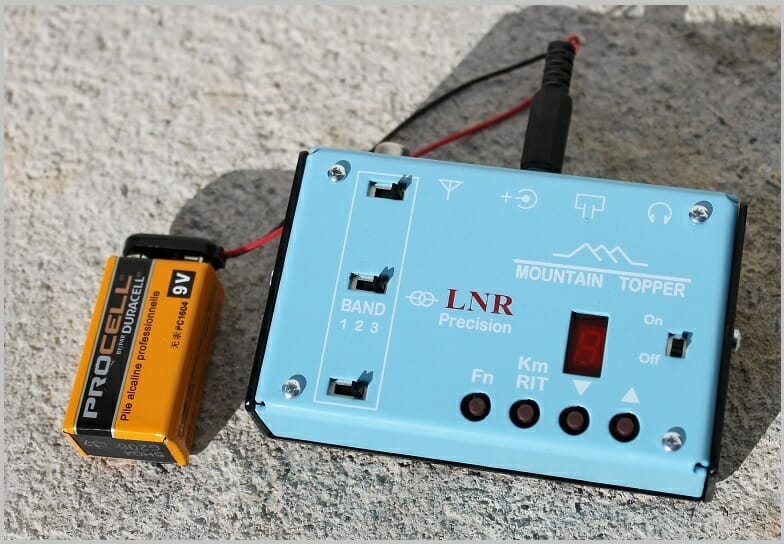
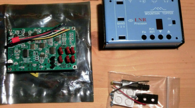
The MTR3b is a CW-only, 3-band (20/30/40) radio that can fit in the palm of your hand. The photograph of the radio with an accompanying 9-volt battery gives you some idea of its size, though you don’t truly grasp the compactness of the unit until you hold it in your hand. The 9-volt battery is not just a prop for the photograph. The radio can be powered by a single such battery, though it works better with something a little larger. I use a compact 11.1-volt LiPO battery packs made popular by drone users.

I’m not going to provide a detailed review of the user interface (just 3 slide switches, four buttons, and a single 7-segment LED), or go through its on-air performance. There have been several excellent reviews for this radio in QST and other places. Instead, I’d like to take it apart for you. Well, not exactly disassemble it as much as analyze the schematic and see how Steve Weber made it work.

I was lucky enough to have a fellow named Mr. Davis for my high school physics instructor. He said many wise things (that I only understood long after high school, alas), but one that stuck immediately was his adage, “If you can’t draw the picture, you don’t understand the problem.” How very true! So, I often made models and block diagrams of things to better understand them. These models don’t need to be exact. In the words of George Box, “All models are wrong, but some are useful.” A block diagram of the insides of a transceiver can be useful. Here’s the diagram for the MTR3b I sketched on my iPad Pro tablet a few evenings ago.

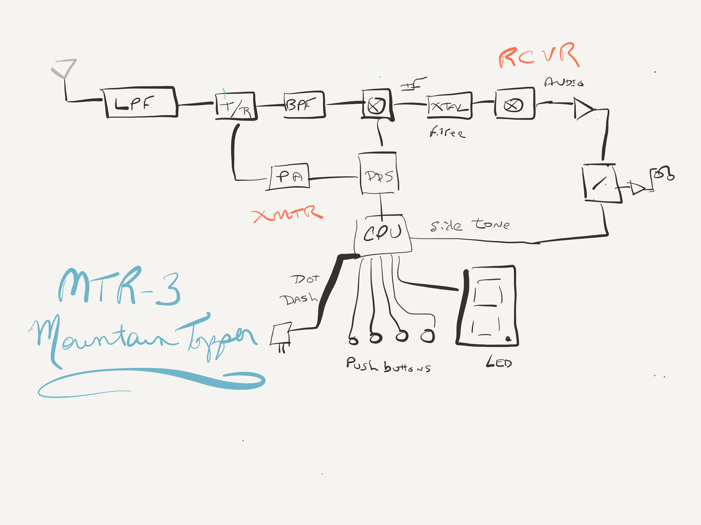
Let’s walk through it. The antenna is on the far left. The antenna connects to the radio and is presented to a low-pass filter (LPF). As it turns out, each band requires its own special LPF so there are slide switches on the front of the radio to switch-in the correct filter. Switch position 1 is for 20m, switch position 2 is for 30m, and switch position 3 is for 40m. The way the radio is designed, as we will see, it is important that all three switches be in the same relative position for the radio to operate properly. 

The next thing in line as we walk towards the receiver is a transmit-receive (T/R) switch. When we transmit, the signal path is cut off from the receiver and the transmitted signal only goes to the antenna. When we are receiving, the signal path is routed to the receiver, pictured along the top of the diagram.

After we pass the T/R we have a band-pass filter (BPF), also selected by one of the slide switches, that rejects out-of-band signals. This is the lead-in to the first mixer that generates the intermediate frequency.

We should take a quick detour for a moment and review what a “mixer” does. A mixer is an electronic device that takes two signals in and yields four signals out. It sounds complicated, but it really isn’t. Say we have two signals of frequency A and B. The mixer will output those same frequencies A and B (not very interesting), and two other signals: A-B and A+B. These signals are interesting. 

Superheterodyne receivers like this one mix the received signal with one from the radio (tied to the main tuning system) to produce an intermediate frequency that can then be further processed. By turning the original signal received from the antenna into this intermediate frequency, we can have a system common to all three bands 20m/30m/40m in the rest of the receiver. This common system works because it only has to deal with signals at this selected intermediate frequency. The intermediate frequency selected by Steve Weber for this design is about 4.1 MHz.

After we mix the signal with the first mixer (illustrated as a circle with an X in it), we pass the resulting signals through a crystal filter that allows only the 4.1 MHz-related frequencies through it. This is the A-B output from the mixer. The other products are discarded. Once through the crystal filter, we now have a nice signal from our selected frequency, but it is in the 4.1 MHz range. We need a subsequent step to bring it down to the audio frequency range.

The product detector that produces the audio frequency range signal from the 4.1 MHz intermediate frequency is obtained by passing the signal through a second mixer. When we’re through here, we have something our ears can hear. All that is left is to bring that audio signal through a few amplification stages, and send it to the headphones. This radio is so simple that it doesn’t even have a volume control! 

Just before the headphones is a multiplexor that allows audio to be selected from either the receiver (as we’ve just done above), or from the sidetone generated when we send Morse code. The CPU generates the sidetone signal and controls the multiplexor. This is the whole receiver.

The transmitter is even more simple. The Texas Instruments extremely-low-power CPU watches the paddles, slide switches, and push buttons, and controls the 7-segment LED display. When dot or dash paddles are pressed, it signals to the DDS (Direct Digital Synthesis) frequency generator to output a signal. (The DDS is also used to select the receive frequency.) The output signal is sent through a few amplification stages, the T/R switch is changed to transmit, and the amplified signal is sent to the antenna.

I was able to get all this just by perusing the schematic included at the rear of the MTR3b manual. You can download the manual for free from the LNR precision website and follow along from the block diagram I’ve provided.

Every time I do this for a radio I feel like I’ve learned something new. It is also gratifying to use a radio that you understand, and know how it works under the hood. 

http://www.lnrprecision.com

Scott, NE1RD

Extra License Class – April 27-29

The Nashua Area Radio Society will hold our final license class of the Spring 2018 season, the Amateur Extra License class, on Friday – Sunday, April 27-29.

The Extra Class License is an upgrade from General Class.  Extra class will give you access to more frequencies on the HF bands, especially where those rare DX like to operate from.

Spring 2018 Extra Class Flyer

Day 1 of the class will be held at AB1OC/AB1QB’s QTH.  We will have lots of demos to help reinforce the material including test equipment, antennas and operating.  Days 2 and 3 will be held at Dartmouth-Hitchcock.

Gordon West Extra Class Book
Gordon West Extra Class License Book

Class preparation

To prepare for the class, you need to read the Gordon West Extra Class book, which can be found on Amazon.com.  When you register, we will send you a pre-work assignment based on the materials in the book.

We also recommend that you take practice exams like those from AA9PW or HamTestOnline.

To register for the class, visit https://www.n1fd.org/amateur-radio-license-class-registration/

Any questions?  Contact Anita, AB1QB at [email protected].

Radio Amateurs Developing Skills Worldwide