Last Thursday, April 30th, 2020 was a day of firsts for the ARISS program and for us here. The COVID-19 situation has forced changes to be made in the way that schools and other groups contact astronauts onboard the ISS. The pandemic has also made it impossible to access many of the ARISS telebridge stations worldwide.
We hosted the first ARISS arranged Multi-Point Telebridge contact with students in the Northern VA School Group and Chris Cassidy, KF5KDR aboard the ISS. The contact was a success and we learned a great deal as we provided in a new format for ARISS contacts.
ARISS First #1 – We’re A New Telebridge Station
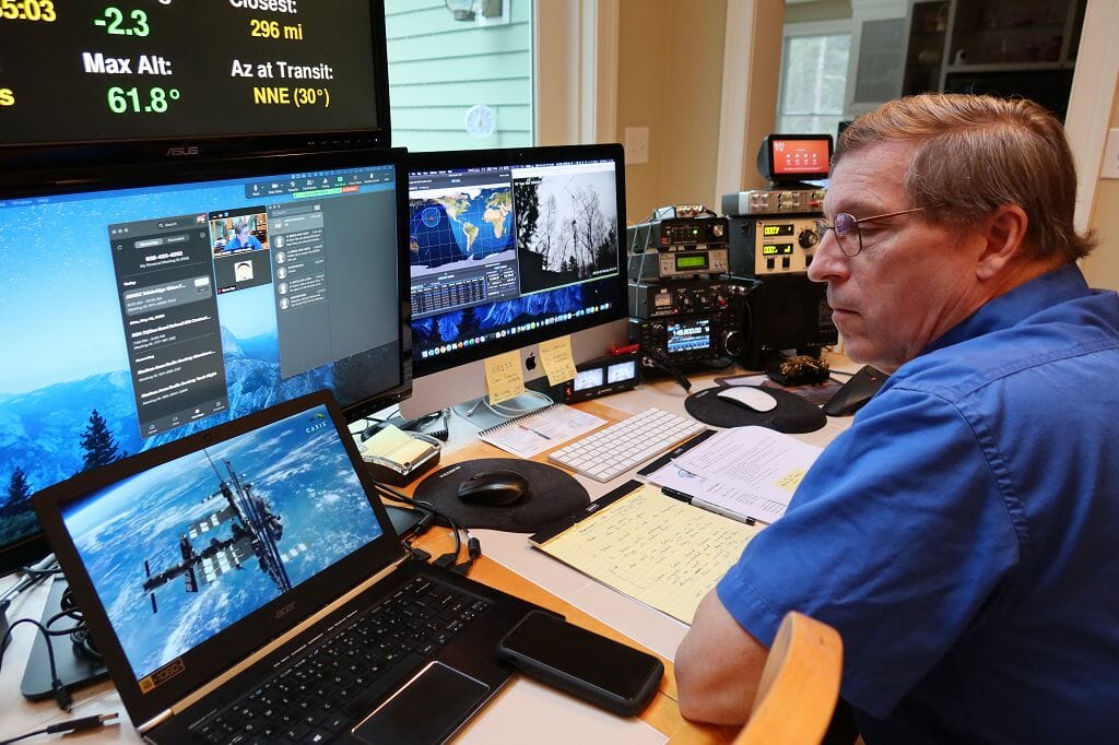
Ready for Our ISS Contact
We added Telebridge capability to our space communications ground station here in New Hampshire. This involved adding a telephone patch capability to our station and a UPS to the power supply for our station. With all of the tests complete and the station preparation checked one last time before our schedule contact, we were ready!
ARISS First #2 – New Multi-Point Telebridge Format for ARISS
The COVID-19 situation is preventing most schools from assembling in a group for their contacts with the ISS. ARISS created a new, Multi-Point Telebridge format which allows students and their teacher to participate in a contact with an astronaut aboard the ISS from their homes. The new format created additional audio and coordination challenges among the students who participated in our contact.
We practiced the new format with the students multiple times before our actual contact. As a result, the students did a great job during their contact.
ARISS First #3 – Inaugural ARISS YouTube Livestream
With the help of Steve Rys, KB1VYD, ARISS created a live, multi-sourced video feed of the pre-contact program and the actual contact with the ISS.
Pre-Contact Program (Playing on the laptop in the foreground)
The live stream included audio from our station, the Moderator for the contact (John Kludt, K4SQC), Chris on-board the ISS, the students, and Kathy Lamont, KM4TAY, their teacher.
ISS Contact Livesream to YouTube
The video portion of the program included videos that explained how the contact was arranged and works, a live video of our antennas as they tracked the ISS, the student’s questions, and a view of the ISS track as it passed overhead.
The live YouTube video stream went extremely well and was well received by over 300 viewers during our contact making it the most widely enjoyed firsts for ARISS on this day.
First #4 – Chris Cassidy’s First Contact From The ISS
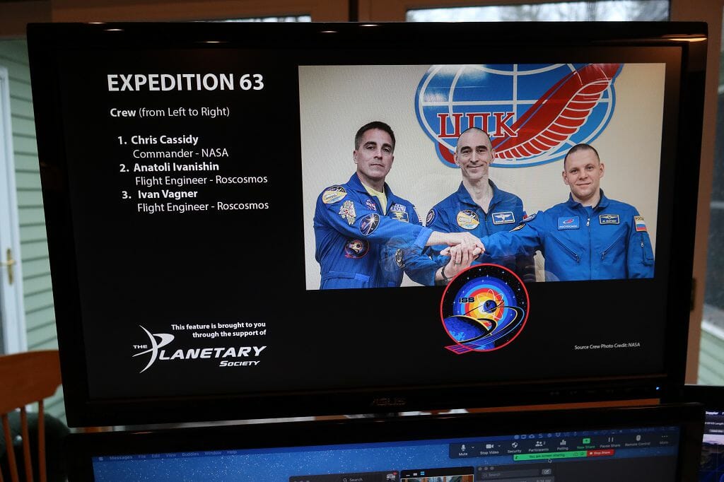
Our Astronaut, Chris Cassady, KF5KDR
The Northern VA School Group contact was Chris’ first from aboard the ISS. Chris had trained for the contact on the ground before his flight to the ISS.
Unbeknownst to Chris and the rest of us, there had been a reconfiguration of the radio equipment we would be using for our contact on the ISS. As a result of this, Chris had trouble getting the Amateur Radio for our contact going on the ISS. We did not make contact with him until some time after the ISS was over our location.
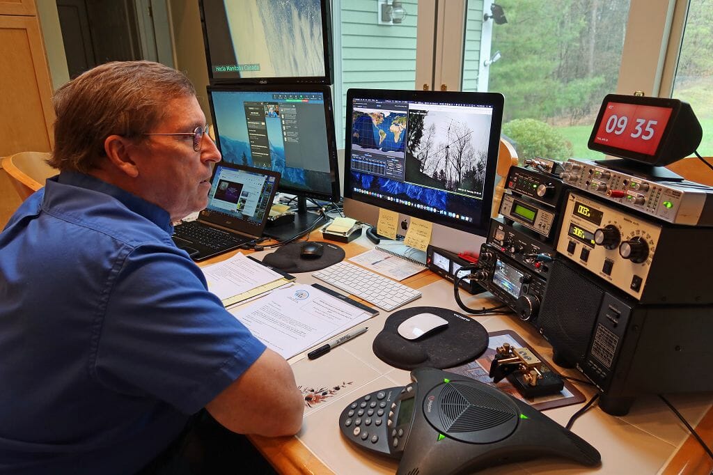
Calling the ISS for our contact
Once we got the problem sorted out, Chris came through loud and clear. He was able to answer several of the student’s questions before the ISS disappeared over the horizon.
What Comes Next
Our contact proved the effectiveness of the new ARISS Multi-point Telebridge format. It also proved-in the operation of our Telebridge Station here in New Hampshire. This was a great outcome given all of the Firsts for ARISS that were involved.
Additional Telebridge stations around the world will be hosting school contacts using the new format in the near future. We are looking forward to continuing to support the ARISS program via additional Teleridge contacts from our station.
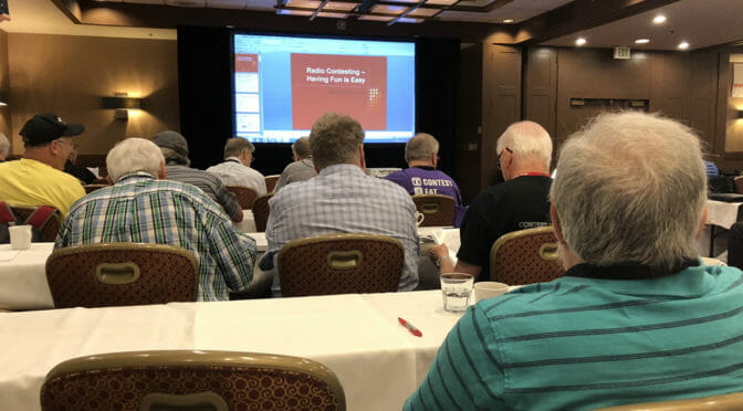
The 2020 Dayton Hamvention has been canceled, but you still have the opportunity to attend Contest University from the comfort of your QTH! The organizers of Contest University will be holding a free Virtual Contest University via Zoom on May 14th.
Contest University is a full day of educational presentations. The world’s most skilled contesters share their knowledge. You will learn not just how to operate in a contest but skills that are useful for all ham radio operators:
How to improve your station
All about propagation and when to operate to get the most and most distant contacts
Information on setting up your digital station and operating digital modes,
What are the best performing transceivers based on testing by Rob Sherwood, NC0B
And much more!
Fred, AB1OC, and I have been attending Contest University for many years and we learn something new every time. Contest University is highly recommended for our Student/Teacher Contesters as well as all of our members.
I often see debates on the various forums on where the lightning surge protector should be placed in an RF coaxial feed line from the antenna. Some say it should be at the antenna and others believe it should be at the equipment end of the coax.
The coaxial surge protector must always be near the equipment end of the coax, even when there is a DC connection between the shield and center conductor of the coax at the antenna. Examples of a DC connection at the antenna include a “gamma match” or hairpin where the shield and center conductor are DC connected, often through a large gauge conductor.
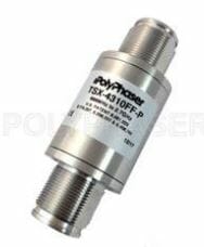
The Purpose of Surge Protectors
The purpose of the surge protector is to clamp the voltage between the coax shield and center conductor at the RF input connector on the radio to a level that will not damage the radio. For most radios, the maximum voltage with a duration of 10s of microseconds is in the range of 40V to 60V. The only way to ensure the voltage is sufficiently clamped (reduced) before entering the radio is to put the surge protector near the radio.
Surge Protectors are not effective when placed at the antenna
A surge protector or a DC connection at the antenna end of the coax is not effective. At the moment of a lightning strike on or near the antenna the voltage on the coax center conductor and the shield are equal and their voltage difference is 0V.
As the voltage spike travels down the coax two physical properties of the coax will result is a voltage difference between the coax center conductor and the shield.
The larger shield has lower inductance than the small-diameter center conductor. The spike on the center conductor will be stretched in time due to the higher inductance.
The propagation velocity on the center conductor is lower than on the shield due to the dielectric surrounding the center conductor.
The voltage spike on the shield will get to the radio before the spike on the center conductor.
The difference in pulse shape due to the inductance and the velocity due to the dielectric may result in a large difference in voltage between the radio’s RF connector shield and center pin possibly damaging the radio.
The body of the surge protector is a convenient contact point to connect the coax shield to the station ground before the coax enters the shack. If there is a short coax run between the surge protector and the radio this is adequate. If the run is much over 10m the voltage spikes will once again become offset and a second surge protector at the radio or station’s coax switch is recommended.
Surge Protector Designs
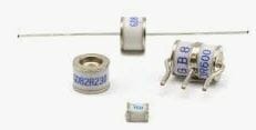
The majority of surge protectors use a Gas Discharge Tube (GDT) to clamp the voltage. GDTs in common packages are shown in Figure 1.
The pill-shaped GDT is replaceable in some surge protectors. Most GDT devices are argon filled and are hermetically sealed so their trigger and clamping -voltages are not affected by humidity or atmospheric pressure. Below the trigger voltage argon is non-conductive, as the voltage increases the argon will become conductive as it begins to plasma. Once the current exceeds the plasma state the argon will go into an arc state where the clamp voltage can be as low as 15V at 20kA. This process occurs in < 1ns. Coaxial surge protectors are rated by maximum RF power. This is based on the “flash over voltage” rating of the GDT used in the surge protector.
A surge protector with a lower power rating (e.g. MFR-270 400 watts) may flash over and clamp at a lower voltage providing increased protection to the radio. It will also flash over and clamp when used with an amplifier at >400W and damage the amplifier since it will clamp (short) the RF output of the amplifier. It is important to use a surge protector rated for the RF power expected. Surge protectors with replaceable GDTs can be upgraded for higher power by replacing the GDT with a higher flash overvoltage.
“Surge protectors” can be found on-line that use a set screw to set a spark gap. They should never be used, the gap must be set very small to provide adequate surge protection. The flash overvoltage is unknown. It will vary with humidity and atmospheric pressure. Expansion with temperature or moisture may cause them to short out which will damage a radio or amplifier.
GDTs are available from Digikey for $1.25 each. I use GDTs with axial leads between the PSU outputs and from the outputs to the PSU case/ground, from each rotator wire to ground, and on other wires in and out of the shack. It is important to select a GDT with a higher clamping voltage than the wire it is protecting.
A GDT with a 75V flash over and 12V clamping will remain clamped on a +14V line once it is triggered. GDTs are not used on 110Vac or 220Vac power lines.
The surge protector is just one component of a station’s ground system. It does the job of keeping the center pin of the radio’s RF connector at the same voltage as the shield connection and therefore the radio’s chassis. Some like to think of the station ground as “fixed” at 0 volts, it is far from it during a strike. A typical strike is 10kA and can be 100kA or greater. A typical ground rod is around 5 ohms. The voltage at a single ground rod during a typical strike is 50kV (E=IR). The surge protector has clamped the coax’s center conductor and shield to roughly the same voltage protecting the input of the radio but this “same voltage” is on the order of 50kV.
The Surge Protector and Station Ground System
If the PSU and computer are grounded using the wall plug’s safety ground which terminates on the other side of the house at the service panel’s ground, which is near 0 volts, there will be a 50kV difference between the radio’s chassis and the components and DC wires to the PSU and through the radio’s USB components to the USB cable connected to the computer and damage will occur. The surge protector must be view as part of a grounding system.
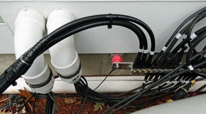
A Ground System
Once the coax surge protector, power strip surge protector, radios, PSUs, amplifiers, computer, and anything else at the operating position are all connected to the station ground and to the ground rod they will ALL raise to 50kV together and damage may be avoided. The process of ensuring everything stays at the same potential is called “bonding”. It only takes one stray path to permit considerable current to flow through the equipment. That can be an arc to a lamp on the bench plugged into a different wall circuit or to a VHF coax that bypasses the station ground.
For a small shack, implementation is not difficult or expensive. I have a piece of ¾” copper pipe across the rear of the station bench with a series of ¼” bolt holes. Each piece of equipment including the metal Belkin power strip and the computer has a short ¾” wide braid connecting it to the pipe. Every cable, coax and wire has a MOV or gas discharge tube (GDT) connecting it to the pipe before it leaves the shack. The last non-bonded wire was the CAT-6 Ethernet wire which I replaced with a wireless Wi-Fi dongle.
The pipe is connected to the station ground rod which is also connected to the service ground. I do not want the fire risk of the bench arcing to the house wiring.
Other Advantages
An already low receiver noise floor was reduced by an additional S unit or more due to the grounding.
We use cookies to ensure that we give you the best experience on our website. If you continue to use this site we will assume that you are happy with it.