We have been working with the students and faculty at Bishop Guertin H.S. (BGHS) here in Nashua, New Hampshire for several years now. This is the story of their planned contact with the International Space Station (ISS).
Amateur Radio STEM Learning Projects
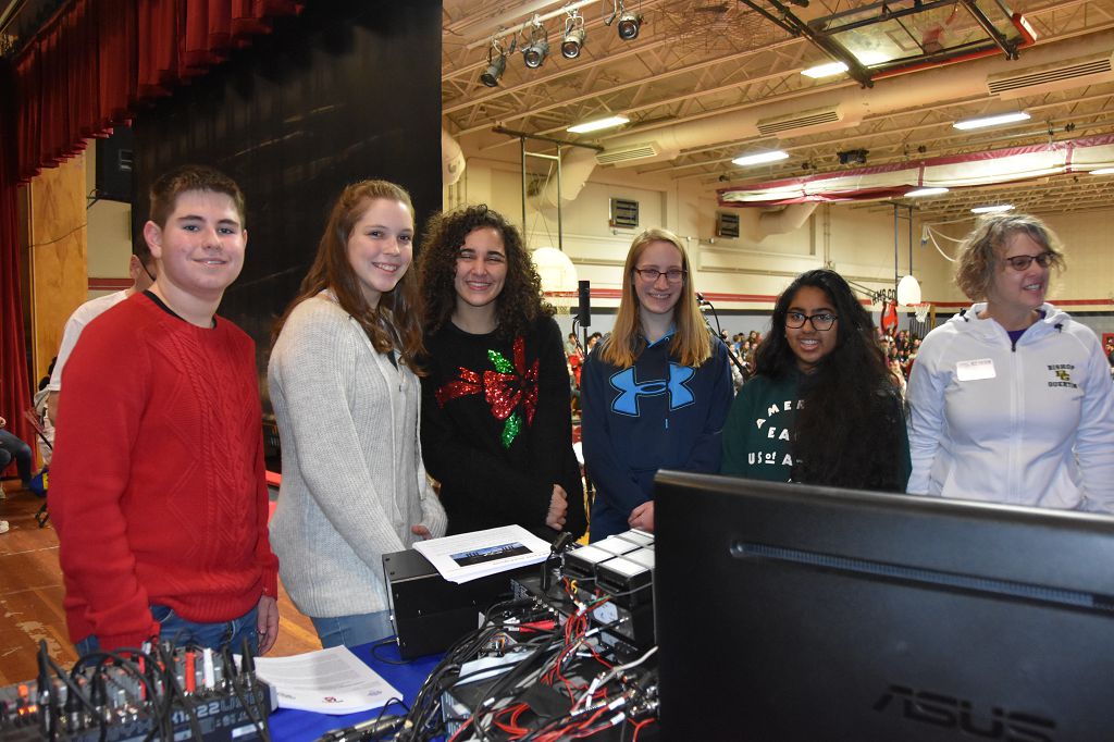
The STEM Club at BGHS has done quite a few Amateur Radio-related project with us.
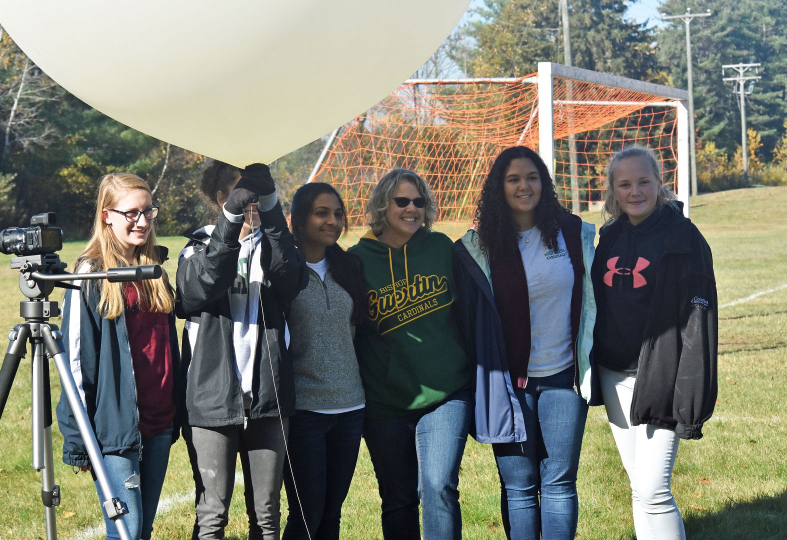
Our High-Altitude STEM Learning program got its start with the students at BGHS and they have been part of several HAB projects and launches.
The video above shows the students launching the HAB.
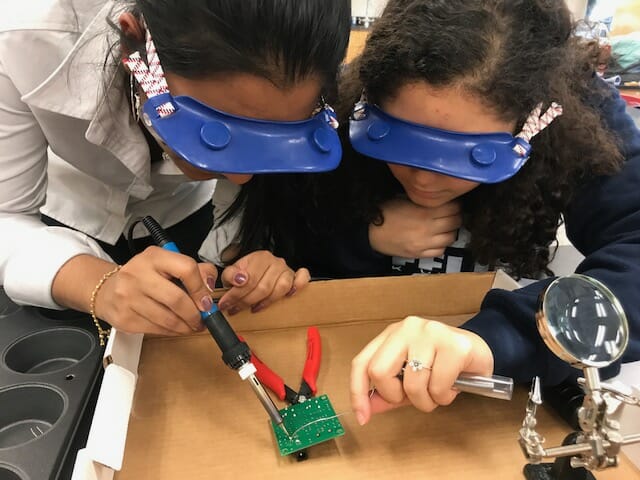
We also built CW Transceivers and Morse Code Practice kits as part of the STEM club activities and BGHS.
All of this has led to several students and their teacher becoming licensed Amateur Radio operators.
A Contact with the ISS
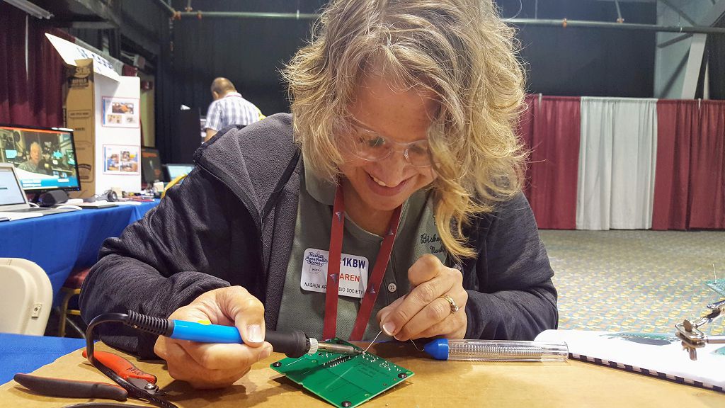
We owe a lot of thanks to Karen Crivac, KC1KBW who is a teacher at BGHS. Karen has been providing tremendous support and encouragement for our work to bring Amateur Radio to the students at BGHS. Karen holds a General Class Amateur Radio license.
Karen and the STEM club at BGHS were part of the ISS Contact that we did with Hudson Memorial School some time ago. Shortly afterward, Karen began working on securing an ISS Contact for her school.
The process of securing an ISS contact experience involved a lot of work to create a quality STEM-learning program leading up to and after a Contact with the ISS. Karen and the faculty at BGHS did a great job with this and were awarded a Contact late last year.
Contacts with the ISS are arranged by ARISS. I serve as both a Mentor and a Ground Staton as part of the ARISS program. I have had the pleasure of serving as the ARISS Mentor for the Bishop Guertin contact. The Nashua Area Radio Society is also BGHS’s partner Amateur Radio club. Jon Turner, AC1EV has been working closely with Bishop Guertin to help them to prepare for their contact.
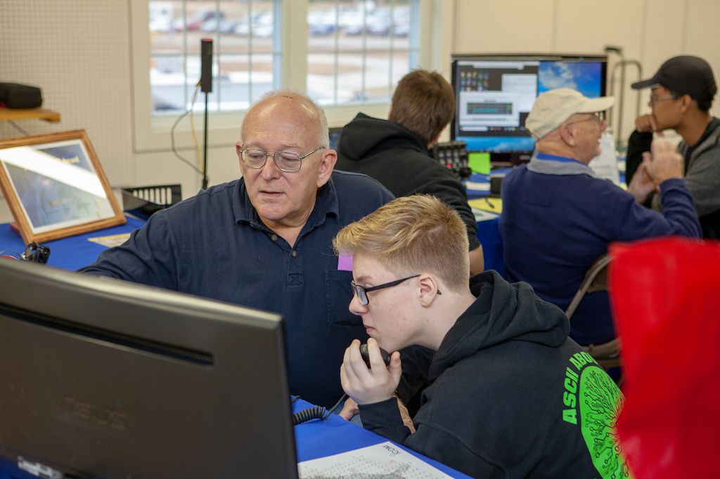
BGHS Calling NA1SS, Do You Copy?
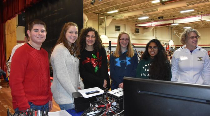
The students at BGHS have been working on creating questions to ask their Astronaut during their upcoming contact. Many BG students submitted candidate questions.
There is only time for about 20 questions to be asked during the actual contact so the students in STEM Club create the video above to answer some of the questions that did not make the final list for their contact. You can click on the video above to hear the questions and the answers from the STEM Club team.
Here are the questions that the students at BGHS are planning to ask their Astronaut:
- Aya, KC1JEB – What landmark on Earth looks the most amazing from space?
- Shea – What day to day task is most challenging in space?
- Brandon – What inspired you to become an astronaut?
- Ian, KC1ONS – What experiments are you currently working on?
- Christopher, KC1KBY – Can you share with us what you like best about being in space?
- Ella – What does a typical day look like for you?
- Connor- What is something new you learned in space?
- Ethan – What did you bring from Earth to remind you of home?
- Lindsay – What part of space travel is most exciting for you?
- Connor – Does being in zero gravity feel like floating in the water?
- Aya, KC1JEB – What are some recent discoveries the ISS has made from the experiments conducted in space?
- Shea – Upon returning to Earth, how do you plan to re-adjust to gravity?
- Brandon – What are your thoughts as you prepare for lift-off?
- Ian, KC1ONS – As an experienced astronaut, what advice would you give to a new astronaut heading to the ISS?
- Christopher, KC1KBY – How do you treat injuries or illnesses in space?
- Ella – Do you have a favorite space food?
- Connor – What is the most unusual thing you have seen in space?
- Ethan – What part of your training was most challenging?
- Lindsay – What happens to your tears in space?
- Connor – How do the sun and stars look different in space than on Earth?
T = 0 for Calling the ISS from Bishop Guertin H.S.
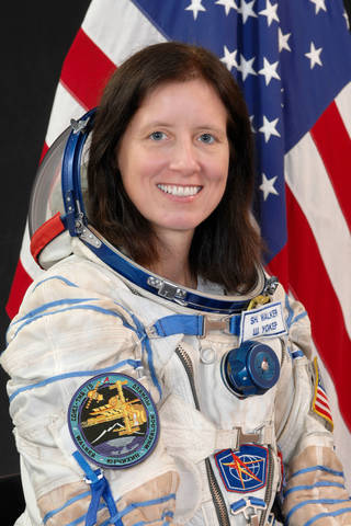
The pre-contact program for Bishop Guertin’s Contact will begin on Friday, February 18th, 2021 at 12:20 pm eastern time (17:20 UTC). The students at BGHS will be talking with astronaut Shannon Walker, KD5DXB who is onboard the ISS. The ISS will come over the horizon here in New Hampshire, USA at about 12:56 pm eastern time and will plan to make initial contact with Shannon then.
You can view the contact by clicking on the video above.
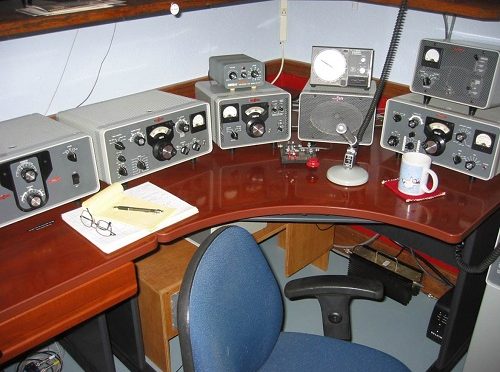
The Ground Station
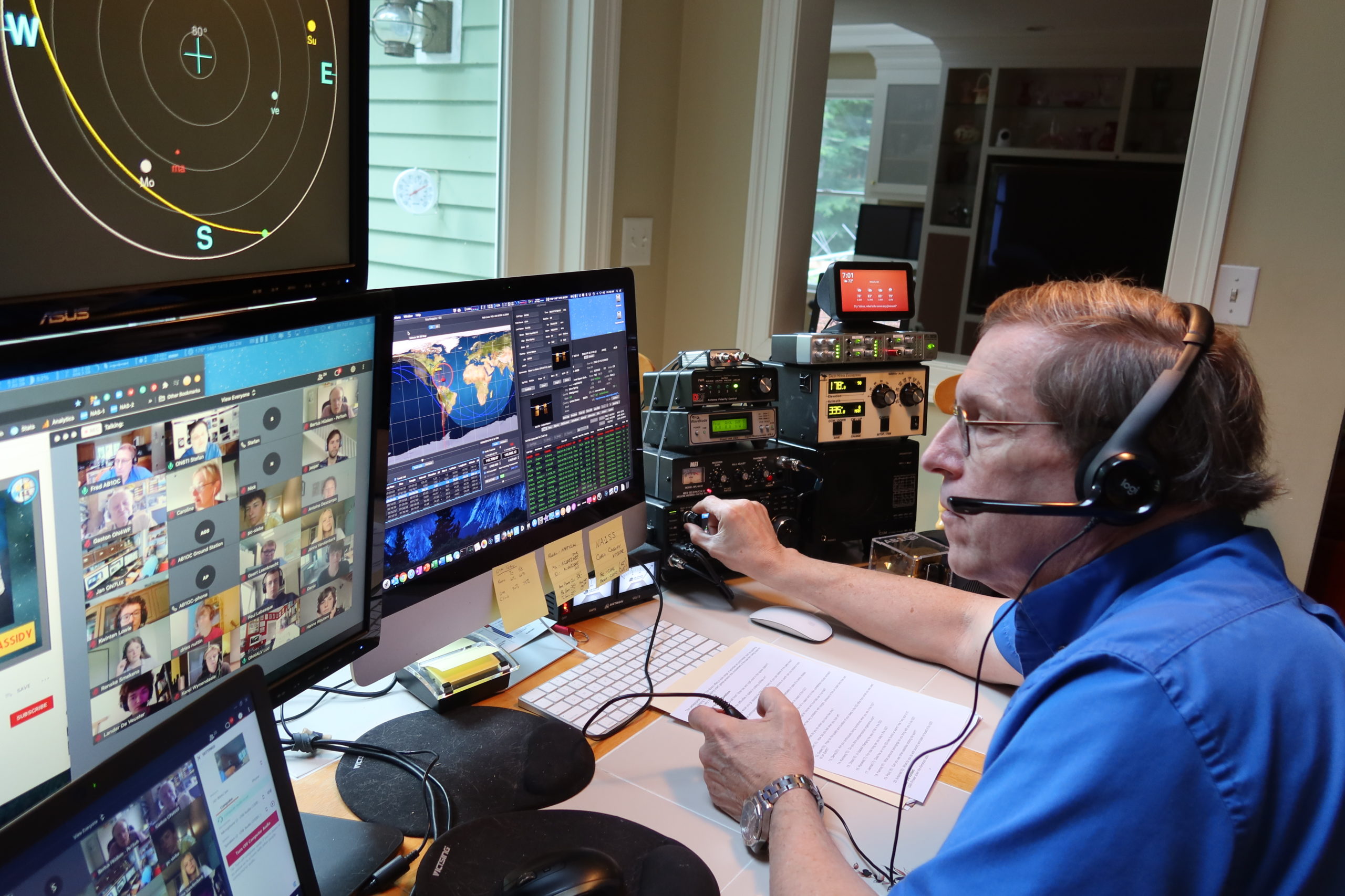
I also have the honor of serving as the ARISS Ground Station for BGHS’s contact. It will be my job to establish and maintain the radio link between the students at BGHS and the Shannon on the ISS while the students ask their questions.
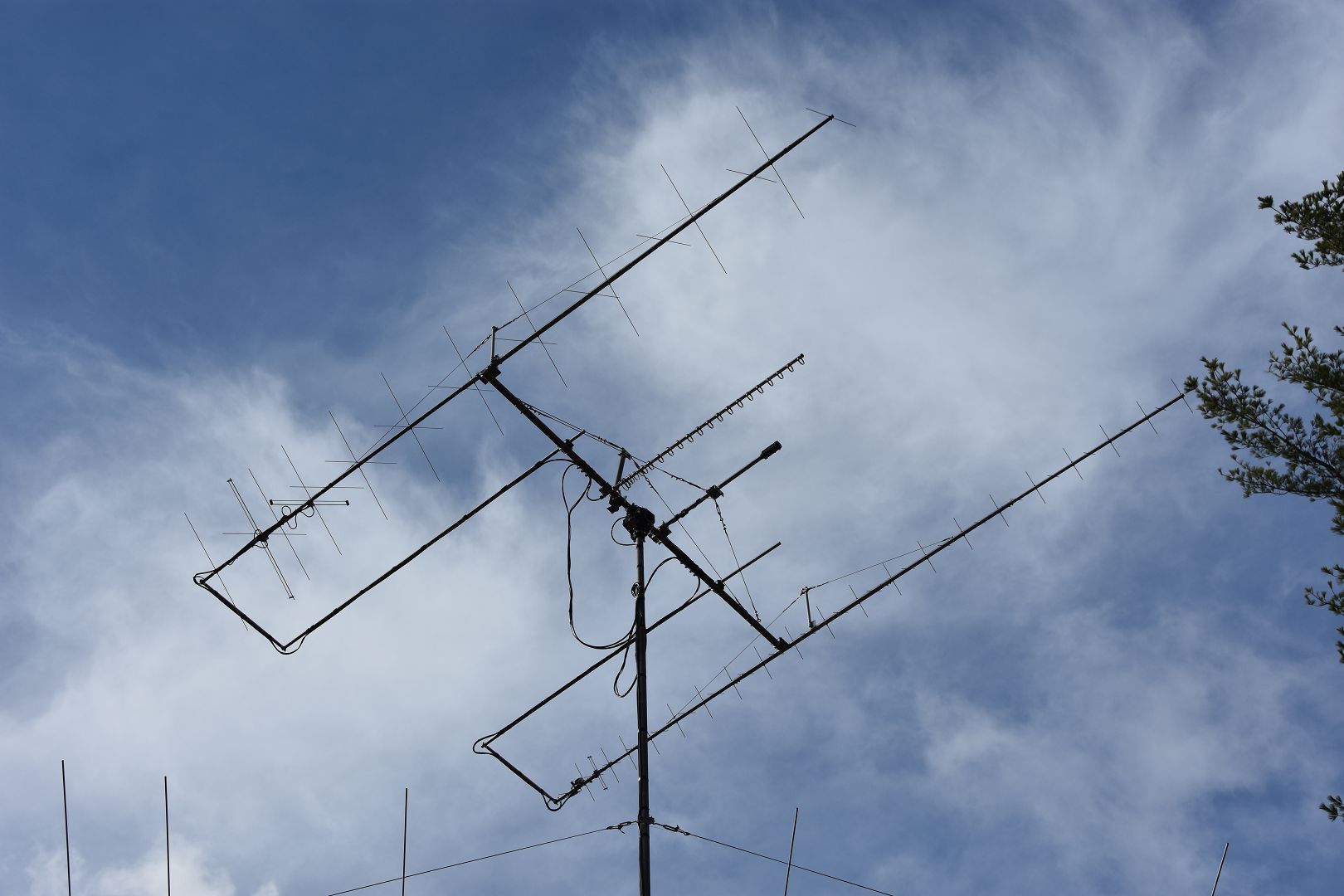
The station will be computer-controlled, enabling the antennas here to track the ISS during our contact. You can learn more about our Ground Station here.
Interested in learning more about our experience making contacts with the ISS? Check out this link for other ISS contact and activity articles.
The students have been learning much about space and radio technology in preparation for their contact with the ISS. The faculty and administrators at Bishop Guertin have also poured a great deal of time and energy into their contact. I hope that you’ll join us via the live stream and watch the students at BGHS make history!
Fred, AB1OC