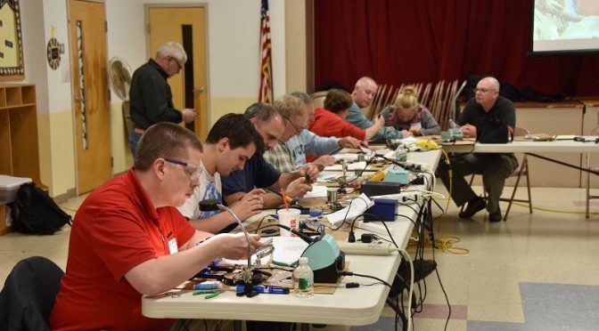
Connor (KC1GGX) and myself (Abby-AB1BY) both participated in the club’s November Tech Night. Our mission for the night was to build a 40m QRP CW Pixie Kit. Going in I was nervous – I had never soldered before – and wasn’t sure if I would understand how to put it together. Connor had done some soldering and was feeling more confident.
When we walked into the room Brian (AB1ZO) had all the kits neatly set out for everyone so we could get right to work. We opened the kits and instructions and I was overwhelmed! Thankfully we had some very experienced Elmers to help us out. Bill (K1TWO) and Charlie (AB1ZN) were extremely helpful in improving our soldering techniques and figuring out what went where. At first, I was very slow and asked a lot of questions, but as the night went on I think my technique got better and things went faster.
We worked the whole time and were the last two to finish, but when it came time to test our kits out they both worked! I was very proud of myself and learned a lot. Connor also had a great time and wants to do another project with soldering!
We would like to thank Brian and everyone involved for putting this fun tech night together.
Anita and I like to take advantage of the mild fall weather to do antenna projects at our QTH. We have completed two such projects this fall – the installation of a Two-Element Phased Receive System and a rebuild of the control cable interconnect system at the base of our tower.
The NCC-1 System can be used to peak or null a specific incoming signal. It can also be applied to a noise source to null it out. The direction that it peaks or nulls in is determined by changing the phase relationship between the two Active Antenna Elements via the NCC-1 Controller.
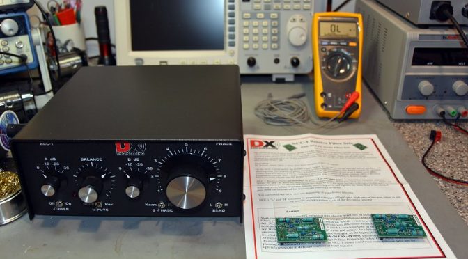
NCC-1 Filter Installation
The first step in the project was to open the NCC-1 Control Unit to install a set of 80m and 160m bandpass filter boards. These filters prevent strong out-of-band signals (such as local AM radio stations) from overloading the NCC-1. The internal switches were also set to configure the NCC-1 to provide power from an external source to the receive antenna elements through the connecting coax cables.
Receive Antenna Elements and Coax
Installed Active Receive Antenna Element
The next step in the project was to select a suitable location for installing the Receive Antenna Elements. We choose a spot on a ridge which allowed the two Antenna Elements to be separated by 135 ft (for operation on 160m/80m) and which provided a favorable orientation toward both Europe and Japan. The antenna elements use active circuitry to provide uniform phase performance between each element’s 8 1/2 foot whip antenna and the rest of the system. The antenna elements should be separated by a 1/2 wavelength or more on the lowest band of operation from any towers or transmit antennas to enable the best possible noise rejection performance.
Received Antenna Element Closeup
The two Antenna Elements were assembled and installed on 5 ft rods which were driven into the ground. To ensure a good ground for the elements and to improve their sensitivity, we opted to install 4 radials on each antenna (the black wires coming from the bottom of the unit in the picture above). The Antenna Elements are powered through 75-ohm flooded coax cables which connect them to the NCC-1 Control Unit in our shack. The coax cable connections in our setup are quite long – the length of the pair being approximately 500 ft. The use of flooded coax cable allows the cables to be run underground or buried. Should the outer jacket become nicked, the flooding glue inside the cable will seal the damage and keep water out of the cable.
Receive RF Choke
It is also important to isolate the connecting coax cables from picking up strong signals from nearby AM Radio stations, etc. To help with this, we installed Receive RF Chokes in each of the two coax cables which connect the Antenna Elements to the NCC-1. These chokes need to be installed on ground rods near the Antenna Elements for best performance.
Underground Cable Conduit In Our Yard
We ran the coax cables underground inside cable conduits for a good portion of the run between the antenna elements and our shack. The conduits were installed in our yard when we built our tower a few years back so getting the coax cables to our shack was relatively easy.
Receive Antenna Coax Ground System
The last step in the outdoor part of this project was to install a pair of 75-ohm coax surge protectors near the entry to our shack. An additional ground rod was driven for this purpose and was bonded to the rest of our station’s ground system. We routed both of the 75-ohm coax cables from the two Antenna Elements through surge protectors and into our shack. Alpha-Delta makes the copper ground rod bracket shown in the picture for mounting the surge protectors on the ground rod.
Shack Installation
Antenna Equipment Shelf In Our Shack (The NCC-1 Control Unit Is At The Bottom)
The installation work in our shack began with the construction of a larger shelf to hold all of our antenna control equipment and to make space for the NCC-1. The two incoming coax cables from the Antenna Elements were connected to the NCC-1.
microHAM Station Master Deluxe Antenna Controller
Antenna switching and control in our station is handled by a microHAM System. Each radio has a dedicated microHAM Station Master Deluxe Antenna Controller which can be used to select separate transmit and receive antenna for the associated radio. The microHAM system allows our new Receive Antenna System to be shared between the 5 radios in our station.
Antenna Switching Matrix
The first step in integrating the Receive Antenna System was to connect the output of the NCC-1 to the Antenna Switching Matrix outside our shack. We added a low-noise preamp (shown in the upper left of the picture above) to increase the sensitivity of the Antenna System. The blue device in the picture is a 75 ohm to 50-ohm matching transformer which matches the NCC-1’s 75-ohm output to our 50-ohm radios. The other two preamps and transformers in the picture are part of our previously installed 8-Circle Receive Antenna System.
Protection From Overload
Multi-Radio Sequencer
The Antenna Elements must be protected from overload and damage from strong nearly RF fields from our transmit antennas. In a single radio station, this can be handled via a simple sequencer unit associated with one’s radio. In a multi-op station such as ours, it is possible for a different radio than the one which is using the Receive Antenna System to be transmitting on a band which would damage the Receive Antenna System.
To solve this problem, we built a multi-radio sequencer using one of the microHAM control boxes in our station. The 062 Relay Unit shown above has one relay associated with each of the five radios in our station. The power to the Receive Antenna System is routed through all 5 of these relays. When any radio transmits on a band that could damage the Antenna Elements, the associated relay is automatically opened 25 mS before the radio is allowed to key up. This ensures that the system’s Antenna Elements are safely powered down and grounded.
On The Air Performance
NCC-1 Controls
So how well does the system work? To test it, we adjusted the NCC-1 to peak and then null a weak CW signal on 80m. This is done by first adjusting the Balance and Attenuator controls on the NCC-1 so that the incoming signal is heard at the same level by both Antenna Elements. Next, the B Phase switch is set to Rev to cause the system to operate in a signal null’ing configuration and the Phase control is adjusted to maximize the null’ing effect on the target signal. One can go back and forth a few times between the Balance and Phase controls to get the best possible null. Finally, the incoming signal is peaked by setting the B Phase switch to Norm.
Peaked And Null’ed CW Signal
The picture above shows the display of the target CW signal on the radio using the NCC-1 Antenna System. If you look closely at the lower display in the figure (null’ed signal) you can still see the faint CW trace on the pan adapter. The difference between the peak and the null is about 3 S-units or 18 dB.
NCC-1 Used For Noise Cancellation
The NCC-1 can also be used to reduce (null out) background noise. The picture above shows the result of doing this for an incoming SSB signal on 75m. The system display at the top shows an S5 SSB signal in the presence of S4 – S5 noise. Also, note how clean the noise floor for the received SSB signal becomes when the unit is set to null the noise source from a different direction than the received SSB signal.
We are very pleased with the performance of our new Receive Antenna System. It should make a great tool for DX’ing on the low-bands. It is a good complement to our 8-circle steerable receive system which we use for contesting on 160m and 80m.
Other Antenna System Maintenance
Tower Control Cable Interconnects (Bottom Two Gray Boxes)
Our other antenna project was a maintenance one. We have quite a number of control leads going to our tower. When we built our station, we placed surge protectors at the base of our tower. We then routed all of our control leads through exposed connections on these units. Over time, we found that surge protection was not necessary. Also, we became concerned about the effects that sunlight and weather were having on the exposed connections. To clean all of this up, we installed two DXEngineering Interconnect Enclosures on our tower and moved all the control cable connections inside them.
Inside View Of Interconnect Enclosures
We began with a pair of enclosures from DXEngineering and we mounted screw terminal barrier strips on the aluminum mounting plates in each enclosure. The aluminum plates are grounded via copper strap material to our tower.
Closer Look At One Of The Interconnect Enclosures
The picture above shows one of the interconnection boxes. This one is used to connect our two SteppIR DB36 Yagi Antennas and some of the supporting equipment. The barrier strips form a convenient set of test points for troubleshooting any problems with our equipment on the tower. There are almost 100 control leads passing through the two enclosures. This arrangement keeps everything organized and protected from the weather.
With all of our antenna projects complete, we are looking forward to a fun winter of contesting and low-band DX’ing.
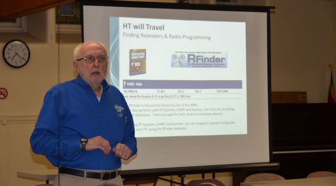
So you’ve gotten your Technician License or your General upgrade – how do you get a station on the air? This was the topic of our recent Tech Night. The following are some thoughts to get you started. If you are a new Technician, the first thing to ask is – “What do I really want to do on the air and where will I be doing it?” Here are some common answers to this question:
I spend a lot of time commuting in my car or truck and I’d like to pass the time talking with other HAMs
I will mostly be operating from my home and I want to rag chew (chat with other HAMs) and check-in to emergency, ARES and/or other nets
My plans are mostly be doing parade and other HAM activities in the field and I need something that is portable
Approaches for Tech Operators
In all of these scenarios, you will be using a combination of FM Simplex and Repeater operation on the 2 m and 70 cm bands.
Mobile 2 m/70 cm FM Radio in a Vehicle
If the first case is you, then you’ll want to install an FM mobile rig and antenna in your car or truck. You’ll also probably want to permanently mount a simple 2 m/70 cm antenna on your vehicle.
Base 2 m/70 cm Radio with APRS Display
If the second case is your prime operating scenario, then your choices in radios probably are along two main paths. A 2 m/70 cm radio or a dual purpose HF and 2 m/70 cm capable “all in one” radio. You might take the second approach if you already have or are planning to get your General Class or Extra Class license. A 2 m/70 cm ground plane style vertical antenna that you can mount outside or perhaps in your attic would be a good choice. You might also want to consider a radio that does D-STAR or another Digital Voice mode. There are some large worldwide nets that use digital plus internet linking to reach a large population of HAMs.
HT with Improved Antenna
If the third case is you main operating mode, then you probably want a quality HT with a good antenna. The rubber duck antenna that comes with most HTs will provide relatively weak performance. A quality 5/8 wavelength antenna and a spare battery for your HT will be a good way to go.
Approaches for General Operators
OCF Dipole and a 2 m/70 cm Antennas
If you’ve received your General Class license and want to do HF, your biggest decision will your antenna antenna. This topic is pretty broad and we’ll cover it in more detail at our Tech Night. I usually recommend a simple wire antenna to get started. A 20m dipole mounted either horizontally or vertically is often a good first choice. It’s inexpensive and can be put up at most QTHs in a day or less.
Moving up from here, a 40m delta loop or a multi-band OCF dipole also make great starter antennas depending on your space and what you want to do. If you cannot mount an antenna outside, you may be able to mount a modest dipole in your attic or use a portable antenna system like the Buddipole that you can set up to operate and then take down.
Basic HF Station with PC
Radio choice is also a broad topic which we will cover at our Tech Night. I would recommend a starter HF radio or a good used one (with help from an experienced HAM to select and check out). Your radio should be a 100W unit and cover all of the HF bands from 80 m – 10 m at a minimum. QRP radios (5 – 10W) are usually not a good choice for a first station. Making contacts at this power level with simple antennas can be challenging. It’s also good to have a radio which can do 6 m if that works out for you.
I highly recommend that you include digital mode capability in your first HF station. Digital modes such as PSK and RTTY provide a great way to learn to make contacts on the HF bands. Also, these modes work very well for making DX contacts with 100W and simple wire antennas.
I hope that this will get you started thinking about how to set your first station. Please come to our next Tech Night session to learn more. You can ask questions and get the benefit of experienced folks in our club. We can help you with these choices. We can also help with installing radios, antennas and getting on the air.
We use cookies to ensure that we give you the best experience on our website. If you continue to use this site we will assume that you are happy with it.
 Connor (KC1GGX) and myself (Abby-AB1BY) both participated in the club’s November Tech Night. Our mission for the night was to build a 40m QRP CW Pixie Kit. Going in I was nervous – I had never soldered before – and wasn’t sure if I would understand how to put it together. Connor had done some soldering and was feeling more confident.
 We worked the whole time and were the last two to finish, but when it came time to test our kits out they both worked! I was very proud of myself and learned a lot. Connor also had a great time and wants to do another project with soldering!