The nice part is that you can make changes as you see fit.
I made some changes and modeled the design in SolidWorks.
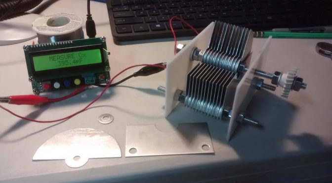
From SolidWorks, I made a sheet layout in FabriWIN. you can see spacer washers cut out of the “scrap”.
My .030″ aluminum rotors and stators only needed some deburring from the CNC turret punch press at work. I also did not make the spring loaded rotational contact. I just attached a ring terminal and some wire to the rotor shaft. Below is a cap that I will be testing in a home brew antenna tuner. I will increase the air gaps if I find it arcing. I’m not sure that will happen at QRP levels. The knob is an old plastic gear from an old printer. It prevents my fingers from changing the capacitance value.
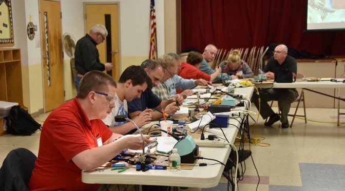
Connor (KC1GGX) and myself (Abby-AB1BY) both participated in the club’s November Tech Night. Our mission for the night was to build a 40m QRP CW Pixie Kit. Going in I was nervous – I had never soldered before – and wasn’t sure if I would understand how to put it together. Connor had done some soldering and was feeling more confident.
When we walked into the room Brian (AB1ZO) had all the kits neatly set out for everyone so we could get right to work. We opened the kits and instructions and I was overwhelmed! Thankfully we had some very experienced Elmers to help us out. Bill (K1TWO) and Charlie (AB1ZN) were extremely helpful in improving our soldering techniques and figuring out what went where. At first, I was very slow and asked a lot of questions, but as the night went on I think my technique got better and things went faster.
We worked the whole time and were the last two to finish, but when it came time to test our kits out they both worked! I was very proud of myself and learned a lot. Connor also had a great time and wants to do another project with soldering!
We would like to thank Brian and everyone involved for putting this fun tech night together.
It has been a couple of months since I wrote about my project to build a Moxon antenna for 15 and 17 meters in the attic of my garage. The weather has since cooled down to where I can work in the attic without sweat dripping in my eyes and my hands slipping on everything. When I wrote about my initial measurements in the last article, I was experiencing erratic SWR readings on the 15-meter beam with the lowest SWR being around 23 MHz. I did some recomputing and figured I would need to lengthen each element by 24 inches to bring resonance down to 21.1 MHz. I was not too thrilled with the idea of having to solder wires in the cramped space of the attic so I decided to check the SWR behavior again.
There is an old adage in carpentry that says measure twice, cut once. The same applies for adjusting antenna elements except “twice” becomes “until consistent”. When I connected my analyzer to the 15-meter beam, I did the flex test of the connecting cable. Lo and behold, the SWR started jumping around. I checked the connector hardware and noticed the PL-259 reducer shell was loose. Once I tightened it, I found the resonant point to be way down at 19.0 MHz. My antenna was too long; it would have to be SHORTENED by 24 inches.
Armed with the new readings, I shortened each element accordingly and measured the antenna again. My efforts paid off with a reading of 1.1:1 at 21.2 MHz and a 2:1 bandwidth from 20.8 to 22.78 MHz. I was now ready to move on to final installation.
I needed more coax, a couple of baluns, and a remote antenna switch to complete the project. A hamfest scheduled for the first weekend in October in Melbourne, FL looked like a good prospect for finding what I needed. Unfortunately, Hurricane Matthew had other plans and forced a postponement of two weeks. When I attended the hamfest, many vendors were absent due to conflicting plans so pickings were slim. I did manage to find the baluns and more coax but the switch would have to be ordered.
I found an Ameritron RCS-4 online at a reasonable price and ordered it. I had used this model for many years when in NH so I was familiar with its reliability. When the switch arrived, I hooked it up to check it out before installing it. Murphy said hello to me with a non-functioning control unit. I called the company I bought it from and they arranged to have it returned for a replacement. I finally received a working unit two days before Thanksgiving. With the CQ WW CW contest coming up, it came just in time.
I routed a 50-foot run of coax from my shack around the front of the house and into the garage attic. Figure 1 shows the coax run. If you can’t see it, good; I do not want the Village Vigilantes to come knocking on the door to question the aesthetics of the cable. Figure 2 shows a closer view of the coax entering my attic. So far, the XYL hasn’t noticed it so I’m safe.
Figure 1. Coax Run Across Front of HouseFigure 2. Coax into the Attic (Upper Left)
The next step involved hooking up the baluns and the remote switch which was a straightforward process. Once everything was in place, I fired up the rig on 17 meters and found a spot for UA0ZC. I was happy to hear him and gave Val a call. A minute later I had a rare one in the log without having to hammer away indefinitely. I checked 15 meters and did not find much activity. The operational SWR was a bit higher than my measurements but still under 2:1.
At least, it started out that way. I got on the air the next day and found the SWR on 15 meters hitting 6:1 and higher. I made a trip up to the attic to find out what was going on. At first glance, nothing appeared amiss. I plugged the analyzer into the 15-meter beam and noticed the SWR jumping around. Flexing the cable made some difference but not much. My initial thought had been some incomplete switching in the switch unit but the SWR behavior when directly connected to the analyzer ruled that out. I tried swapping baluns between the two beams to no avail. With other pressing holiday matters to attend to, I decided to remove a balun from the 17-meter beam in favor of the 15-meter beam. (During my troubleshooting efforts, I noticed the 17-meter beam behaved as designed, with or without a balun.) The 15-meter beam shows no discernible difference in performance with or without the balun. Figure 3 shows the present feed point installation with the switch on the attic floor.
Figure 3. Feed Points and Switch
I have to admit that I am stumped at this point. There is some consolation, however, in that my K3 tuner easily matches up the 6:1 SWR imbalance. I imagine there is interaction with the other structures in the attic (house wiring, AC ducts, 17-meter beams, etc.) that are making a good match difficult to achieve. At any rate, I am happy to have a worthwhile antenna for 17 meters vice my low inverted V. As the sunspots continue to degrade, 17 meters may well end up as the MUF.
We use cookies to ensure that we give you the best experience on our website. If you continue to use this site we will assume that you are happy with it.


 Connor (


")
