Category Archives: Homebrewing

Articles and other information related to Homebrewing, station building, kit building, and other custom Ham Radio projects.

Homebrew an Antenna Analyzer

If you’re like me, then you try to be judicious with your $$$. Ideally, it would be great to spend $ and get the highest quality in return. But, the world does not work this way. So, if I am going to spend $$$ (on a scale of $, $$, and $$$), I want to make sure not only am I obtaining quality, but also multi-functionality. In other words, it’s easier for me to spend more money when I feel like my purchase is not exactly a swiss-army knife but also not a one-trick pony.

I could be wrong, but antenna analyzers kind of feel like a one-trick pony to me. When I first strung up my Buckmaster 7-band OCF dipole, I borrowed the RigExpert AA-30 from Greg W1TEN, in order to measure the VSWR,  since I wasn’t thrilled about spending $200 for the analyzer. Especially because I would rather put that money towards a Heil headset and foot pedal (to be ordered for Xmas 2017).

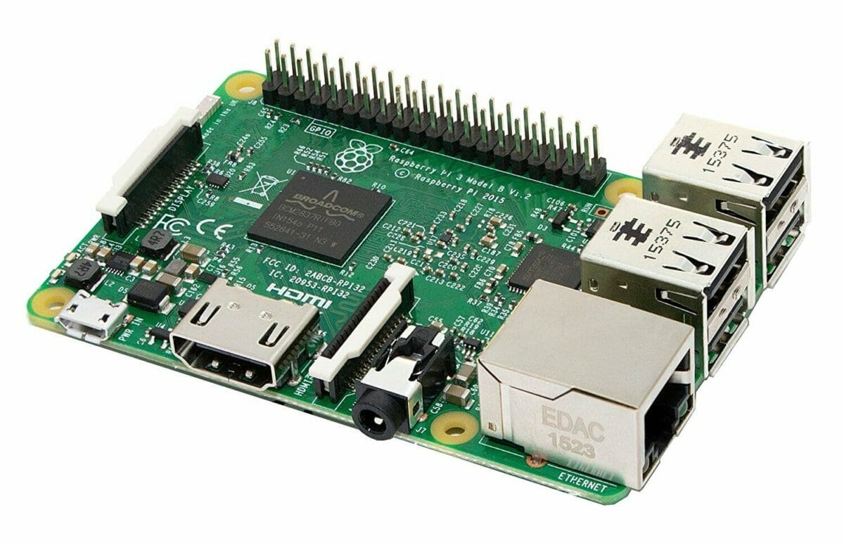
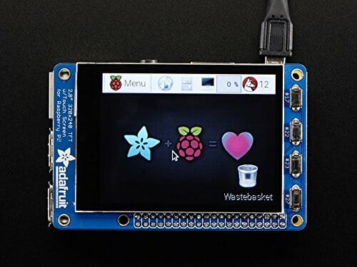
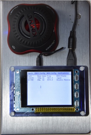
At the October Board of Directors (BoD) meeting, Fred AB1OC mentioned that in the Nov 2017 issue of QST, there was an article entitled “Build Your Own Arduino-Based Antenna Analyzer” by Jack Purdum W8EEE and Farrukh Zia K2ZIA. The attractive thing about this design is the authors quote a price point of $50. The major components are comprised of an Arduino, AD9850 Direct-Digital Synthesizer (DDS) board, and TFT display. Additionally, on the main website, one can also download the associated software to load on the Arduino. So, this leaves the user with the experience and satisfaction of homebrewing a really useful component for the shack. There seems to be a lot of documentation on the assembly, parts, etc. so this makes it relatively easy for the user.

Homebrew Antenna Analyzer
Completed assembly of analyzer
Homebrew Antenna Analyzer
View of Arduino, PCB, and components for analyzer

A downside is that the number of components required seems to be somewhat large as seen from Farrukh’s website which could potentially be overwhelming if you are just beginning. The authors also quote that one helpful component is purchasing their own custom PCB for the job itself. Though this is not essential, it may aid in the build.

Having not built this yet, I would say this would be an intriguing build for someone. I would certainly like to tackle it and have added it near the top of my to-do list since it seems like it can be accomplished within a weekend.

A Cheaper Alternative?

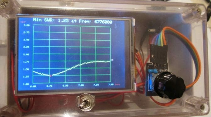
After I read the article, I emailed Mike AB1YK to let him know about it. He replied with yet another option in the form of a PDF by K6BEZ who claims to accomplish the same feat in < $50. Definitely attractive! It’s built on the same premise: AD9850 DDS board, Arduino, etc., but seems to use fewer components. Instructions also seem to be located here. 

Some pitfalls of the build from the PDF link provided above:

  • I located some Yahoo forums discussing that the analyzer as spec’d out did not seem to work for some builders. It’s unclear if the schematics were incomplete or if it’s due to another reason entirely.
  • The build does not seem to be that much cheaper. For instance, the PDF lists the AD9850 DDS as being $4 on eBay. Having looked there myself, as well as on Amazon, the going rate seems to be in the neighborhood of $18-$19. Given this, along with looking up some of the other items in the bill of materials, the price point seems to approach $50 pretty quickly.

If I endeavor upon this, I will be sure to document and write another article about it. If someone attempts the “cheaper option”, I would be interested to hear how well it works.

Happy building!

Brian AB1ZO

DX Alarm Clock Part 2 – Hardware

I recently wrote a blog article about the DX Alarm Clock software – here is Part 2 of the Series on the how I built the hardware for the DX Alarm Clock.

DX Alarm Clock Hardware Components

The DX Alarm Clock is based on a Raspberry Pi 3 computer and an Adafruit Pi-TFT Touch Screen Display.  The list of components, along with links is below.  Since I built the Raspberry Pi almost a year ago and technology is always advancing, some of the parts are no longer available or have better replacements available.  I’ll provide information on what I used and a recommended replacement.  Approximate prices are included.

Raspberry Pi 3
Raspberry Pi 3

Motherboard: Raspberry Pi 3 ($35) – includes a 1.2 GHz 64-bit quad-core ARM CPU, Build in WiFi, Ethernet, 4 USB Ports, an HDMI port and audio port (3.5″) and Bluetooth.

Also, you will need a power adapter  ($10) and Class 10 Micro SD card ($15) for the Raspberry Pi.  Ours is a SanDisk Ultra 64GB Micro SD Card.

Pi-TFT Touch Screen Display

Display: Adafruit Pi-TFT 2.8″ Display with Capacitive Touch Screen ($45).  A slightly larger, 3.5″ display is now available.

PiBow Case
PiBow Case

Case: Pimoroni PiBow Case for Raspberry Pi and Pi-TFT Display($20)

Kinivo Speaker
Kinivo Speaker

Portable Speaker:  Any small portable/rechargeable speaker will do.  Mine is a Kinivo, but it is no longer available.  Any small speaker will do as long as it is Bluetooth or has a 3.5″ stereo connector.

Completed DX Alarm Clock Hardware

The picture above shows the completed DX Alarm Clock Hardware running portable using a USB battery pack.

Raspberry Pi Development Environment

Raspberry Pi Development Environment

After constructing the Raspberry Pi, case and TFT Display, the next step was to connect it to a monitor via the HDMI port, a mouse via one of the USB ports and to a Bluetooth keyboard.   Then I loaded the Raspbian Operating System onto the Raspberry Pi via the micro SD card.  I first copied the OS to the Micro SD card using a PC or Mac and then inserted the card into the Raspberry Pi and booted from it.  You can find a good tutorial on how to do this at https://www.raspberrypi.org/learning/software-guide/quickstart/

Once Raspbian is installed, you will have a windows like GUI (Graphical User Interface) environment with a web browser, and a number of additional applications included.

This gave me a development environment that I could use to build and test the DX Alarm Clock software.  I used the Python language to develop the software.  I used the Python IDLE development environment, which is included in the Raspbian OS.

Interested in Raspberry Pi Amateur Radio Projects?  See the article on a Raspberry Pi Satellite Rotator Interface.

Raspberry Pi Satellite Rotator Interface

We’ve been using our Portable Satellite Station 2.0 for some time now and it works great. One area that can be improved is the interface between the MacDoppler Satellite Tracking program we use and the GHTracker application which controls the Green Heron Engineering RT-21 Az/El Rotator Controller in our setup…

Source: Raspberry Pi Satellite Rotator Interface | Our HAM Station

The Raspberry Pi is an inexpensive computer and control platform for many Ham Radio projects. We recently used a Raspberry Pi 3 to build an interface between the MacDoppler Satellite Tracking Software in our Portable Satellite Station and the Rotator Control System points the ground station antennas during satellite tracking. We put together an article about how we went about this project and some details of the hardware and software we used to put a Raspberry Pi 3 computer together for our project.

Fred, AB1OC

Radio Amateurs Developing Skills Worldwide