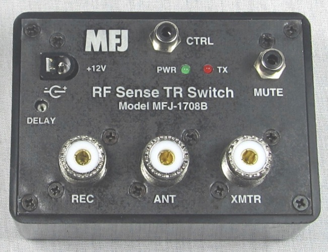
In my last post, I discussed how to add an SDR to your station using the built-in capabilities of your radio. If your radio doesn’t have this fancy antenna switching and selection feature, you can still integrate an SDR pan adapter into your shack using the handy MFJ-1708B or MFJ-1708B-SDRS devices.
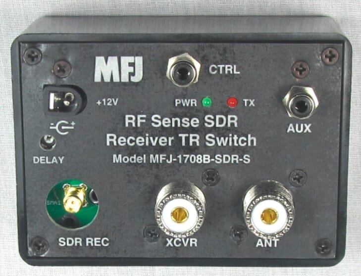
Antenna sharing device from MFJ
These devices can be used to allow your SDR to share the same antenna as your transceiver while protecting it from transmitted signals. It does this in one of two ways (or a combination).
Key down input. Transceivers have a line that is used to trigger external amplifiers called key down or key out line. Usually, this line goes to ground when the transmitter is transmitting. (You should read your radio’s manual to verify this.) If you connect this device to this radio output then it will disconnect the SDR while you transmit.
The device also has an RF sensing circuit that will disconnect the SDR from the antenna if it detects the transceiver transmitting.
Because these units use relays you might want to have a slight delay before reconnecting the SDR to the antenna after a transmission. That delay time can be selected by turning the “DELAY” control near the left edge.
The unit is simple to configure: connect power (12v) and your radio key out signal to “CTRL”, then connect your transceiver, SDR, and antenna connections to the proper ports. Finally, adjust the delay control until it works for your style of operating. That’s it!
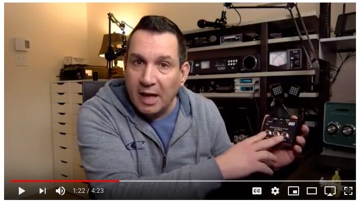
Here’s Pascal, VA2PV, with a quick overview of an earlier version of these devices.
Click the video above to see Pascal describe these devices
Note that Pascal is reviewing one of the earlier models of this device. MFJ made some improvements to these units almost immediately after they began shipping. Be sure to get the one with a “B” after the numbers to ensure you get the new-and-improved model.
MFJ actually makes two versions of the new model: one with a regular SO-239 connector for the SDR, and one with an SMA connector for the SDR. The SMA version is shown below.
SMA version of the unit
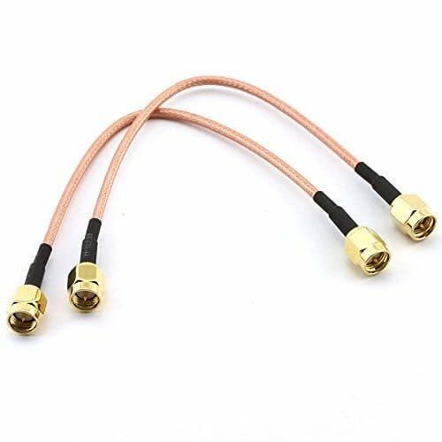
Amazon has some nice patch cables for very little money to complete the project.
SMA patch cables
Note: If you do have an external amplifier be sure to put the MFJ unit between your transceiver and the amplifier!
I’ll post a few more notes on SDRs and uses for them in your shack over the next month or so. Please plan to join us for the December 11th Tech Night SDR workshop where we’ll help you get your computer and SDR talking.
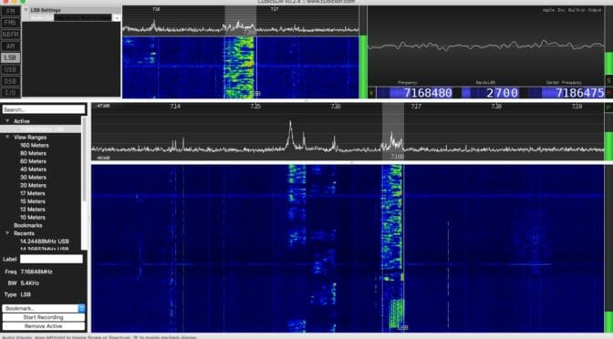
Having SDR capabilities like a waterfall display and point-and-click tuning can be added to your existing station. I’ll show you one easy way to do it.
Waterfall from an SDR
Antenna port management
Care must be taken that your SDR is protected from your transmitted signal. If you are sharing an antenna between your rig and an SDR receiver you need to ensure that your transmitted signal doesn’t go directly into a receiver! Years ago hams had receivers and they had transmitters. They switched between the two as they worked. The receiver was isolated from the transmitter while transmitting. Your transceiver does the same thing. It uncouples the receiver from the antenna when you transmit.
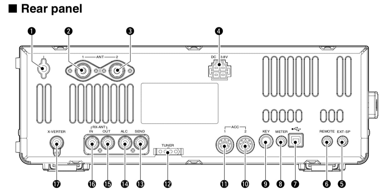
Some radios allow you to tap into the receiver’s receive path. My ICOM IC-7600, for example, has two RCA connectors labeled “RX ANT IN” and “OUT.” The IN and OUT are normally connected together. That is the default and in this condition things work exactly as you expect. But, you can select an option that separates these two signal paths.
RF in and RF out connectors on an IC-7600
Figure 1. Refs 16 and 17 are RX ANT IN and OUT, respectively.
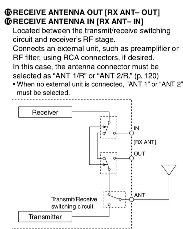
Figure 2 shows this relationship a little better.
ANT IN / OUT
Figure 2. Receive signal management in an IC-7600
If you had a receive-only antenna (like a Beverage) then you would separate the path, isolating your receiver from the transmit antenna, and sending it instead to your receive-only antenna (Connected to IN.) That configuration shown in Figure 2 is the default where the receive and transmit antenna are the same. If the relays around IN and OUT were switched the other way, the connection from the receiver to the transmit antenna can never happen. That’s how we ensure our receive-only antenna is used during receive. (It would be connected to RX ANT IN.)
Splitting the signal
In this exercise we’re going to add an SDR to the mix, not a receive antenna, but we use all the same stuff. What we need to do is tap into the received signal for the SDR without disturbing (too much) the signal that goes into the receiver of the ICOM. That is, I want to take the one signal (from the antenna) and split it between two receivers (the ICOM and an SDR). There is a device that does that and I’ve pictured it in Figure 3.
Mini-Circuits ZFSC-2-6+ Signal Splitter 0.002 to 60 MHz
Figure 3. A Mini-Circuits signal splitter.
This device is about as simple as something like this gets. The Mini-Circuit ZFSC-2-6+ takes one input and splits the signal to two outputs. So, we take the signal received from RX ANT OUT, send it to the splitter, and then take the two outputs and route one back to RX ANT IN (for the ICOM) and the other to an SDR. Now all you need to do is ensure your radio is using ANT 1/R or ANT 2/R so the signals remain split.
Choosing an SDR
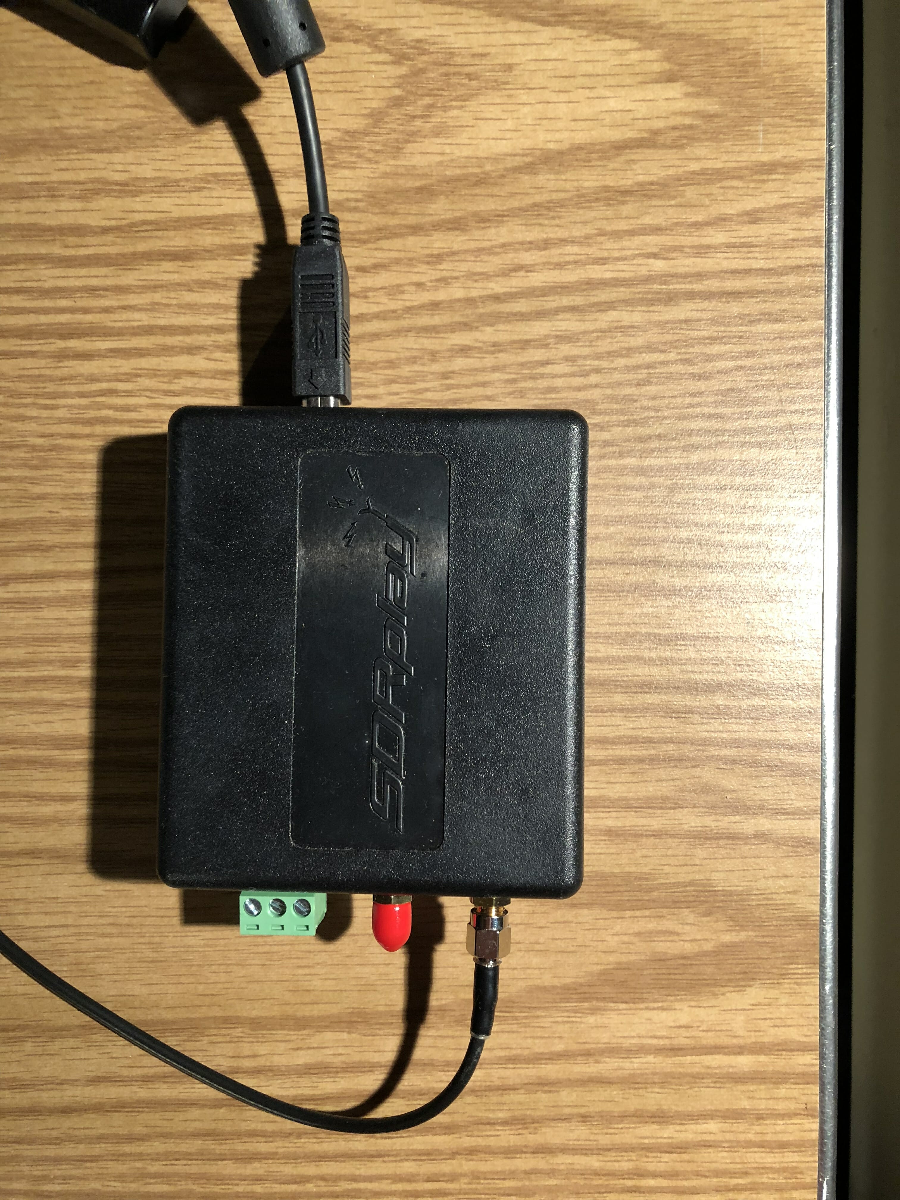
There are many, many small SDR receivers available. I selected the SDRplay RSP 2 receiver as shown in Figure 4.
SDRPlay RSP 2 receiver
Figure 4. The SDRplay RSP2 receiver
The antenna connection comes from one of the ports of the signal splitter. The unit is powered by, and communicates to, the computer via the USB cable shown near the top. This is a small unit and I tuck it neatly behind some other stuff and out of the way. There are no controls on the unit so there’s no reason to handle it again.
Software
Just as there are many choices for SDR receivers, there are many many choices for software. Ask any ten hams which one is best and you’ll likely get eleven answers. So, I recommend trying a few for your platform (I’m on a Mac) and see which one you like best.
SDRplay recommends CubicSDR and I’ve found the software fairly easy to use with an easy learning curve. SDRplay has software for the following platforms:
Windows
Linux x86
Mac
Raspberry Pi
Android
ARM64
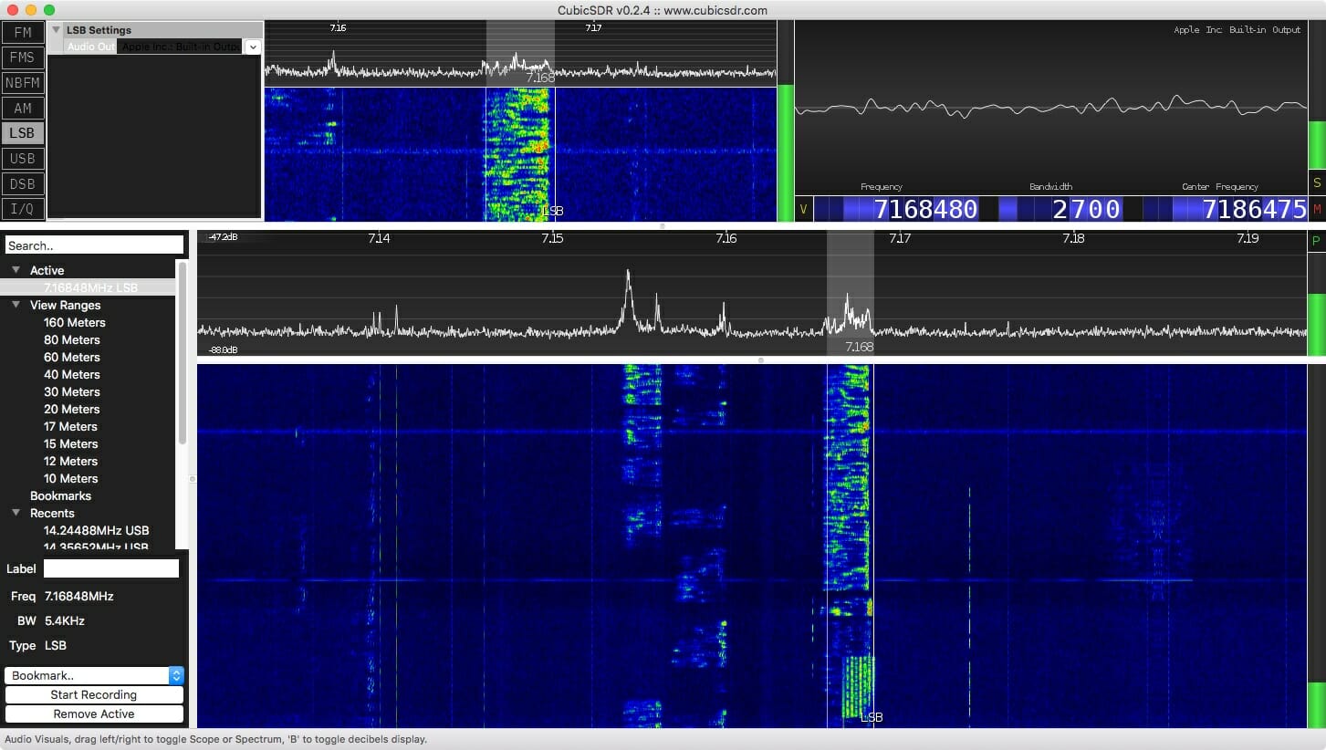
A screenshot of CubicSDR is shown at the top of this article.
The software allows me to see a wide slice of spectrum, a waterfall showing a history of signals, point-and-click tuning (once you’ve enabled rig control), and, of course, it is a receiver so it gives me sound from the tuned signal through my computer speakers.
Performance
The splitter has very little insertion loss (0.3 dB), but of course the signals themselves will each be down about 3 dB (since each signal is half the original). A loss of 3 dB is about half an S-unit, so you’ll never hear the difference. And, since the SDR is much more sensitive than my ears I consider its addition a win.
Impressions so far
I used this system while playing in the California QSO Party. It was fun clicking on a signal in the waterfall and having the radio obey my request. Hard-core SDR fans will likely talk about the power of visualization for finding a signal, or even finding open spots if you wish to call CQ. With this arrangement, you can have all that using your existing radio.
Coming in December
Would you like to try building an SDR for about $25 plus a Raspberry Pi? Come to the December Tech Night where we’ll have an SDR workshop. More detail on this to follow in a few weeks.
Although I am brand new to the hobby of ham radio, I have been playing around with electronics and digital circuits for as long as I can remember. I am a software engineer by trade and have always loved the problem-solving challenges that software and hardware engineering offers.
Given my unfamiliarity with the ham radio world, however, I thought it might be fun to find a project in that space. Enter the Daiwa CNW-419 manual tuner.
Our Next Victim
My father found this poor soul on eBay, and it was in a bit of a bad way. It had some missing feet, the tuner button “didn’t work”, and there seemed to be a couple of loose pieces in the pictures, but generally the interior of the tuner looked very clean.
After looking up some reviews of the tuner and finding nothing but praise, I thought what the heck, paid the $75 and took the plunge.
It arrived carefully packaged, and after unwrapping it, I found that the tuner switch was indeed broken. In addition, the switch to change the antenna (it supports two antennas), didn’t seem to be working properly either. Both of the switches were push buttons, and neither of them would latch.
Taking It All Apart
A first look under the covers
Time to take the cover off and see what was going on. With just the top cover off, we can see the two problematic switches in the back. If we’re going to get to those switches, a lot more stuff is going to need to come off.
After removing the bottom, and disconnecting the back panel, we get a better view of the switches. Some black charring there, perhaps some RF arcing took place? Looking at the rest of the box and how neat and organized the soldering and wiring is, this looks out of place. I am beginning to suspect something is amiss here.
After pulling the switches completely out, there definitely appeared to be some sort of overload. Or perhaps just bad soldering? More investigation is clearly required.
Our problematic switches
The Game is Afoot
Examining the part number for the switches I pulled out, I was able to find the equivalent switch on DigiKey. The schematic for this switch indicated that it was simple non-latching push button ON-ON DPDT switch. Clearly not the original part, as the tuner front panel artwork indicates that these are latching push button switches.
At this point, I headed back to google to see if I could find what the original switch was, but could find nothing. Finally, I stumbled across an interior shot of the tuner from a guy in Thailand. After some zooming, it looked like an ordinary latching switch.
But First Some Math…
The tuner is rated for a maximum of two hundred watts, so we should figure out what our switches need to be able to handle. We don’t want to trust the previous components ratings since they were not original.
One hundred watts at fifty Ohms yields an RMS voltage of about seventy volts which is what my receiver puts out. Since the tuner is rated to two hundred watts our max RMS voltage should be one hundred volts. 125VAC switches are plentiful, and to be safe we should also probably shoot for a switch that can handle around five amps. Eight dollars and fifty-two cents later, we have a pair of switches rated at 125VAC and seven amps. Perfect.
Putting It All Together
I took lots of photos and notes while removing the switches but knowing that they could have possibly been installed incorrectly, I took a little extra care in laying out the connections for the new switches.
The switch for the antennas was straight forward enough. This was simply a DPDT doubled up and wired as a SPST with the center poles connecting to the center pole output of the tuning circuit switch.
The new switches installed
The switch for the tuning circuit was a little peculiar. When the tuning circuit is disengaged, the switch should connect the output from the amp making sure it passes through the metering circuit and bypasses the tuning circuit. Originally, the switch connected the first pole to the second pole of the switch using only the thin wire of a small capacitor hanging down. This was clearly insufficient, and somewhat dangerous as that thin wire would be passing the full power RF output of the amp. I suspect this probably happened at one point as the capacitor wire was extremely brittle, and broke after I removed it.
A Puzzle for Our Readers
The dangling capacitor was likely a power filter circuit (that’s my guess). You can find these on regular power circuits where a high voltage cap connects the power to ground. I assume they are also used on RF power circuits. Is this correct? Ham radio experts feel free to chime in. I tested the untuned circuit path both with and without the cap filter but could discern no difference. I suspect it might have been affecting my output signal, but I had no way to test that. In the end, I left it connected, figuring I would not do much transmitting with the tuning circuit disabled.
Tuning it Up
Time to test it out. Here it is with some new rubber feet from the hardware store ($2.47) sitting on top of my FT-450D.
The new, and the slightly less new
I purposely detuned my vertical, disabled the ATU on my receiver and checked the SWR. Infinite SWR readings for both the tuner and my receiver. Great. The auto tuner on my receiver can’t touch that. I then enabled the tuning circuit on the Daiwa, found the best band setting, and tuned it up. In no time I had the SWR down to one, and the forward power at maximum.
I love this thing.
Radio Amateurs Developing Skills Worldwide
We use cookies to ensure that we give you the best experience on our website. If you continue to use this site we will assume that you are happy with it.

![Add SDR Capabilities to Your Radio [part 2]](https://www.n1fd.org/wp-content/uploads/2018/10/MFJ-1708B-651x372.jpg)
 Click the video above to see Pascal describe these devices