Nashua ARC will be hosting its first Youth Outreach event on Saturday, October 1 from 8am-2pm at Mine Falls Park in Nashua, NH. Mine Falls Park is located on Whipple St.
Mine Falls Park hosts many youth soccer games every Saturday throughout the Fall. We are hoping to take full advantage of that fact in order to provide kids a bit of insight into what comprises amateur radio.
Some of the activities that we will likely host are:
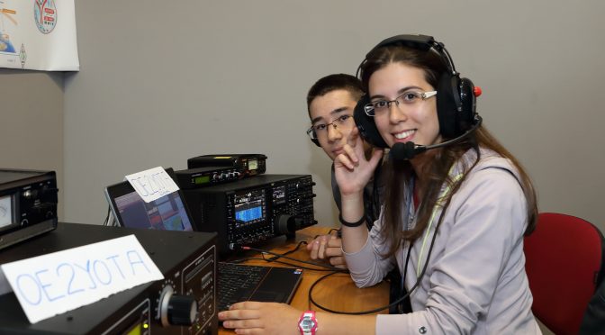
Get-On-The-Air (GOTA) Station
Fox hunts
Use some HT’s and get on the Nashua repeaters
This we hope is to generate enough interest so that we can plan a follow-on activity a bit later.
Now comes the part where AB1ZO looks at you warmly, scratches his cheek, and asks you for a favor. It might go down something like this:
A friendly, casual conversation between me and you
And that favor is that we really do need your help to come out to the Park:
Help us set up beginning around 8 am
(Setup is pretty important to have able bodies around for. We’ll shoot to get on the air as quickly as possible after. Perhaps by 9 am)
Work the booth
(Most importantly) Interact with the kids.
Help breakdown around 2 pm
The more the merrier and the longer you’re able to give a bit of time, the better as well. Additionally, you are completely encouraged to bring family and friends, especially if they are < 18 years old. But in all honesty, I think it would be fantastic if we had a significant contingent of the club at the Park, to welcome our guests. But don’t do it for me, do it for the kids:
Do it for the kids…
If you think you can give some time, please contact myself ([email protected]) or Jamey (KC1ENX) to let us know what you would like to help with. Again, we really could use the volunteers in all the aforementioned areas. We’re hoping this is a facet of the club you will all embrace as it evolves.
A few months ago, I wrote an article on building a stealth antenna farm. Since I live in the land of CC&Rs, antennas must be “dual use” such as a vertical hidden inside a PVC flagpole, or low dipoles and inverted Vees hidden in trees. I spent many years as an avid contester and DX-chaser to appreciate the logic of stacked beams on towers to enhance the thrill of the hunt. Thanks to Layne, AE1N, I checked out the website of Jeff, AC0C (www.acoc.com) for some ideas of how to build a multi-band station in one’s attic without the condo association vigilantes running him out of town. Jeff spent countless hours crawling around his attic to construct multi-element antennas for 160 through 6 meters. Spurred on by Jeff’s success, I decided to explore the attic of my garage to see what I could do. As I described in the MAY Nashua ARC bulletin, I settled on building Moxon antennas for 15 and 17 meters.
An old adage about antenna building states that an antenna must be built-in lousy weather in order to work right. Thirty years in New Hampshire lent credence to this axiom as I spent many a cold, windy day on a tower doing antenna work. In Florida, a similar law applies: build an antenna in the summer months while sweating profusely rather than during the comfortable winter weather. Again this makes sense: DX and contesting fill up the winter months to have time to mess with antennas. It is also important to remember that, during such endeavors, you will become enamored with you antenna as you take breaks to warm your body (in NH) or drink a gallon of water (in FL), all the while cursing this law of antenna building.
But I’m getting ahead of myself. My garage attic is roughly 20 x 20 feet with an apex of about five feet that runs north-south. I had selected the Moxon design because a conventional 2-element beam would not fit in the space available. I elected to build a Moxon for 15 and 17 meters that would fit in the space available without having to encounter obstacles like the ventilation duct work. I was also fortunate in that my home is one of the older models that do not have foil-backed insulation inside the roof that creates a radiation-proof box. The joists junctions are reinforced with metal plates as part of hurricane building codes. My plan was to attach the wires to the roof trusses and stay away from these plates as much as possible to avoid interaction.
The 17-meter Moxon is a little over seven feet between elements while the 15-meter Moxon is about six feet between elements. I used a piece of half-inch PVC pipe as a template to mark the joists for the 17-meter antenna. The antenna is about 2.5 feet above the attic floor for a total height of eleven feet above the ground. I had modeled it at 13 feet so I figured it would be close enough. The 15-meter Moxon is about 15 inches above the 17-meter one. When viewed from the top, the antennas look like concentric rectangular loops.
Over the course of several weeks, I grunted, groaned and sweated my way back and forth measuring and installing the wires. I worked during the morning hours before I was soaked before 10:00 AM. I found myself wishing I could have my five-year-old grandson help me. He can stand upright and is plenty flexible to maneuver around the joists. While I did not have to worry about the obvious safety issue of working on a tower, I did at times feel I was a candidate for the NFL concussion protocol from bumping my head. I tried using my cycling helmet but it interfered with my headlamp. Another similarity to tower work is that I had to make N trips back and forth in the attic for stuff I forgot. This is, however, much more bearable that climbing up and down a tower to get what I forgot.
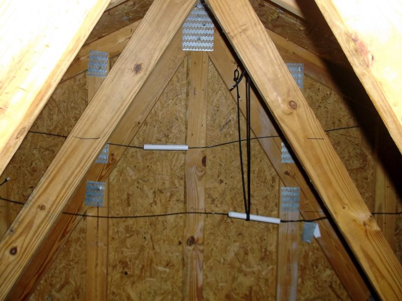
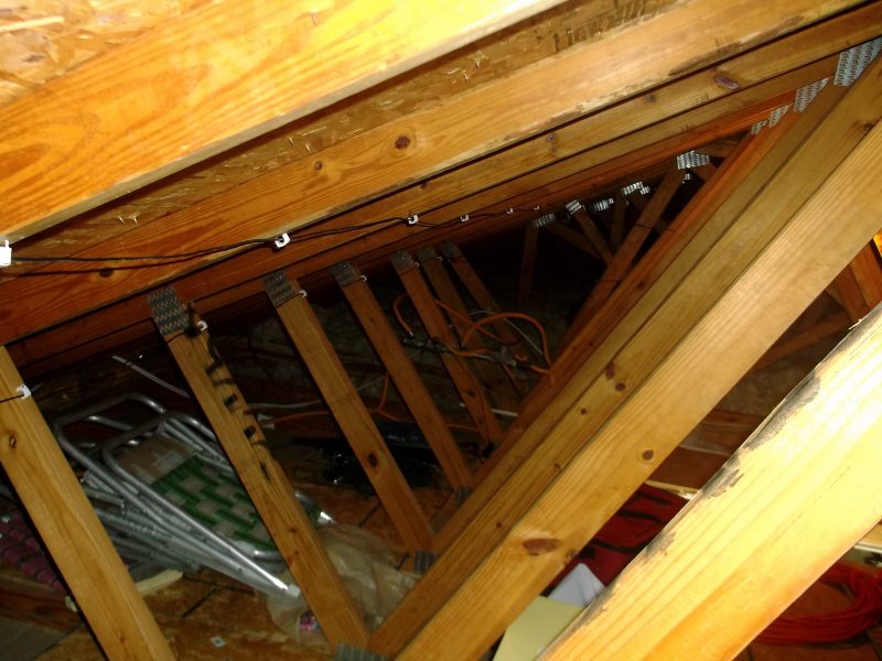
Figure 1 shows a view toward the south end of the attic. The two pieces of PVC form the element separators for the 15-meter Moxon (top wire) and the 17-meter Moxon (bottom wire).
Figure 2 shows the reflector elements for each antenna as secured to the joists, looking north through the attic. The white standoff fasteners are coax cable tie-downs that I found at the hardware store. Standard house wiring fasteners would have worked but they leave little room for pulling wires if I needed to make adjustments. (My first attempt was to use duct tape to hold the elements up. However, the heat soon made them droop.)
Figure 3 shows one corner of the director of each antenna looking east. The duct work to the left is part of the ventilation system while the open duct vents directly from the garage below. The yellow fence standoff on the upper antenna is the bend point for one end of the 15-meter director. Not visible to the left is a similar bend point for the 17-meter director.
Figure 3 – Looking East-from the Reflectors
Figure 4 shows the temporary feed points for each antenna.
Figure 4 – Feedpoint for 15m (top) & 17m (bottom)
The figures above show the project to date. I installed the 17-meter antenna first and measured its SWR performance with my analyzer. I found that it resonated beautifully at 16.7 MHz with a 1.1:1 SWR while bulging to 3.9:1 at 18.1 MHz. I shortened each element by a foot and ran measurements again, this time the resonant point moved up to 17.3 MHz (1.3:1 SWR) and the SWR at 18.1 MHz dropped to 2.7:1. I folded the elements back another four inches on each end and measured the response. I observed the SWR bottoming out at 1.5:1 at 18.1 MHz where I wanted to be. As a point of interest, I modeled a Moxon designed for 16.7 MHz and noticed the elements were about two feet longer than a Moxon designed for 18.1 MHz, close to the twenty inches I had to shorten the elements. Apparently, there is some interaction with the wiring that runs along the attic floor near the edges.
Armed with the satisfaction I was on the right track, I installed the 15-meter Moxon above the 17-meter antenna. I hooked up the analyzer and fired it up only to find to that its “resonant” point was a dismal 3.0:1 SWR at 22.9 MHz, rising to 3.9:1 at 21.1 MHz. This meant my antenna was too short. I went back to EZNEC, opened the standard dipole model and plugged in 22.9 MHz and found that its length was very close to the overall driven element for a Moxon designed for 21.1 MHz. I lengthened each element by five inches as a starting point to see what would happen. The result was no change in SWR at 22.9 MHz while dropping slightly to 3.6:1at 21.1 MHz. Hmm, looks like I need to get a little smarter about this.
Stay tuned for Part 2 to find out. (Don’t you hate that?)
At our most recent Tech Night meeting on Sept 12, at the end of the meeting, Fred (AB1OC) asked Brian (AB1ZO) to list a few of the upcoming tech night events.
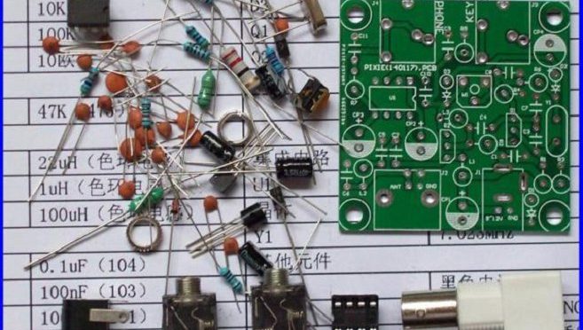
One such event would be to host a kit-building tech night. Plans are in the works to secure Pixie QRP kits (which run in cost from $3-$13) or some variant of this and assemble the kits during the allocated time. It’s expected that more experienced HAMs can mentor newbies in endeavors such as these.
Secondly, an informal poll was asked of members in attendance regarding the types of topics that would be of general interest. These included:
Low-band antenna discussion: Due to the decreasing sunspot activity, “40m is becoming the new 20m”. What options to HAMs have to get on the lower bands, particularly if you are real-estate limited?
Receiver vs Transmit antenna discussion — options for both
High-frequency terrain analysis (HFTA) in order to better understand propagation effects of one’s signal
Making sense of the influence of sunspot activity on amateur radio in general. Some energy, for example, could be dedicated to interpreting the sunspot GUI that appears on the website after login and understanding the science of the ionosphere.
Working more with test-equipment kits and how to use them. This may include oscilloscopes, spectrum and network analyzers, frequency counters, signal generators, building CW paddles/keyers, and soldering kits.
Using RTL-SDR dongles (or again some variant) and using them in small DIY projects that we could potentially complete in the allotted time.
I do want to say a few other things:
Since our club is growing, and many new people are joining, I do want to stress that it is important that sometimes we “recycle” old Tech night topics in an effort to better educate our newer members. In this capacity, I would again hope that veteran members could help train younger ones. For example, I cannot solder to save my life. I would love some training during a surface-mounting tech night (since I couldn’t make the last one) and have someone experience show me the ropes.
Many of you are working on interesting projects at home. No matter how small or large you think it is, I am 100% certain there are a group of people within the club who would like to hear what you have to say. So if you would like to present at Tech Night something you have been working on, please do not hesitate to email me at [email protected].
I also want to solicit your feedback on this blog as well as my email for any other topics. The more suggestions we have the merrier! It’s important we adequately represent the interests of as many members of the group as we can.
In the coming weeks, I will start to construct a more concrete list of potential Tech Night topics, but help me — help you 🙂 Thanks for reading and see you on-the-air.
We use cookies to ensure that we give you the best experience on our website. If you continue to use this site we will assume that you are happy with it.


 & 17m (bottom)")