We held our first Extra License Class the weekend of May 13-15, 2016. This was a 3-day class due to the larger amount of material that the Extra License Exam draws from.
We had 15 students and every student passed the Exam at the end and received their Amateur Extra class license upgrade!
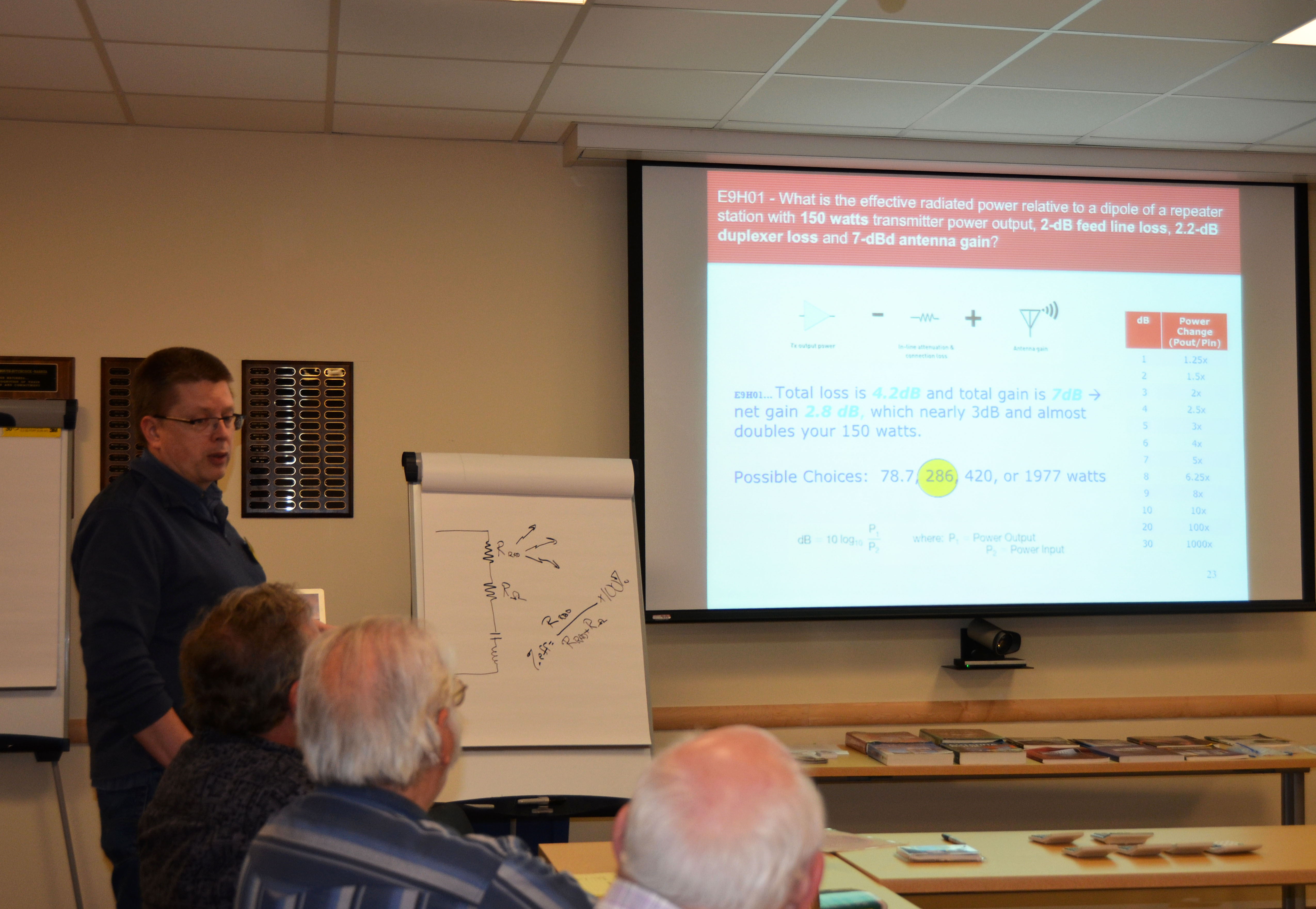
Wayne Wagner Teaching the Extra License Class
Congratulations to all the new Extras!
Bob Bell, KC1FAE
Bernie Biron, K1BFB
Dale Chayes, KB1ZKD
John D’Errico, N1ERF
Bob Fiero, K1WKG
Jamey Finchum, KC1ENX
Greg Fuller, KC1FFQ
Ron Gonzalez, K1LCS
Joe Gordon, KB1RLC
Niece Hayes, KA1ULN
Charlie Pentedemos, KC1EIQ
Brian Quick, W1XMM
Don Risley, KC1CRK
Brian Smigielski, AB1ZO
Bill Warrington, W1TWO
A special thank you to our great instructor and VE team – Wayne Wagner, AG1A, Aron Insinga, W1AKI, Anthony Rizzolo, KC1DXL, Dave Michaels, N1RF, Skip Youngberg, K1NKR, Wayne Grant, KB1HYL, and Fred Kemmerer, AB1OC. Also, an extra special thanks to Merle Insinga, W1MSI, for managing all the logistics and meals on Friday and Saturday!!
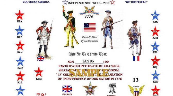
The 13 Colonies Special Event is coming soon. It is the largest on-air special event in the world and it will take place from July 1 (9 AM EST) to July 6th (Midnight EST). The idea of the event is to work each state which grew from the original 13 Colonies. If you work one or more of the 13, you will receive a certificate like the one above. There will also be two bonus stations WM3PEN at Independence Hall in Philadelphia, PA and GB13COL in the United Kingdom. If you work all 13 Colonies plus these, it will be noted on your certificate.
K2K New Hampshire QSL Card
Each Colony station has a K2x Special Event call and will provide a QSL card to confirm your contact. The Event logged over 126,000 contacts in 2015 with K2K New Hampshire contributing over 10,000 of these. You can see a recap of the 2015 K2K New Hampshire operation here.
13 Colonies Special Event 2016 – K2K NH Top Club
I am the Thirteen Colonies State Manager for New Hampshire and we have assembled a team of operators from our club to work the event. Fred, AB1OC and Anita, AB1QB will provide training for the New Hampshire operator team and will make their station available for use during the event.
Our first day in Dayton was spent at Contest University – this was our 5th year in attendance but each year we learn more from the contesting experts. This year, we attended two presentations from Frank Donovan, W3LPL on operating techniques for the declining solar cycle and on 80m and 160m antennas. We also heard a talk from Val NV9L from Ham Nation on Log Analysis tools and another session on SO2R (Single Operator 2 Radio) Operating.
Slide from W3LPL Contest University Presentation
Friday was the first day of the Hamvention and we spent most of the day visiting all the vendor exhibits. We visited the Icom booth, where we looked at the new Icom 7851. It has an incredible display as well as one of the best receivers on the market.
Icom 7851 Display on Large Screen TV
We also saw the new KX2 Transceiver at the Elecraft booth. It is even smaller than the KX3 and is perfect for SOTA and other portable operations. I would expect to hear some NPOTA activations using this radio.
Elecraft KX2 on right, next to a KX3
Friday evening was the Top Band dinner where we learned all about “Top Band Disease” from Larry “Tree” Tyree N6TR. Hams with this disease are nocturnal, love the bottom of the sunspot cycle. They are constantly improving their 160m antennas – when you upgrade your receive antenna, then there are people who can’t hear you, so then you need to improve your transmit antenna – and the cycle continues… The DX Alarm Clock is perfect for those with Top Band Disease!
Top Band Dinner Presentation
After the dinner, we were treated to a concert from the Spurious Emissions Band (N0AX, KX9X, K4RO, W4PA), with hits like “On The Cover of the NCJ” and “Sittin on the Edge of the Band”. They were so funny! You can watch their performances on YouTube http://bit.ly/DaytonSpurs2016.
The Spurious Emissions Band Performs at Dayton
On Saturday, Fred, AB1OC and I presented our Station Building talk to around 250 people as part of the Dayton Contest Forum. It was a great honor to be selected to speak there by Doug Grant K1DG, who has organized the Contest Forum for many years.
Fred, AB1OC, Speaks at the Dayton Contest Forum
We also continued to tour the vendor booths, visiting Club Member Bill Barber, NE1B, at the DMR-MARC booth.
Bill Barber, NE1B at the DMR-MARC Booth
After that, we stopped by Gordon West’s Ham Instructor booth where we spoke to him about the success of the Club’s License classes. Here is a picture of Gordon, WB6NOA, and Fred sharing the secrets of how the Hilbert Transform and the Flux Capacitor make Single Sideband and Time Travel Possible.
Fred, AB1OC with Gordon West, WB6NOA
We also visited the AMSAT booth, where we met Burns Fisher, W2BFJ, who now lives in Brookline, NH and is moving to Hollis. They had a cube sat on display – you can see how small it is below. It’s amazing that AMSAT builds and arranges to launch them into orbit so that we can make QSOs through them!
Anita, AB1QB with a Cube Sat
Fred could not resist a visit to Begali Keys where we purchased a neat travel key. It should be great for operating mobile and for Field Day.
Begali Travel Key
On Sunday, we headed back to New Hampshire, sad that the weekend had come to an end but full of great memories from the trip.
We use cookies to ensure that we give you the best experience on our website. If you continue to use this site we will assume that you are happy with it.