Ever since we built our Mobile HF Station, we’ve talked about taking it to Acadia National Park in Maine and operating from the top of Cadillac Mountain. The 2016 ARRL NPOTA event gave us the motivation to plan the trip for the week before Labor Day. The week before our trip, we saw an article in the ARRL Letter encouraging operation from the newly declared National Monument, Katahdin Woods and Waters in Maine, which had just be designated as NPOTA MN84. Visiting the NPS website, we learned that the park is only a 2 1/2 hour drive from Bar Harbor, where we are staying. We decided to accept the challenge to be the first to activate the new park.

Tuesday, August 30 was our first full day of vacation, we left our hotel room and parked by the Acadia visitor center and called “CQ National Parks”. We ended up with 76 contacts in the log from NP01.
After that we got on the road and headed toward Katahdin Woods and Waters, activating counties along the way including the county line between Penobscot and Aroostook Counties.

As a newly designated National Monument, Katahdin Woods and Waters does not yet have a visitors center or any signs showing you when you enter and exit the park. We just had the map (above) to determine where the park boundaries were. All of the roads in black on the map are gravel roads that are also used for logging trucks.

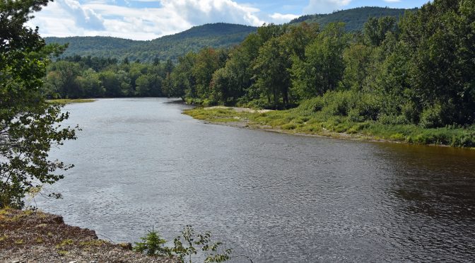
We entered the park from Swift Brook Road off Rt 11 in the lower right corner of the map. We drove through the lower section by the entrance and then headed north along the Eastern Branch of the Penobscot River and operated near the Loos camping area. The sign above confirmed that we were within the park boundaries.

The scenery along the river was beautiful with views of the mountains in the distance.

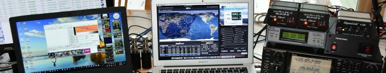
We started operating on 20m and the pileups were huge! Everyone was excited to get this new NPOTA into the log. Fred, AB1OC/M ended up going split on 20m due to the size of the pile-ups. After a while, he moved to 40m to give the close in folks a chance at MN84. We went back and further between 20m and 40m until the pile-ups thinned out. We also made 18 QSOs with the club callsign N1FD to also give the club credit for the activation. We really enjoyed activating the park and the people we talked to were great! We made a total of 350 QSOs from MN84.

We also plan to activate Acadia National Park NP01 again from Cadillac Mountain this week. We will also activate Saint Croix Island, HS01 and Roosevelt Campobello International Park, AA21 in Canada (as AB1OC/VE9 and AB1QB/VE9).
Activating MN84 for the first time was truly a memorable experience. We enjoyed it so much we will be back on Saturday to give more NPOTA chasers a chance at MN84! Hope to talk to you on the air!
Anita, AB1QB