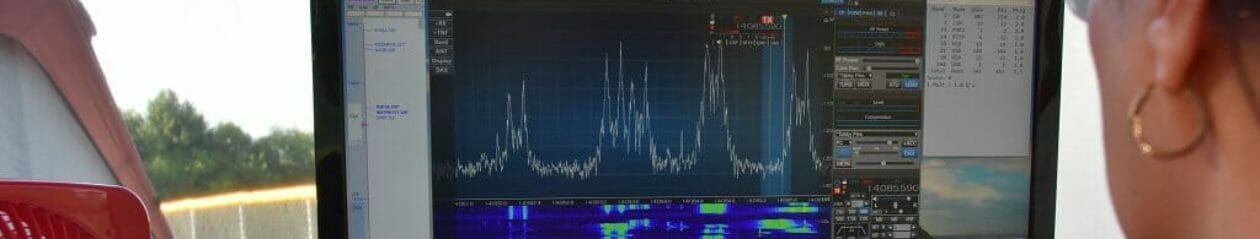
The Nashua Area Radio Society recently held a Tech Night on WSJT-X: FT8, WSPR, MSK144, and More. This Tech Night was recorded and provides a good starting point for folks who want to understand what the WSJT-X software can do, how to use it, and how to integrate it into their station.
August 2018 Tech Night – WSJT-X: FT8, WSPR, MSK144, and More
The video from our Tech Night includes lots of information about how to get started as well as some recorded demonstrations of FT8 and Meteor Scatter contacts.
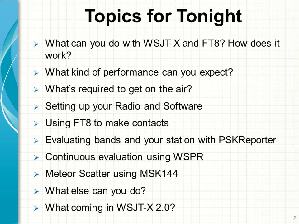
Topics Cover During WSJT-X Tech Night
Our Tech Night also covered tools like PSKreporter and JTAlert that can be used with WSJT-X. Finally, we spent some time on using WSPR to evaluate your station’s performance and how you can use the software to do more “exotic” QSOs such as Meteor Scatter on 6m.
Nashua Area Radio Society members have access to our full library of over 30 Tech Night Video on a wide range of topics for both beginning and advanced Hams. You can see the list of what is available on the Nashua Area Radio Society Tech Night page.
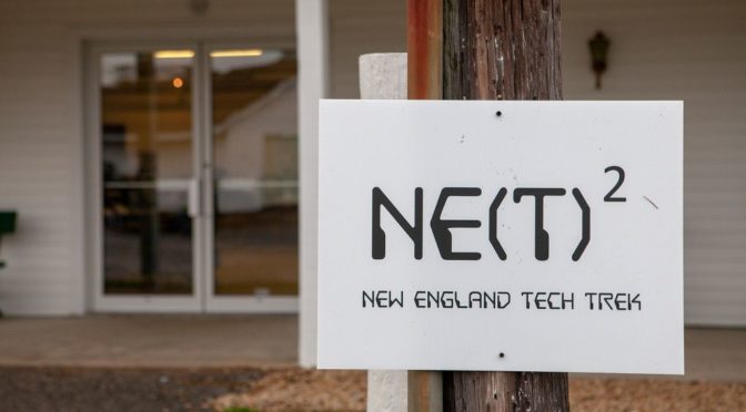
The Nashua Area Radio Society recently hosted another Youth Expo as part of the New England Tech Trek (NETT) at Fall NEAR-Fest. Our display featured many hands-on activities and displays.
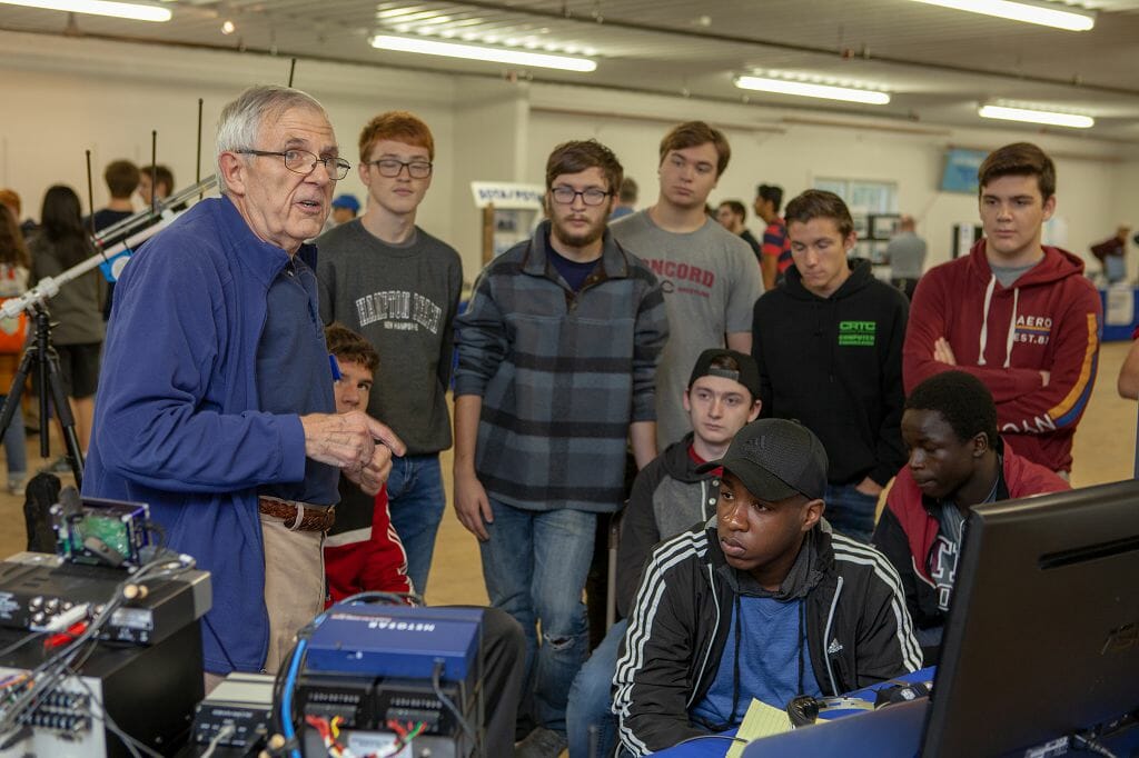
Fred, AB1OC Introduces Students to Amateur Radio in the NETT ClassroomAB1QB Teaching in the NETT Classroom
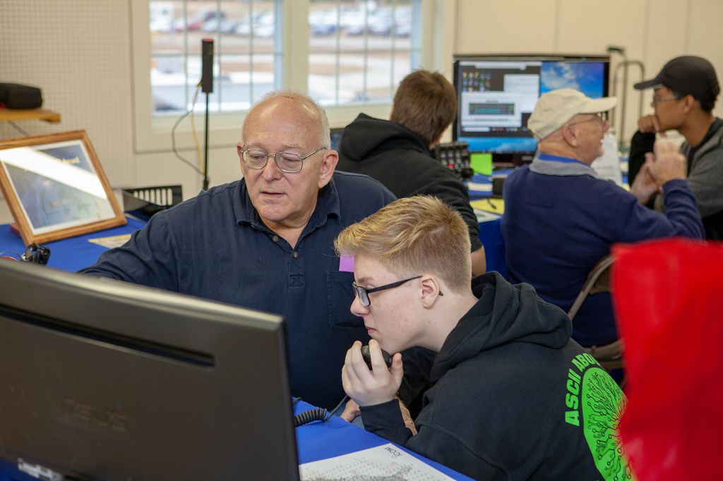
There were quite a few students and teachers who attended NETT on Friday. We had a classroom at NETT to introduce the students to Amateur Radio and the activities in our display.
GOTA and Special Event Stations
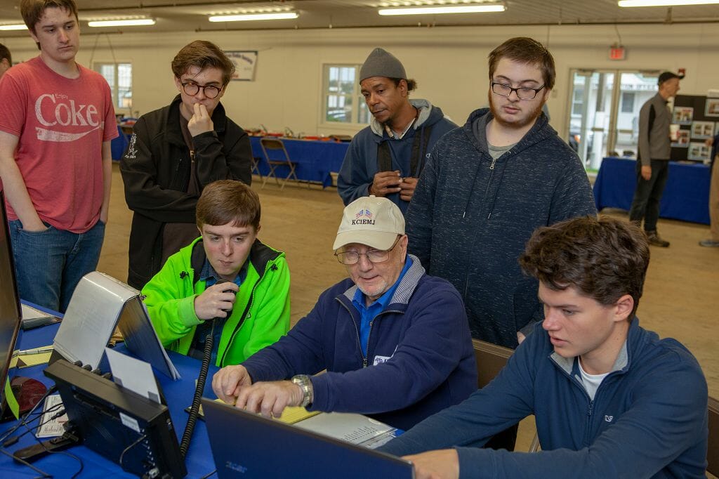
HF GOTA Fun – Ira, KC1EMJ hostingJon, AC1EV Helps a Student Get On The Air
We set up three GOTA stations (two remote HF and one Satellite) at NETT. This gave the students a chance to make some Amateur Radio contacts and experience Amateur Radio at NETT.
N1T Youth Expo Special Event QSL Card
We again hosted an N1T Special Event on the air. All of our GOTA stations used the N1T callsign. Operators and their guests made about 200 contacts as N1T during NEAR-Fest.
Here’s some video from our GOTA operations at NETT.
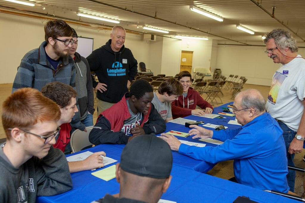
Learning Morse Code
Learning Morse Code at NETT – Mike, Bill, and Jamey are Mentors
Our Morse Code activity at NETT was popular. This gave the students to try out Morse Code and learn from our experts!
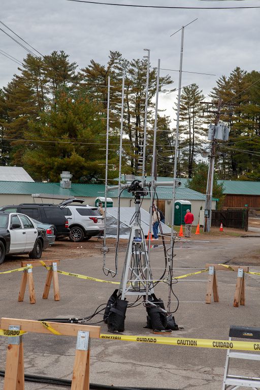
Satellite Operations
Burns WB1FJ Explaining Satellite OperationsSatellite Antennas at NETT
The Portable Satellite Station 3.0 was back again at NETT and Burns, WB1FJ spent quite a bit of time introducing the students and NEAR-Fest attendees to satellites and satellite operating.
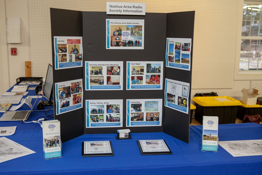
Amateur Radio Displays
NARS Display at NETT
NARS had many displays at NETT and folks who were attended enjoyed learning about many different aspects of Amateur Radio from SOTA, to DXing, to Kits and Computers and more.
Fox Hunting
Jamey, AC1DC hosts a NETT Fox Hunt
Jamey, AC1DC hosted several Fox Hunts at NETT. I ran into several groups of his Fox Hunters throughout the weekend and they were having great fun!
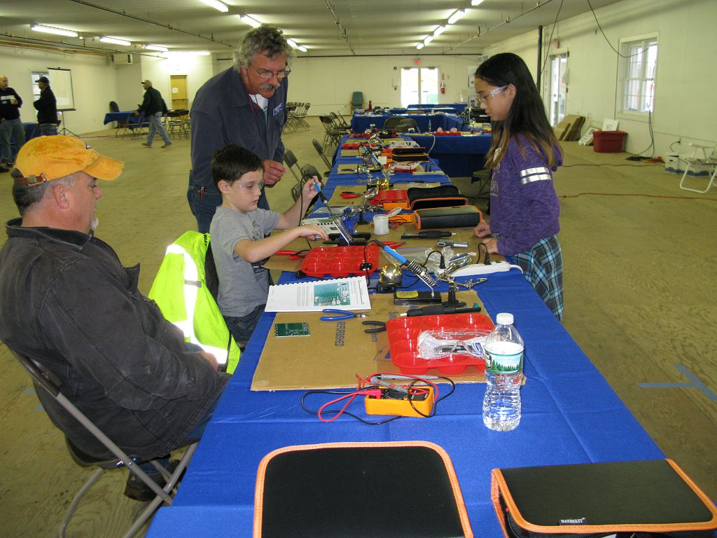
Kit Building
NETT Kit Building – Mackenzie, KE1NZY and Bill, AB1AV MentoringKit Build Fun at NETT – Craig, N1SFT and his Family having kit fun together!
We hosted another kit build at NETT. The latest version of the Morse Tutor kits was available to build at NETT. Over 20 of these kits were built at NEAR-Fest.
Photos and Video from NETT at NEAR-Fest
NETT Signage
NETT Signage
AB1QB Teaching in NETT Classroom
AB1QB Teaching in NETT Classroom
NARS Display at NETT
NARS Display at NETT
NETT Display - SOTA
NETT Display - SOTA
Fred, AB1OC Introduces Students to Amateur Radio in the NETT Classroom
Fred, AB1OC Introduces Students to Amateur Radio in the NETT Classroom
N1T Special Event at NETT
N1T Special Event at NETT
Learning Morse Code at NETT
Learning Morse Code at NETT
Learning Morse Code at NETT - Mike, Bill, and jamey are Mentors
Learning Morse Code at NETT - Mike, Bill, and jamey are Mentors
Morse Code Fun at NETT
Morse Code Fun at NETT
Morse Code Fun at NETT
Morse Code Fun at NETT
NETT Kit Building - Mackenzie,KE1NZY and Bill, AB1AV Mentoring
NETT Kit Building - Mackenzie,KE1NZY and Bill, AB1AV Mentoring
NETT Kit Build - Bill Mentoring
NETT Kit Build - Bill Mentoring
Kit Build Fun at NETT
Kit Build Fun at NETT
Explaining GOTA
Explaining GOTA
John, AC1EV Helps a Student Get On The Air
John, AC1EV Helps a Student Get On The Air
NETT GOTA Ops
NETT GOTA Ops
Jamey, AC1DC hosts a NETT Fox Hunt
Jamey, AC1DC hosts a NETT Fox Hunt
HF GOTA Fun
HF GOTA Fun
Burns Explaining Satellite Station
Burns Explaining Satellite Station
Satellite Antennas
Satellite Antennas
The photo gallery above includes some more photos from NETT at NEAR-Fest.
And here’s a video shot by a NEAR-Fest NETT attendee which include many highlights from NETT.
Thank You To All Who Supported NETT!
The NEAR-Fest organizers, attendees, and several of our members either provided matching contributions or generously donated to our fundraising effort to support STEM learning and skills development through Amateur Radio.
Our NEAR-Fest fund drive resulted in raising $2,400 in the two weeks up to and including NEAR-Fest. Thank you very much to all of our donors!
It would be impossible for us to host one of our Youth Expos without the tremendous support of NARS members. Folks stepped up to provide transportation, display setup, hosting for GOTA and display tours and much more during NEAR-Fest. Thank Youto everyone for your support!
Also, a special Thank You to our Media Committee for providing the photo and video content featured here.
The last full weekend of October kicks off the contesting year for amateur radio. The big one is the CQ WW SSB contest sponsored by CQ Magazine. I’ll cover some basics for this contest along with some strategy and etiquette, and give a preview of what to plan for in November.
CQ WW SSB Contest (00:00Z October 27 to 24:00 October 28)
The CQ WW SSB and CW contests are two of the biggest contests of the year. SSB is always held the last full weekend in October. The CW version of the contest is held a month later (often colliding with the Thanksgiving weekend). Last year over 8600 logs were submitted for the phone contest. That is a target rich environment if you are contesting, or just in the event to get QSOs for chasing awards.
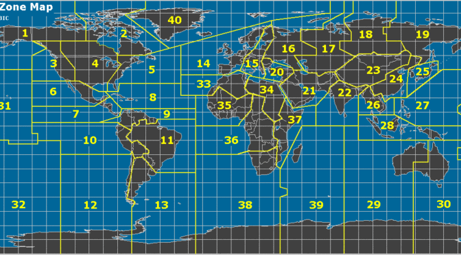
The exchange for the contest is pretty simple: a signal report (always 59) and your CQ Zone (see the map at the top of this post). We’re in zone 5. The Caribbean is in zone 8. Europe is mostly in zones 14 and 15. We hear a lot of Brazil in these contests, too, so expect to hear from zone 11, also.
Guide to the CQ Worldwide DX Contest
With many thousands of hams on the bands, things can get crowded. Here’s what you need to know. The big stations with stacked Yagi arrays, full legal limit (or beyond, as is often alleged), and multiple operators will camp out on frequencies low in the band. They will be loud, and they’ll sit on those frequencies for the whole contest. Unless you’ve got a station like I’ve described (and a small army of volunteers to operate) you can’t compete with that. You can only work them. Remember our two operating styles described in an earlier post? You’ll almost certainly be using search-and-pounce (S&P) to get your QSOs.
Take a moment and look over how the points and multipliers work for this contest. (That’s good advice for any contest!) Points go like this:
Contacts between stations on different continents count three (3) points.
Contacts between stations on the same continent but in different countries count one (1) point. Exception: Contacts between stations in different countries within the North American boundaries count two (2) points.
Contacts between stations in the same country have zero (0) QSO point value, but are permitted for zone or country multiplier credit.
That last bullet point is important. Signals from within the United States will often be the strongest, especially here at the bottom of the solar cycle, but they are worth zero points. As you might imagine, calling a station and asking for a QSO when you offer no points is a tough sell. Don’t call US stations in this contest.
Multipliers are zones and countries (each band counts separately). So, variety is the spice of life — and the secret for success in CQ WW. Try to work as many countries as you can and the zones will almost always take care of themselves.
Here’s my one exception to the “don’t call US stations” guidance above: at the end of a contest, in those last few hours Sunday afternoon, if I’m missing a zone 3, 4, or 5 on a given band, and if I find a US station in that zone, I’ll call them for a “zero pointer” and be sure to say “thanks for the mult.” I only do it if the other station is lonely (has called CQ for a while with no takers). It is a little unsavory, but missing a multiplier that you can hear is awful. In general, you should be able to work Canadian stations for these mults. I call a US station only if all else has failed.
My final suggestion is this: keep calls simple, and the exchange short. You call them, they give you their exchange, and you say only “595”. That’s it. No chit-chat! There are very serious competitors in these contests and every second counts. Be respectful of other people’s time.
November Contests
November is the first full month of the contesting season and there are a couple of good ones on the docket. They are:
I typically take an index card and write out everything above (except the serial number) and tape it to the top of the computer monitor. That way I don’t need to think. All I need to do is read. So, my card has:
___serial___ A NE1RD 02 NH
As with any contest, I’ll suggest to anybody new to listen, listen, listen! Listen to how the exchange sounds. Get a feeling for the rhythm of the QSOs. Once you’ve got it, do a little S&P and get some points.
QSO Parties and other contests
Typically QSO parties run during months without big contests, so there aren’t any in November. But, there are some other international contests that might be fun including:
Ukrainian DX Contest (November 3-4)
10-10 International Fall Contest digital (November 10-11)
OK/OM DX Contest, CW (November 10-11)
LZ DX Contest (November 17-18)
ARRL 160-Meter Contest
For details on these contests, or a complete listing of contests for November (or anytime) see the contestcalendar.com website.
Good Luck
Contesting is a great way to have some fun on the air. You’ll have plenty of people to talk to, and you know the conversation won’t drag! I used many of those contests early in my time as a ham working toward awards like DXCC. You don’t even have to submit your log to the contest sponsor if you don’t want to. Just get on and have fun. Good luck and 73 de NE1RD.
Radio Amateurs Developing Skills Worldwide
We use cookies to ensure that we give you the best experience on our website. If you continue to use this site we will assume that you are happy with it.