We have just received word from our ARISS Mentor, Dave Jordan, AA4KN – Our ISS Crew Contact will take place on Friday, December 7th at approximately 1:45 pm EST. Activities on-site will begin with some videos and station tours before the contact.
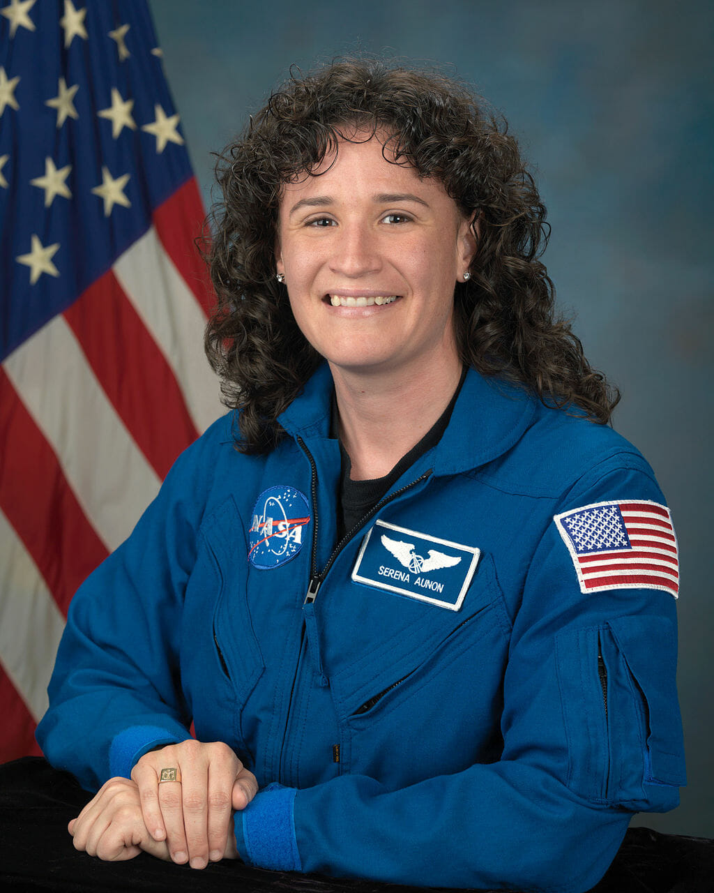
Serena Aunon-Chancellor – NASA Astronaut
We will be using the Nashua Area Radio Society callsign, N1FD, for our contact with NA1SS. We believe that our contact will be with Serena Aunon-Chancellor, KG5TMT. We are all very, very excited to hear the news!
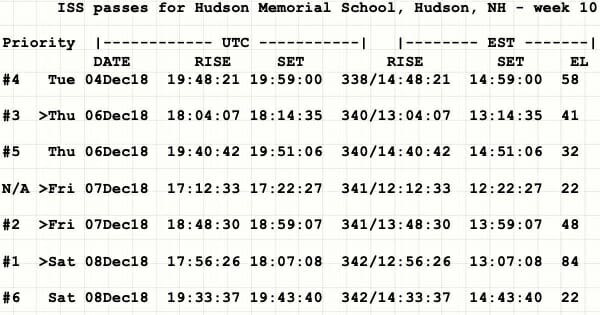
Prioritized ISS Passes for our Crew Contact
This date/time was our second choice and the ISS will be on a good pass reaching a maximum elevation of 48 degrees at Time of Closest Approach (TCA). Our contact with the ISS will last about 10 minutes.
We are just awaiting notification of the final date and time for our contact and we’ll begin final setup and testing at HMS.
We’ve been sharing our progress as we’ve on the Nashua Area Radio Society’s Youth Forum as we have worked through our final preparations. I also would like to share a summary here along with some insights on what we’ve learned along the way.
An ISS Crew Contact is No Small Undertaking …
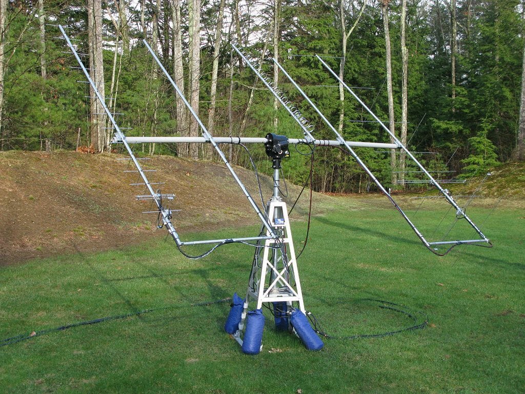
ISS Antenna System Test
We have been working for almost a year now to get ready for our contact. We’ve built and tested two space ground stations and we’ve discovered and addressed several performance and reliability issues with these stations during trial deployments at Field Day, Ham Fests, License Classes, and during testing here at our QTH.
Leading the ARISS Crew Contact Application Process for our contact
Integration of Radio Space Science concepts into their student curriculum
A Skype contact with a NASA Engineer
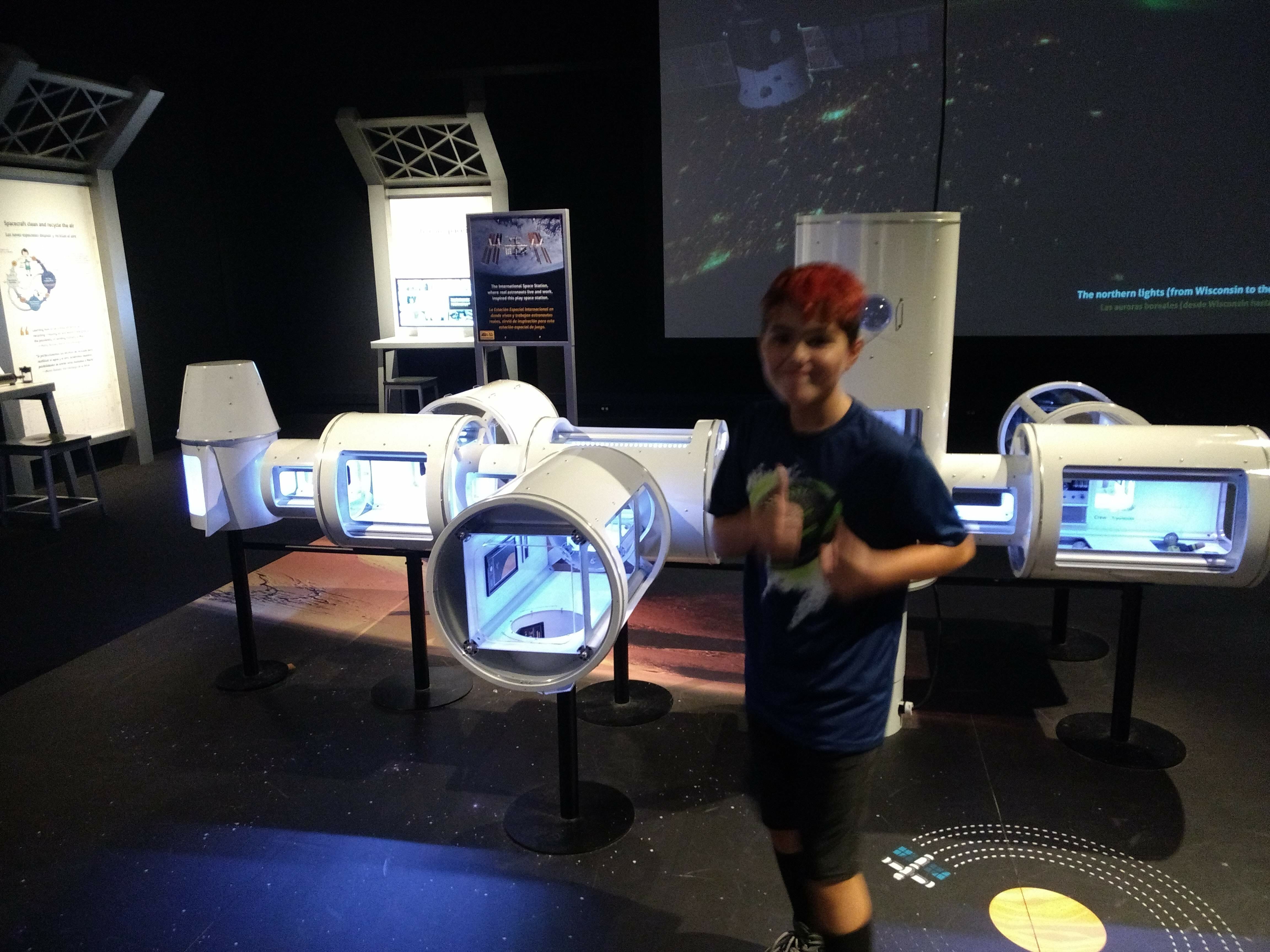
Visiting the Boston Museum of Science special exhibit on Space and the International Space Station
A High Altitude Balloon Project with the Nashua Area Radio Society to learn about Atmospheric Science and Space Communications
Space-related student projects including building rovers, participating in an egg drop, and having their pre-engineering program students work on solutions for the ISS
Holding a Field Astronomy and STEM night for students and building Amateur Radio into the school’s annual STEM Nights
Audio-Visual Elements are Important and as Challenging as the Ground Station Equipment…
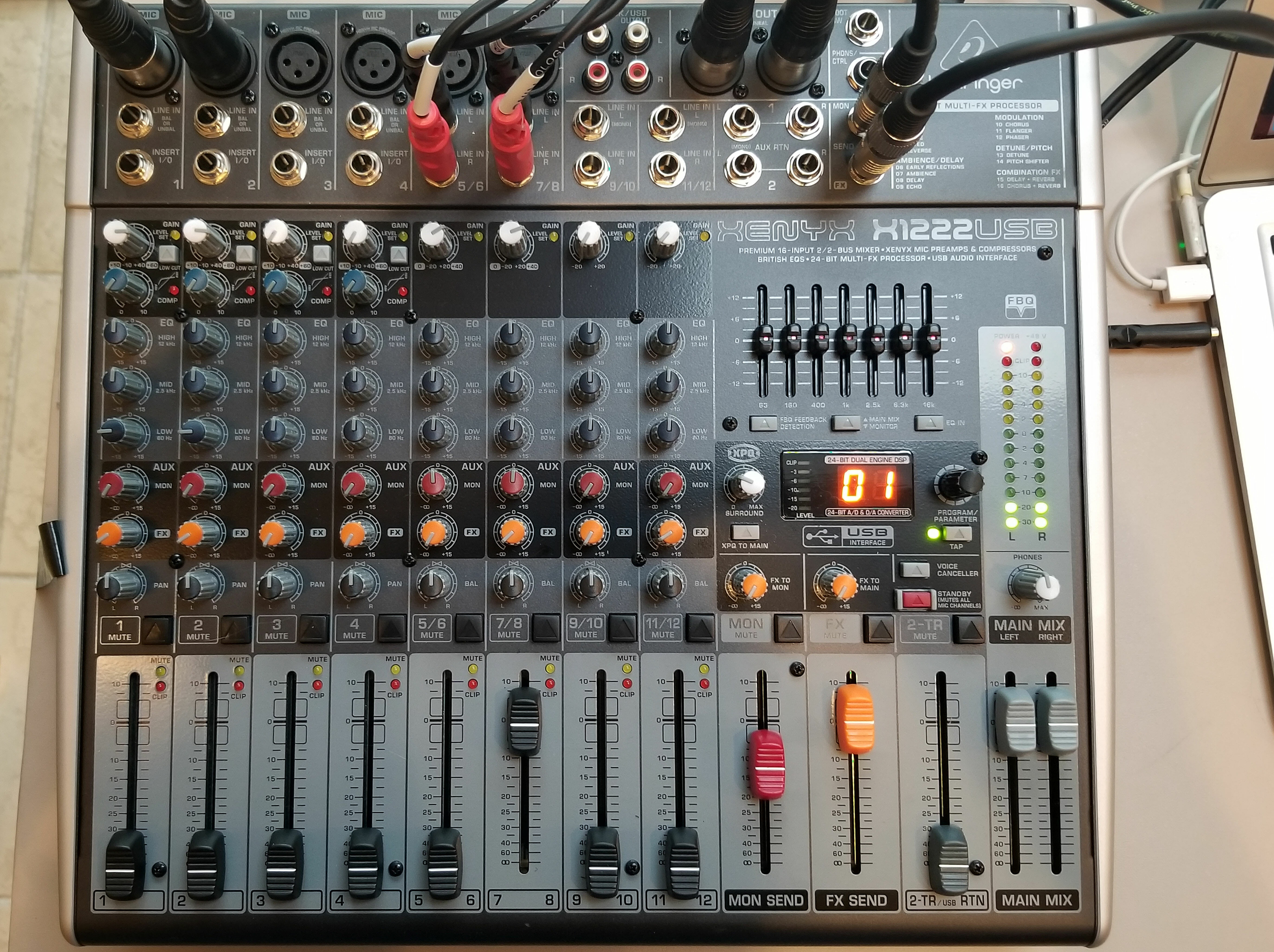
Sound System Mixer
We planned from the very start to provide a shared, multimedia experience as part of our contact. Our plans included:
Providing a professional-quality audio and video experience for the students, parents, and faculty members at HMS during our contact
Creating a high-quality Video Capture of our Contact
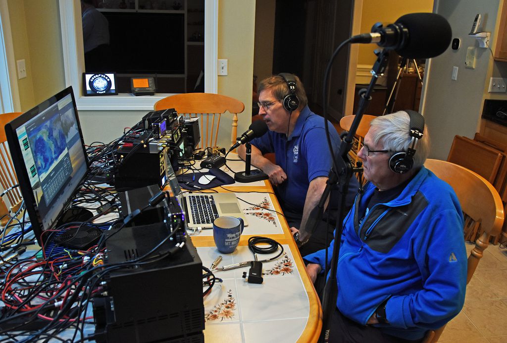
Dave, K1DLM who is a member of NARS had extensive professional sound experience and was able to help us with this part of our project.
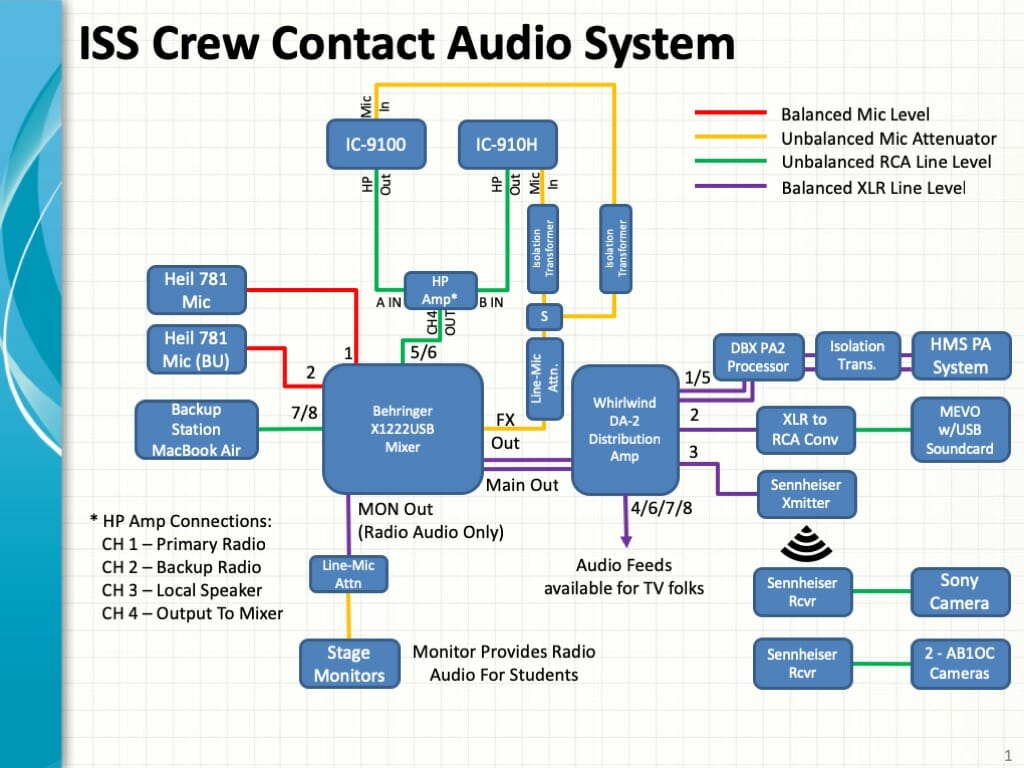
Audio System for ISS Contact
Dave put together a professional-level A-V system design to support our contact and provided much of the gear to realize the design. His uses a pair of communications microphones, a pro-mixer, and audio interface gear to provide student and radio audio to the sound system in the auditorium at HMS as well as to an array of video cameras. The system makes extensive use of XLR cabling and pro-level devices to ensure clean audio.
Video Presence on the Internet is an Important Element to Draw Interest in a Project Such as Ours…
We Live Streamed some of our Station Testing activities to Facebook and we were amazed at the interest and response that we received. Many folks worldwide followed our progress on Facebook in real-time as we set up and completed our full station test.
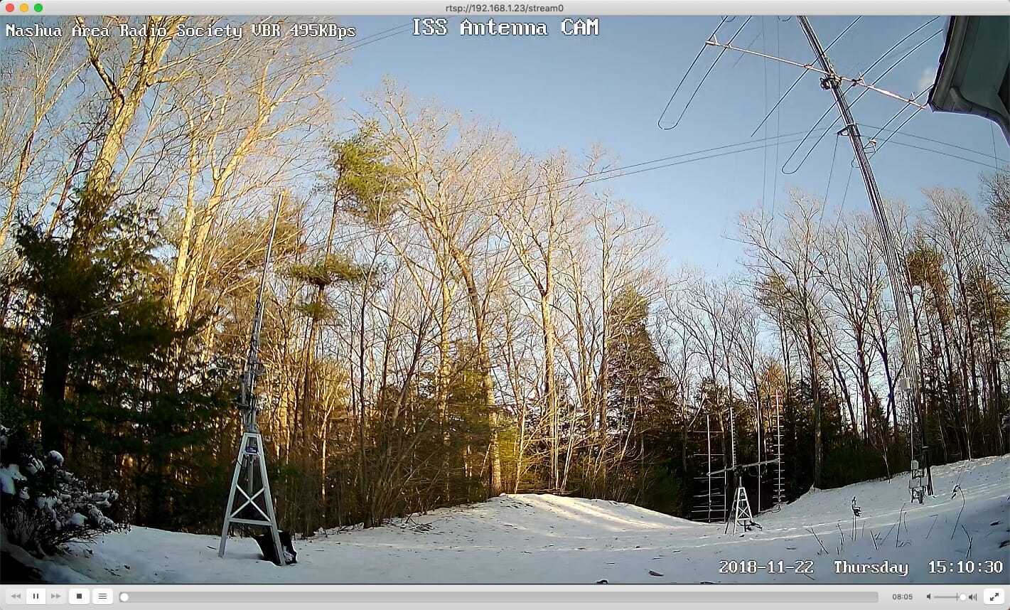
ISS Antenna Camera Test
We are planning to have two IP Video Cameras Live Streaming to Facebook during our contact. One in the room to provide video of the students as they talk with the astronaut on the ISS and a second on our antennas as they track the ISS.
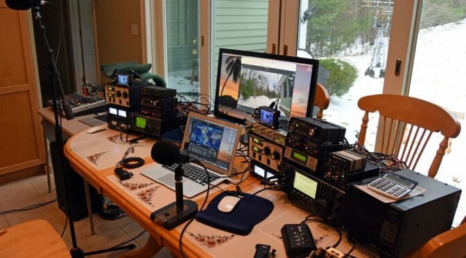
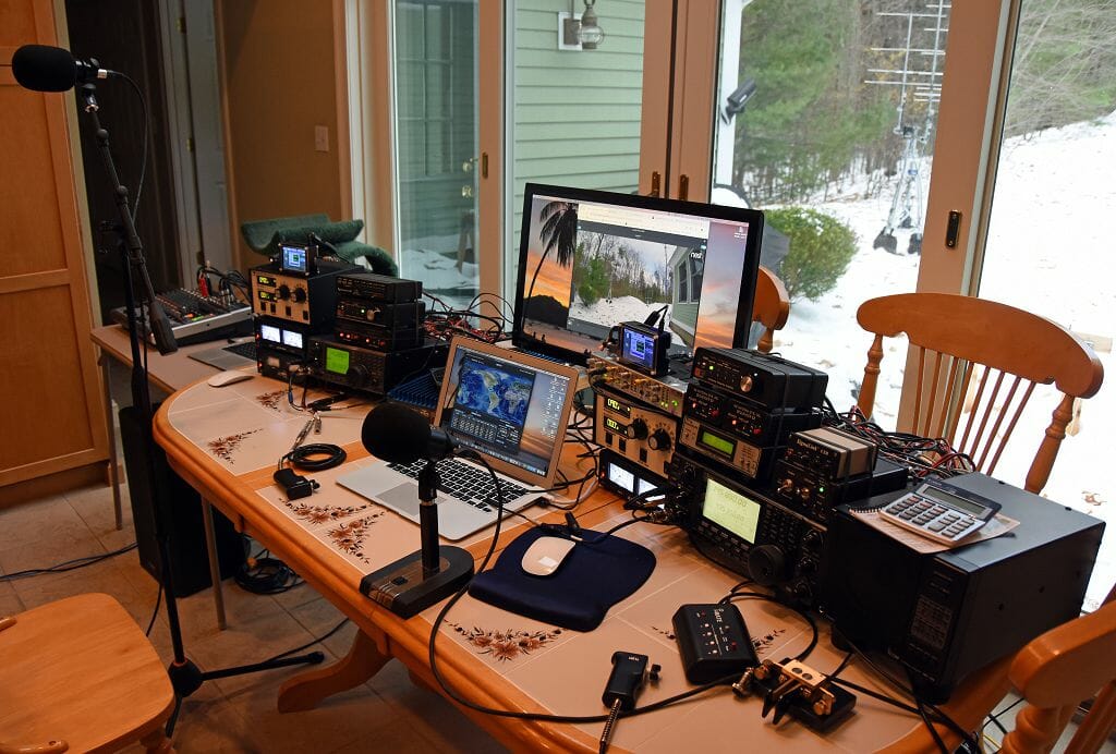
Its Critically Important to Test the Complete Station Ahead Of Time – New Challenges Emerged when we Mixed Audio and Radio Gear…
Full Station Setup and Test
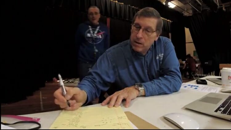
We set up the full station (Primary and Backup) along with all of the Audio and Video Gear about 3 weeks prior to our contact for a complete system test. We learned a great deal in doing this and we encountered several problems which we have since corrected.
On-Air Station Test
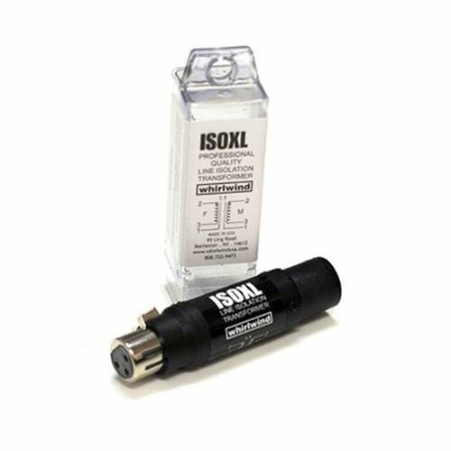
The most important issues did not show themselves until we made some contacts with all of the A-V gear in place. We had problems with RF aggravated ground loops in the radio microphone circuits during the initial test. These problems did not show themselves until we added the audio mixer and sound system into the station.
Audio Isolation Transformer
These problems were easily corrected by adding Audio Isolation Transformers into the radio microphone circuits.
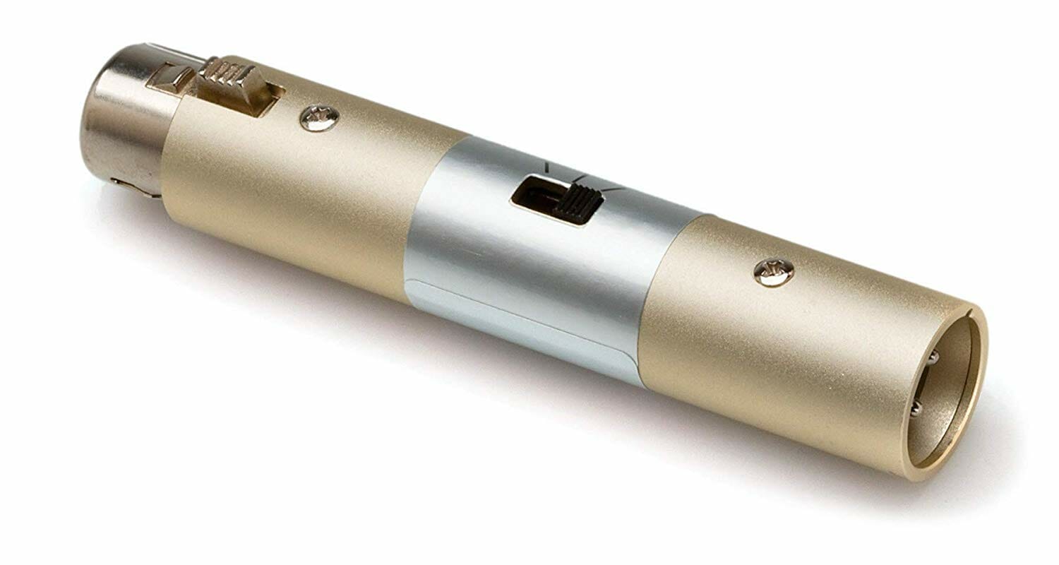
XLR Line to Microphone Level Attenuator
We also solved some potential issues related to level differences between line and microphone audio circuits using Audio Attenuators.
These problems were not difficult to solve but they would have seriously degraded our contact if we had not discovered them early while there was still plenty of time to secure parts and retest.
Data Networks in Schools and Public Places Require Configuration Adjustments to Support Contact Elements…
Data Network Test at HMS
Schools and other public places typically do a good job of protecting their data networks and users from threats from both the Internet and within the venue. Tracking Programs, IP Cameras for Live Streaming, and other contact support gear are not typical devices that would be in operation on such networks. Also, many public venues rely almost exclusively on WiFi for access to the Internet and typically prohibit or severely limit client devices from communicating with each other.
WiFi can often suffer from RF interference issues when many devices like Smart Phones are located together in a small area. This situation is common in large gatherings.
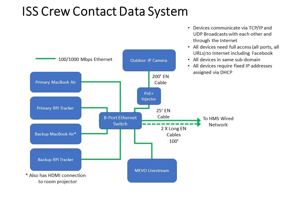
Data System for ISS Contact
We had quite a bit of experience with these problems as part of other school projects we’ve done. Our approach is to use a wired network with a local Ethernet switch for communications between the elements in our stations.
The HMS IT team at configured their network to fix the IP addresses of our devices. They also adjust their firewall rules so that our devices have the required access to the Internet. The IP cameras where the most challenging elements here.
Packed and Ready to Go…
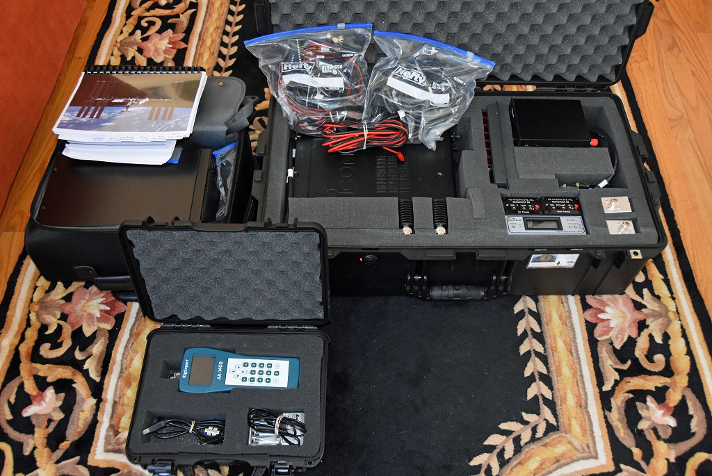
Equipment Packing and Protection
Well, all of our gear is packed and ready to go for setup on-site at HMS. The next article in this series will cover the on-site set up for our contact.
A number of people have had difficulty setting up their radios using the USB interface for WSJT-X and FT-8. It helps to have a basic understanding of the computer interface within the radio. The good news is Kenwood, Icom, Yaesu and even SignaLink share a similar architecture, often down to the same device part numbers and software drivers.
Once the USB cable is connected to the radio the first device in the data path is a USB Hub. Just like a Hub, you might use on your desk its function is to provide multiple USB ports with only one cable from the PC or Laptop. It does not require configuration or drivers and is transparent to the user.
There are two devices connected to the Hub inside the radio. They are a USB UART Bridge and an audio CODEC. If there wasn’t an internal Hub each of these devices would have a separate USB cable to the PC. This is important as it shows how separate and independent they are when setup, access, and drivers are considered.
Kenwood, Icom, and Yaesu use a USB UART Bridge from the SiLabs CP210X family. (SignaLink does not have a serial CAT interface). All three plus SignaLink use a USB/CODEC from the Ti PCM290XB family.
We will review the functions and setup of the USB UART Bridge first.
USB UART Bridge
A “Bridge” may sound complicated but all this device does is accept bi-directional USB and produces bi-directional serial data. It is a bridge between USB and serial data.
You may have used an adapter with a USB connector on one side and a DB-9 9 pin serial connector on the other side. It is likely it used the Silabs CP2101 or a similar device made by FTDI. This interface is often referred to as a Virtual Com Port (VCP) which replaced “real” DB-9 Com ports found on computers into the 1990s. It is called virtual because much of the serial COM port functionality is achieved with software.
The radios that can be computer controlled have a CAT interface (computer-aided transceiver). A related term is CI-V (Communication Interface v5) which is an Icom standard that defines the messages the radio will respond to. The messages are in text (ASCII) format, for example, to transmit you would write TX; to the radio. With a serial interface or VCP, you can send ASCII text messages to your radio using Hyperterminal or an application called PuTTY and it will respond.
Older radios used a CAT interface that required a serial COM Port on the PC. Most of the current radios can still accept serial data through an ACC (accessory port), and a few still have a DB-9 9 pin connector for serial data. Newer radios also have a USB interface and use the USB UART Bridge to receive the serial CAT/CI-V messages from the PC. A radio menu setting is used to select data over an ACC or the USB for radio control.
Audio is not passed using the USB UART Bridge CAT/CI-V interface, it is strictly used for radio commands.
WSJT-X uses a small set of messages over the CAT interface to control the radio. These include band changing, VFO frequency, PTT and a few others.
The USB UART Bridge requires a VCP driver that must be installed by you before connecting the radio to the PC. If you connect the USB cable before installing the driver Windows may locate and install a driver, this works less often than auto-correct in spell check. Once the wrong driver is installed it can be very difficult to uninstall. The correct driver can be downloaded from the radio manufacture’s website.
Once the driver is properly installed and the radio connected the driver can be found in the Windows Device Manager as shown in Figure 1. Note the COM Port number, you will need it to configure WSJT-X. Your COM port number will probably be different.
Figure 1 USB UART Bridge Driver
By right clicking on the driver and selecting properties and then the Ports tab you can set the Baud rate, Parity, Stop Bits, and flow control as seen in Figure 2.
Figure 2 USB UART Bridge Settings must be the same in Device Manager and WSJT-X
Typical settings are as follows:
Baud Rate: 9,600 (Standard values from 9,600 to 115,200 can be used)
Parity: none
Stop Bits: 1 (7300 or 590S/SG 1 or 2 can be used, older rigs and SignaLink with a CP2101 must use 1)
Flow control: Hardware
The settings you select in Device Manager Properties must be used in the WSJT-X setup.
Once these settings are set for the COM port and in the WSJT-X app consider them set, and leave them. If you have completed these steps and do not have CAT/CI-V control of the radio it is due to incorrect radio settings, a bad/cheap cable, you are connected through an unpowered Hub, or are using the front panel USB port of a PC. (Front panel USBs are hit and miss).
Yaesu radios have an additional USB UART Bridge accessible through the hub. You will see an Enhanced port for CAT and a Standard port for PTT in Device Manager. Each has a unique COM port number. WSJT-X has a spot for a second COM address in Settings/Radio for “PTT Method”. The Standard port COM address and RTS is entered for PTT Method. I have used these setting for an FT-991 and FTDX-3000.
CAT is selected for PTT for Icom and Kenwood radios, a second COM address is not used.
USB (AUDIO CODEC)
The second device on the Hub’s output is a CODEC. The CODEC decodes the digitized audio on the USB to analog using an ADC, and using a DAC the analog audio from the radio is digitally coded to be sent to the PC over the USB. Taken together with CODEC COdes and DECodes audio signals from a digital format.
There are no COM port addresses, baud rates, stop bits, etc for you to set since it is not a VCP, it is a standard USB interface.
A PCM290x CODEC is used in the IC-7300, TS-590S/SG, FT-991, SignaLink, and others. The driver is included with Windows XP through 10 so there is nothing for the user to install. Once the CODEC has a USB connection and power it will automatically be installed and set up. The CODEC will appear in Windows Device Manager under “Sounds, Video, Game Controller” when power is applied to the radio. It can be seen in Figure 3 as “USB Audio CODEC”. If there is more than one and you are not sure which one is the radio’s disconnect the USB cable and see which one disappears and then reappears when reconnected.
Figure 3 “USB Audio CODEC” in Device Manager and WSJT-X
If the driver has been used with multiple radios it may appear as “3-USB Audio CODEC” or similar which is not a problem provided the same exact label as seen in Device Manager appears in WSJT-X and the Windows Sound settings.
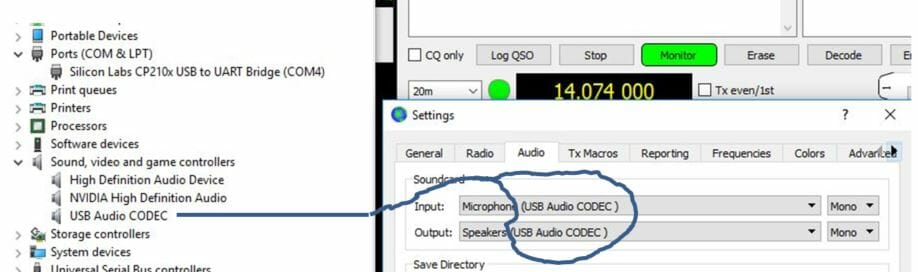
The audio CODEC was identified as “USB Audio CODEC” in the device manager, WSJT-X, and was the selected Input and Output device in the Windows Sound Setting as seen in Figure 4.
Note: The label “microphone” has been replaced with “Line” for PCM290XC rev C CODECs used in the TS-890, other recently released radios, and when a CODEC is replaced due to failure.
Figure 4 Windows Sound Manager
Summary
Knowing there is a Hub and two independent USB devices in the radio should help when setting up a radio for WSJT-X. The first device is a USB to Serial converter supporting CAT/CI-V, the second device is a USB to Audio CODEC supporting audio input and output.
You will not resolve audio issues by changing the USB UART Bridge settings for baud rate or the number of stop bits. Similarly changing the audio I/O devices is not going to solve a CAT/CI-V problem.
I was surprised to learn the driver we install is only a generic USB UART Bridge. I expected a large complex proprietary composite driver that handled the CAT/CI-V and the audio CODEC. The audio CODEC driver is a standard Windows product.
I have identified the various switches on the radio’s circuit boards and their related menu functions. An example is the switch and menu item that connects the audio I/O from the radio’s processor to the ACC port, Microphone, or the CODEC. I plan to do a separate article on this topic.
In the interim knowing, there are two independent devices should help demystify the menu settings a bit. Baud rate, USB for CI-V, Echo on, etc are for the CAT using the SiLabs USB UART Bridge. Audio I/O levels, Modulation source, and related options only apply to the USB CODEC.
This article may seem a bit bottoms up. It was written from the vantage point gained while troubleshooting and then replacing Hubs, bridges, CODECs and surrounding devices in numerous radios. USB is the most fragile interface on the radio when lightning is a factor….these are the parts at the end of the USB cable.
Radio Amateurs Developing Skills Worldwide
We use cookies to ensure that we give you the best experience on our website. If you continue to use this site we will assume that you are happy with it.