The CQ Worldwide DX SSB Contest has just completed and we made a big step toward our goal of earning an ARRL DXCC Award for our club call, N1FD.

The following club members operated as N1FD in the contest:
- Abby Finchum, KC1FFX
- Connor Finchum, KC1GGX
- Jamey Finchum, KC1ENX
- Mike Rush, KU1V
- Joe Gordon, KB1RLC
- Mike Struzik, AB1YK
- Fred Kemmerer, AB1OC
- Anita Kemmerer, AB1QB
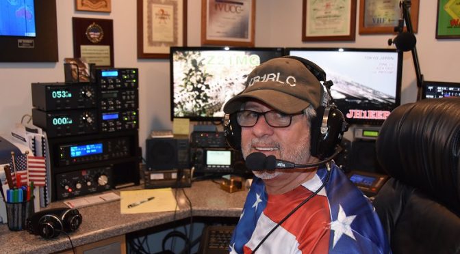
The N1FD Team operated from our station (AB1QB/AB1OC).

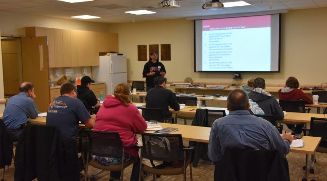
Many of the club members who joined us had not previously had the opportunity to operate in a major DX contest. Our approach to the contest included a significant amount of time spent to help folks learn how to operate in a major DX contest such as CQ WW DX. All of the members of the N1FD Operator Team did a great job and we worked a lot of DX given the relatively poor band conditions throughout the contest period.
")
We entered the contest as N1FD in the Multi-Op, One Transmitter category and we operated in the High Power, Assisted class. This category allowed us to have two transmitters on the air on different bands simultaneously. One transmitter was the “run” station from which we could call CQ and contact any new callsigns on a given band. The other transmitter was a multiplier only station which was only allowed to work new multipliers (new DXCCs and CQ Zones) on a given band. We had both stations on the air simultaneously for a good portion of the contest period.

We operated on all of the contest bands from 160m through 10m during the contest. We mostly operated in Search and Pounce mode to focus on maximizing the number of DXCCs and CQ Zones worked. Search and Pounce mode also made it easier for the less experienced folks on our team to learn about contesting. We used a mix of data from the spotting cluster and tuning the bands to find and work stations. We did a bit of operating in Run mode (calling CQ) as well to help put additional QSOs in our log to boost our final score and to learn how to operate by calling CQ in a contest.

We used the N1MM+ logger in a multi-op, networked configuration during the contest. This allowed us to share a single log between our two stations and to keep track of the multipliers (DXCCs and CQ Zones) that the combination of the two stations worked during the contest.

We worked a total of 108 countries in the contest and brought the total DXCCs worked by the N1FD callsign to 121. This means that we worked a complete DXCC during a single weekend! We added 40 new DXCCs worked as a result of our contest operation. Before the contest, our club call had 62 confirmed countries. We will need 38 more confirmations to qualify for the ARRL DXCC Award. We have received a total of 16 of the needed 38 new DXCC confirmations via LoTW as of the end of today!
We also gave our club a good start toward earning future 5-Band DXCC and DXCC Challenge Awards as we worked a total of 283 band-points during the contest.

We also made progress toward earning our CQ WAZ (Worked All CQ Zones) Award – we now have 33 our of 40 zones worked and 28 confirmed.

We made a total of 607 QSOs during the contest for a claimed score of 588,208. The actual score may be lower than this after the contest adjudication process completes in several months as deductions will be taken for any incorrect calls or exchanges. You can also see our results at the 3830 Score Rumor website.

Everyone involved had a lot of fun and learned some new skills. We are thinking about operating again as N1FD in the ARRL Sweepstakes Contest in November (Nov. 19-21). Please let us know if you’d be interested in joining the N1FD Team for this contest.
73,


")