Introduction
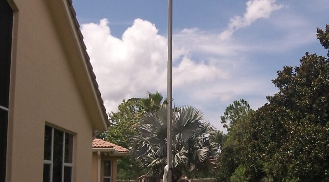
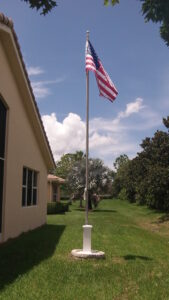
A flagpole antenna has been fabricated that can be installed in any residential setting. The fiberglass tubing has been designed with a pair of 2′-long coupling sleeves so that the entire tubing assembly will separate into 3 sections. The flagpole has been designed to contain a 6-BTV vertical [1], including an 80m resonator and stinger. When equipped with the 80m resonator and stinger, the entire flagpole stands 25′ high. The flagpole is painted with Marine Epoxy finish [2] to preserve the fiberglass. The tilt-over mechanism [3] for the 6-BTV is contained within a white deck post sleeve [4]. A remote tuner [5] and common mode choke is concealed within a white circular pallet that has been fabricated from PVC trim lumber. The pallet also conceals the radial plate [6]. A standard flag pole truck [7] with a finial ball [8] caps the tubing for a finished appearance.
Flagpole Antenna Construction Details
Concrete Pour, Radial Plate, 6-BTV Concealment, and Common Mode Current Suppression
The concrete has been poured, and a radial plate [9] installed for a 6-BTV [10] Vertical Antenna. The foundation for the 6-BTV is an 8” DIA x 4’-0” long concrete form tube [11]. A 1-1/2″ OD seamless stainless tube [12] was embedded in the concrete for attachment of the 6-BTV. A pipe or tube no larger than 1-1/2″ OD must be used, if the entire tilt-over assembly is to fit within an 8″x 8″ deck post sleeve. A total of 60 radials [13] were bolted to the radial plate [14], Figure 1. These vary in length from 35 ft (10.67m) to 8.5 ft (2.59m). The radials are anchored with 6″ x 11 gauge landscape staples [15]. In one week, the radials were nearly concealed by the lawn. The 6-BTV is concealed within 2.5″ OD, 2.26″ ID, fiberglass tubing [16]. The tubing was joined with short sleeves of 2.75″ OD, 2.51″ ID, and fiberglass tubing [17]. A 1-1/2″ (38.1mm) PVC electrical conduit [18] is also visible on the far left. It is used to carry 75 ft (21.9m) of DX Engineering DXE-400MAXDX075 [19] from the service entrance to the antenna. A common mode choke [20] was placed right at the antenna to suppress common mode currents on the coax shield.
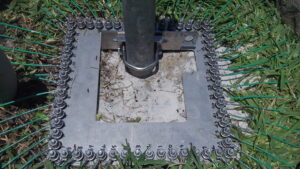
Figure 1. DX Engineering Radial Plate. Sixty ground radials are visible. Each bolt has been double-nutted so that the radials may be disconnected without lifting the ground plate. In order to save time, each of the 60 radials was prefabricated to the plot plan to fit the available space.
Figure 2 shows the brick border [21] that was added to the radial plate installation. It serves to protect the antenna, radials, and conduit from the lawn mower. It also serves to hide the lawn that is close to the radial plate. As the radials converge on the radial plate, there is considerable lawn die-off. Once this patch of lawn is covered with a tree ring landscape apron [22] as pictured in Figure 3 and a decorative pallet, it is no longer visible.
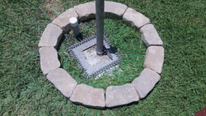
Figure 2. Brick Border. The border provides a convenient way to protect the radial connections and radial plate while mowing. The underground conduit is also visible.
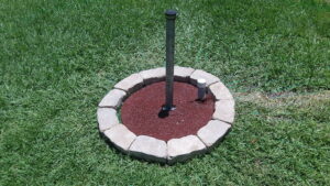
Figure 3. Landscape Apron. A landscape apron was installed over the radial plate to retard the growth of grass and weeds. The mounting pipe length was shortened. The underground electrical conduit that carries coax and the antenna tuner control cable is visible.
Fiberglass Tubing
A 25′ tall fiberglass flagpole has been constructed that will conceal a 6-BTV vertical antenna. A picture of the sections, as constructed, is provided in Figure 4. In order to clear the aviation hose clamps that clamp the 6-BTV aluminum tubing and resonators together, as well as the 80m coil, a pole has been fabricated from 2-1/2″ OD fiberglass tubing [23] obtained from DX Engineering [24]. The sections may be separated for storage during high winds, and these sections have been coupled together with sleeves constructed from 2-3/4″ OD x 24″-long fiberglass tubing [25] also obtained from DXE. The three sections measure, from foreground to background: Bottom: 8′ (96″), Middle: 12′ (144″), Top: 8′ (96″).
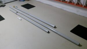
Figure 4. Fiberglass Tubing Sections. Sections of tubing are bonded together with non-corrosive RTV. If bonding is performed as shown, the assembly will spill water, once assembled. See text.
Once assembled with overlap, the overall length is 25′ long not including the flagpole truck [26] and finial ball [27]. It is anticipated that an additional 1′ of 2-1/2″ OD tubing may be removed just below the truck/ball, and this will reduce the bending moment. The fiberglass dielectric was expected to change the antenna tuning but it turned out to be negligible. The proximity of the truck and ball to the 80m “stinger” resonator was evaluated in its present configuration, and its effect was negligible.
Note that it is essential that the DX Engineering DXE-RLT Reinforced Lower Tube [28] manufactured for the BTV antenna series be utilized in order to support the additional bending moment of the flagpole.
Use Without 80m Resonator
If 80m operation is not required, the top 2-1/2” OD fiberglass tubing may be omitted. Only the bottom two sections need to be fabricated. The flagpole truck and finial ball are moved down by one section without modification to the design.
Fiberglass Tub
ing Fabrication
The following steps were performed outdoors using personal safety equipment (PSE) consisting of a 3M fine particle respirator [29], safety goggles and gloves. If the flagpole is to be painted, a suitable respirator designed specifically for the constituent paint volatiles must be employed in a well-ventilated area, preferably outdoors.
The tubing sections are cut using a straightforward technique. First, the pieces of tubing being cut are wrapped circumferentially, under the cut-line, with ordinary masking tape and the desired lengths are marked circumferentially with dots from an indelible marker. The tubing is placed on a set of V-blocks, Figure 5, that come as an accessory to a set of Stanley collapsible sawhorses [30]. The V-blocks slip onto the ends of the sawhorse.
The tubing is rotated in the V-blocks and gently scored on the dots with a small reciprocating saw [31] that holds a Lenox 8″ Diamond Blade, P/N 800RDG [32]. Once the circumference is scored, the tubing is rotated while applying constant pressure to the reciprocating saw to complete the cut all the way through. If care is taken, the fiberglass cut will be clean and straight, and there will be minimal fraying of the glass fiber. The masking tape is removed, and the cut is gently finished with plumber’s grit roll [33] or emery cloth.
The adhesive chosen for assembly is Loctite SI 5011 CL Non-Corrosive RTV [34], also known as “ULTRAFLEX”. This is a neutral cure adhesive/sealant that cures by emitting non-corrosive methanol. It takes some additional time to cure, but it is worth it.
Corrosive silicone adhesives continue to cure over a long period by absorbing water and emitting acetic acid. It is a good idea to avoid using them.
Loctite SI 5011 CL adhesive comes in a caulking tube, and this project will consume over half a tube. The pieces of tubing can be wrapped with masking tape so that when the tubing is assembled and the excess adhesive is removed, a clean adhesive line can be obtained.
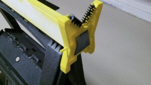
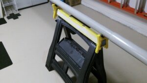
Figure 5. Sawhorse V-Blocks. (Top) The V-Blocks slide onto each end of the expanding top rail of the sawhorse. (Bottom) The V-Blocks are used to rotate the fiberglass tubing while it is being cut with a diamond reciprocating saw blade. Rotating the work results in a square cut. See text.
Please spend some time studying the photograph, Figure 4, and the assembly sketch, Figure 6, so that the adhesive is applied in the correct places. This will ensure that the assembly will shed water and slide apart.
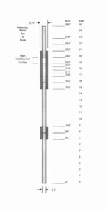
Figure 6. Fiberglass Tubing Assembly Drawing. The adhesive is applied to the 3 larger diameter sleeves so that the sections will disassemble into 3 pieces. Please study the drawing at the 204″ mark. You will see where two of the outer sleeves touch. When assembled, the sleeves will spill water. In the final version, the 80m resonator and top tubing were removed. See text.
Once the tubing is correctly joined, the flagpole will come apart, as shown in the photo. Please note that the assembly sketch is just that – a sketch – it’s not to scale. The white gap that is visible in the upper section is an air gap for the 80m coil. It provides some additional airflow around the coil. The adhesive is applied in a number of long stripes along the 2-1/2″ OD tubing. The 2-1/2″ OD tubing is then slowly rotated within the 2-3/4″ OD sleeving until the adhesive is spread uniformly between the tubes being joined, and the correct overlap is obtained, as is shown in the photograph, Figure 4, and assembly sketch, Figure 6.
Excess adhesive is removed with a paper towel or cloth. Care is taken to provide a continuous bead of adhesive around each joint so that each joint is waterproof. Once the adhesive is dry, the masking tape is removed. The flagpole is assembled with adhesive so that all of the sleeves “spill water”, i.e., water does not enter the sleeves. This makes tubing disassembly easy once the flagpole antenna is tilted on its OMNI-TILT mount [35].
Flagpole Truck, Finial, Halyard, and Cleat
A standard 2-1/2″ flagpole truck [36] and decorative finial ball [37], visible in the title photo, finishes the project. These may be obtained together or separately from Amazon or eBay. The flag halyard is made from polyester double braid rope that is 1/4″ in diameter. This material provides very good sun resistance. A good source of supply is Miami Cordage [38]. A Nylon halyard cleat [39] is Ty-wrapped to the lower 2-1/2″ OD tubing section. Do not drill the fiberglass tubing. Drilling will weaken it. Nylon cleats may be obtained at Home Depot [40] or Lowes [41]. The flag should be correctly sized for the flagpole height [42]. The length of the flag should measure at least one-quarter the flagpole height. For a 20′ flagpole, the flag should measure 3′ x 5′.
Flagpole Finish
Although the DXE tubing is advertised as having sun resistance, a coat of paint is advised. A one-part or two-part epoxy paint will work well provided that the work has been prepared. Shades that utilize little or no carbon pigment are best. Interlux topside finishes are very good and may be obtained from West Marine [43]. Please make a note of all cautionary notices that accompany these products.
Deck-Post Sleeve for Tilt-Over Mechanism Concealment
The vinyl 8″ x 8″ deck-post sleeve [44], obtained from Penn Fencing that conceals the DX Engineering DXE-OMNITILT-1P [45] antenna tilt-over mechanism, is shown with its removable cap [46] and skirt [47] in Figure 7. The 2-3/4″ OD hole that is visible in the cap clears the 2-1/2″ OD fiberglass flagpole tubing. The gap is waterproofed with an Oatey neoprene rain collar [48] to keep water from running down the pole and into the tilt-over mechanism.
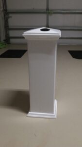
Figure 7. Deck-Post Sleeve. The antenna base and tilt-over mechanism is concealed in an 8” x 8” vinyl deck-post sleeve.
Tilt-Over Mount Hardware Modifications
The DX Engineering 6-BTV OMNI-Tilt Vertical Antenna Tilt Base, DXE-OMNITILT-1P [49], Figure 8, has received minor modifications so that it may be concealed within an 8″ x 8″ vinyl deck-post sleeve manufactured by Superior Plastics and sold by Penn Fencing [50]. The lengths of some of the stainless steel hex head bolts were shortened and some stainless steel jam nuts were used in place of stainless hex nuts, because they are not as thick. The actual OD of the ground-mounting pipe cannot exceed 1-1/2″, or the mechanism will not fit. Some bowing of the sleeve is evident, but this is always present. The mechanism has been fit-checked. A right angle adapter [51] provides access to the SO-239 connector.
Changes to DX Engineering hardware kits and ground mounting pipe are easy, and the changes have been listed below. Replacements were obtained from Fastenal [52] in 18-8 (304) stainless steel for all hardware kit changes. A stainless 1.5″ OD x 0.156″ wall thickness ground mounted pipe was obtained from OnlineMetals.com [53].
- Use 1.5″ OD x 0.156″ wall thickness ground mounted pipe (the actual 1.5″ OD dimension is critical)
- Change the DXE-OTMC-250C [54] kit from 5/16″-18 x 4-1/2″ long Hex Bolt, Full Thread, 18-8 Stainless Steel to 5/16″-18 x 2-3/4″ long Hex Bolt, Full Thread, 18-8 Stainless Steel.
- Change the DXE-OTMC-250C kit from 5/16″-18 Hex Nut, 18-8 Stainless Steel to 5/16″-18 Hex Jam Nut, 18-8 Stainless Steel.
- Change the DXE-OMNITILT-1 kit from 5/16″-18 x 1-1/2″ long Hex Bolt, Full Thread, 18-8 Stainless Steel to 5/16″-18 x 1-1/4″ long Hex Bolt, Full Thread, 18-8 Stainless Steel.
The changes to all listed items are critical and must all be completed, or the mechanism will not fit within the 8″ x 8″ deck-post sleeve. Once carefully tightened, the thin jam nuts will be fully threaded. No changes to the flat washers and lock washers provided by DX Engineering have been made.
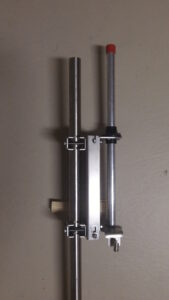
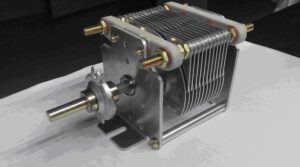
Figure 8. DXE-OMNITILT-1 Tilt-Over Base. The DXE-OMNITILT-1 tilt-over mechanism is shown clamped to the 1-1/2″ OD stainless steel pipe that has been embedded in a concrete foundation. One of the 6-BTV base insulators is visible, as is the RF right-angle connector.
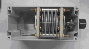
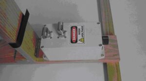
Figure 9 provides a top view of the deck-post sleeve with the DXE-OMNITILT-1 and 6-BTV base (red cap) installed. The entire assembly fits within the 8” x 8” sleeve once thin jam nuts have been installed.
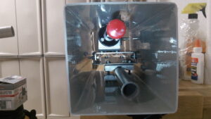
Figure 9. Top View of Deck-Post Sleeve. The 6-BTV base (capped) and DXE-OMNITILT-1 tilt-over mechanism clamped to the 1-1/2″ OD mounting pipe are visible.
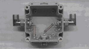
Figure 10 provides a better view from the bottom of the deck-post sleeve. The DXE-OMNITILT-1 is clearly visible as is the base insulator of the 6-BTV and right angle RF adapter.
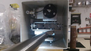
Figure 10. Bottom View of Deck-Post Sleeve. The RF connections to the 6-BTV base are visible, as are the tilt-over mount and stainless steel mounting pipe.
Static Charge Bleeder Resistor and Ground Straps
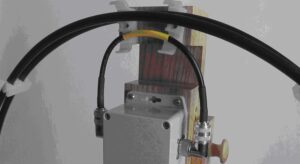
Figure 11 shows a 3 MEGOHM carbon film bleeder resistor [55] connected between the antenna feed-point and ground. This has been waterproofed within a piece of shrink tubing. The ends have been sealed with Loctite SI 5011 CL Ultraflex Non-Corrosive RTV [56]. This will bleed static charge from the antenna when the DC grounded step-down transformer or shunt matching coil is not present, as will be the case on 10 and 15m. The tinned ground braids in the photo are temporary, and copper ribbon will become the permanent fix to provide a low resistance path to the radial plate.
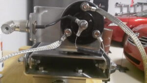
Figure 11. The 6-BTV Base. The RF connections, bleeder resistor (see text), and temporary ground straps are visible. The straps were replaced with solid copper ribbon.
Deck-Post Sleeve Modifications and Rain Collar
The deck-post sleeve cap has to be modified so that the flagpole 2-1/2″ OD fiberglass tubing (not the mounting pipe) can pass through it. Please refer to Figure 9 to see the 6-BTV tubing base with its red protective cover. The 2-1/2″ OD fiberglass tube will slide over this. The dimensions that were used to locate the hole in the deck-post sleeve cap are shown below in Figure 12. The hole has been bored out to 2-3/4″ to ensure 1/8″ clearance all around when the 2-1/2″ tubing is slipped into place. The positional dimensions should be verified for each and every installation, and a cardboard template should be constructed to ensure that the location of the hole is correct, as these caps are expensive. Please note that the hole is positioned in reference to the center of the deck-sleeve cap. Clamp the work, drill a small pilot hole, then use a new hole saw at low speed to bore through slowly.
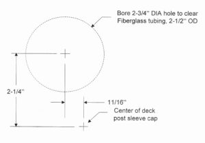
Figure 12. Boring Dimensions for Deck-Post Sleeve Cap. Please note the location of the center of the deck-post sleeve cap.
The finished deck cap is shown in Figure 13. If the cap has been bored correctly, the 6-BTV base tubing will be centered in the hole. If not, the fiberglass tubing will not be centered and will not clear the hole.
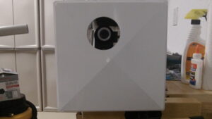
Figure 13. Top of Deck-Post Sleeve Cap. The 6-BTV and fiberglass tubing will clear the cap with room to spare.
In order to prevent water infiltration down the pole and through the cap, an Oatey All-Flash Rain Collar [57], Figure 14, 1-1/2 in. to 3 in., has been used. Rain collars are available at home improvement and plumbing stores. The reason that the hole in the cap was bored to 2-3/4″ and not 2-1/2″ was one convenience for assembly. There would be is plenty of lateral play in the deck-post sleeve and the flagpole if the hole were bored to 2-1/2″. In either case, a rain sleeve would be required.
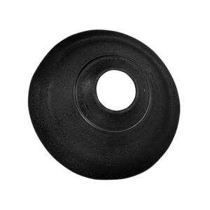
Figure 14. Oatey Rain Collar. It prevents rain from running down the fiberglass tube and into the antenna base.
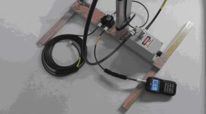
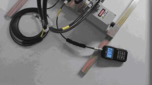
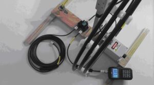
6-BTV Feed-Point Resistance and UNUN
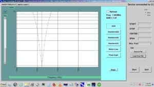
The 6-BTV was installed long enough to tune the traps. An MFJ-226 Vector Analyzer [58] was used at the feed-point of the 6-BTV. Ideally, the feed-point resistance for a quarter-wave radiator above a perfectly conducting ground plane should be half that of a center-fed dipole, or 36.5 ohms. Sadly, a feed-point resistance nowhere near 36.5 ohms would be observed on 3 of the 6 bands. The 10m trap could be adjusted so that the VSWR over the entire CW band was under 1.2:1. On 15m, the VSWR could be adjusted to under 1.3:1. Not so for the 20m trap. There, in spite of hours of tinkering with the trap sleeve and tubing below the trap, an acceptable match of under 2:1 could not be obtained. A great deal of time was spent inspecting the trap and searching for antenna and trap resonances. Convinced that the antenna resonant frequency had been found, the resistance was measured at the feed-point. The process was repeated for the 30m trap. There is no 40m trap. For the 20, 30, and 40m bands, the feed-point resistance was measured between 25 and 18 ohms. A shunt-matching coil like the DX Engineering DXE-VMN-1 [59] was considered in order to raise the feed-point resistance to a manageable one. Since K-type ferrite was available, a Jerry Sevick 2.25:1 UNUN was constructed for the feed-point. It provides a transformation to 22 ohms and is easier to construct than the one that transforms to 25 ohms. If you encounter similar matching problems, Balun Designs can supply a ready-made step-down transformer of this type, Model 1232 [60]. The mismatch is acceptable for the 20, 30, and 40m bands after the UNUN is installed. An alternative is to locate a remote antenna tuner at the base of the antenna. No difficulty was encountered when tuning the 80m resonator and stinger. The match over a 30 kHz segment at the bottom of the CW band was better than 2:1.
Line Choke
A line choke was added right after the UNUN to choke-off common mode currents that would otherwise travel to the operating position. The UNUN places the antenna at DC ground potential, so no other method is required to bleed static charge from the antenna. If the UNUN is not used, then the bleeder resistor shown in Figure 11 will bleed static from the antenna.
Matching to the 6-BTV Feed-point and Protecting the Remote Tuner
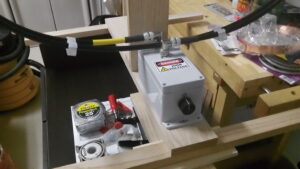
The 6-BTV is very well matched on 10 and 15m, but antenna impedance matching is required on the 20, 30 and 40m bands. An SGC-239 tuner [61] was tested at the base of the antenna, and it worked very well. Unfortunately, CW operation is restricted to 200W. This is inadequate for operation with the Ameritron ALS-600 linear amplifier [62]. Consequently, a 1 kW PEP Stockcorner JC-4 [63] was installed at the 6-BTV base. In order to conceal the tuner, a decorative circular pallet 24″ (61cm) in diameter was constructed from a white PVC trim board, Figure 15, and the tuner was fastened to the bottom of the pallet along with an input line choke, also visible.
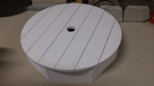
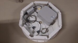
Figure 15. PVC Lumber Pallet. A synthetic, PVC lumber pallet (Top) conceals the Stockcorner JC-4 remote antenna tuner and a homebrew common mode choke (Bottom). Height is sufficient to prevent the tuner from sitting in a puddle of water.
The pallet height, 6-1/4″ (15.9 cm), is sufficient to keep the tuner above rainwater. The deck-post sleeve, Figure 16, now sits on top of the pallet instead of the radial plate.
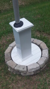
Figure 16. Flagpole Antenna Base Pallet. A deck-post sleeve and synthetic PVC lumber pallet conceal the tilt-over mount and remote antenna tuner. An Oatey rain collar prevents water from penetrating the deck-post sleeve cap.
Common Mode Noise Suppression
Seventy-five feet (23m) of LMR-400 [64] runs in buried conduit from the vertical to the shack. Control cable consisting of 75 feet of Carol C2543A, #18 AWG/4 with a shield [65] (try eBay for short lengths of this cable), has been pulled through the conduit, as the Stockcorner JC-4 [66] remote tuner requires a manual tune command as well as DC power. Line chokes, Figure 17, have been connected at each end of the LMR-400. These line chokes were tested after construction, and the procedure and test results have been provided in a separate article. As might be expected, the noise floor of the system is greatly improved. The photo below shows 11 turns of RG-400/U wound on a stacked 2 x FT240-43 core [67]. The 6th turn is a Joe Reisert crossover winding [68]. Whatever common mode choke is used, the real part of the impedance must be greater than the reactive part.
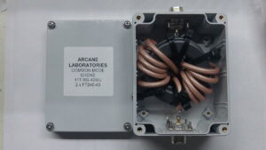
Figure 17. Homebrew Common Mode Choke. The choke consists of 11 turns of RG-400/U wound over 2 x FT240-43 ferrite cores.
Stockcorner JC-4 Remote Tuner Control Box Repackaging
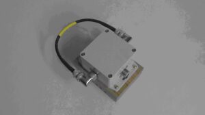
The control box that was provided with the Stockcorner JC-4 remote tuner has been repackaged, Figure 18, with a 4-pin microphone connecter [68] and 2.1mm power connector[69] for convenience. These connectors are readily available on Amazon or eBay. The housing is a Bud Industries PN-1320-DG [70]. In the future, the radio will control the remote tuner.
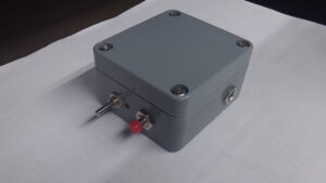
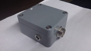
Figure 18. Remote Antenna Tuner Control Box. (Top) The tune command is asserted by depressing the red push button. The A or B antenna is selected with the toggle switch. (Bottom) The tuner is powered through the 2.1mm DC connector on the side of the box. Control signals are routed to the tuner through a 4-pin microphone connector.
References
[1] http://www.new-tronics.com/main/html/base_hf_6_band.html
https://www.dxengineering.com/parts/hsr-6btv
[2] https://www.westmarine.com/search?Ntt=topside+enamel
[3] https://www.dxengineering.com/parts/dxe-omnitilt-1p
[4] Penn Fencing Inc., 647 Pittsburgh Rd, Butler, PA 16002
https://www.pennfence.com/
[5] http://www.stockcorner.nl/
[6] https://www.dxengineering.com/parts/dxe-radp-3
[7] https://www.amazon.com/Flagpole-Diameter-Aluminum-Silver-Pulley/dp/B00RKMO5SE
[8] https://www.amazon.com/Anley-Authentic-Flagpole-Ornament-Replacement/dp/B07CKPLMCH/ref=pd_bxgy_1/147-5873063-6165639?pd_rd_w=RnRpJ&pf_rd_p=c64372fa-c41c-422e-990d-9e034f73989b&pf_rd_r=BNEXDZCDWJE2TSZG9D84&pd_rd_r=9b2247db-1804-438f-a449-8ee723b008
[9] DX Engineering Radial Plate, op. cit.
https://www.dxengineering.com/parts/dxe-radp-3
[10] New-Tronics Antenna Corporation, op. cit.
https://www.dxengineering.com/parts/hsr-6btv
[11] https://www.homedepot.com/p/SAKRETE-8-in-x-48-in-Concrete-Form-Tube-65470075/100321209
[12] https://www.homedepot.com/p/STZ-1-1-2-in-x-10-ft-Galvanized-Steel-Pipe-315-112X120/100536541
[13] https://www.homedepot.com/p/Southwire-500-ft-14-Green-Solid-CU-THHN-Wire-11583258/203401602
[14] Radial Plate, op. cit.
https://www.dxengineering.com/parts/dxe-radp-3
[15] https://www.amazon.com/HongWay-Landscape-Heavy-Duty-Galvanized-Irrigation/dp/B088TDCC19?th=1
[16] https://www.dxengineering.com/search?SortBy=BestKeywordMatch&SortOrder=Ascending&keyword=fiberglass%20tubing
[17] Ibid.
[18] https://www.homedepot.com/p/1-1-2-in-x-10-ft-Sch-40-PVC-Conduit-A52BE12H/202352538
[19] https://www.dxengineering.com/parts/dxe-400maxdx075
[20] https://www.hyendcompany.nl/line_isolators/product/detail/224/1.5_30_MHz_Line_Isolator_Low_Band___Coax_Dual_Core – prod
[21] https://www.lowes.com/pd/Basic-Tan-Retaining-Wall-Block-Common-4-in-x-12-in-Actual-4-in-x-12-in/3010120
[22] https://www.lowes.com/pd/Rubberific-Red-Recycled-Rubber-24-in-Tree-Ring/3199899?cm_mmc=shp-_-c-_-prd-_-lwn-_-ggl-_-LIA_LWN_179_Landscape-Products-_-3199899-_-local-_-0-_-0&ds_rl=1286981&gclid=EAIaIQobChMI5fSZkZnl9wIVCuazCh0KSgRyEAQYBCABEgJHqPD_BwE
[23] DX Engineering 2-1/2″ OD fiberglass tubing, op. cit.
https://www.dxengineering.com/search/part-type/fiberglass-tubing/product-line/dx-engineering-fiberglass-tubing
[24] DX Engineering, op. cit.
[25] DX Engineering, 2-3/4” OD fiberglass tubing, op. cit.
https://www.dxengineering.com/search/part-type/fiberglass-tubing/product-line/dx-engineering-fiberglass-tubing
[26] Flagpole Truck, op. cit.
https://www.amazon.com/Flagpole-Diameter-Aluminum-Silver-Pulley/dp/B00RKMO5SE
[27] Finial Ball, op. cit.
https://www.amazon.com/Anley-Authentic-Flagpole-Ornament-Replacement/dp/B07CKPLMCH/ref=pd_bxgy_1/147-5873063-6165639?pd_rd_w=RnRpJ&pf_rd_p=c64372fa-c41c-422e-990d-9e034f73989b&pf_rd_r=BNEXDZCDWJE2TSZG9D84&pd_rd_r=9b2247db-1804-438f-a449-8ee723b008
[28] https://www.dxengineering.com/search?SortBy=BestKeywordMatch&SortOrder=Ascending&keyword=DXE-RLT
[29] https://www.3m.com/3M/en_US/p/c/ppe/
[30] https://www.stanleytools.com/products/tool-storage/sawhorse-workbench/2-pk-2-way-adjustable-saw-horse/stst60626
[31] https://www.homedepot.com/p/RIDGID-Thru-Cool-6-Amp-1-Handed-Orbital-Reciprocating-Saw-Kit-R3031/100646504
[32] https://www.lowes.com/pd/LENOX-Diamond-8-in-Grit-Wood-Metal-Cutting-Reciprocating-Saw-Blade/1003019144?cm_mmc=shp-_-c-_-vf-_-tol-_-ggl-_-SS_Lenox-_-1003019144-_-local-_-0-_-0&&ds_a_cid=279391351&gclid=EAIaIQobChMIv7KBgJ7l9wIVAorICh0f-AoSEAQYASABEg
[33] https://www.homedepot.com/p/Oatey-1-1-2-in-x-2-yd-Solder-Plumbers-Cloth-Abrasive-Grit-Roll-314112/100346540
[34] https://www.henkel-adhesives.com/us/en/product/gasketing-sealants/loctite_si_5011cl.html
[35] DX Engineering, DXE-OMNITILT-1P, op. cit.
https://www.dxengineering.com/parts/dxe-omnitilt-1p
[36] Flagpole Truck, op. cit.
https://www.amazon.com/Flagpole-Diameter-Aluminum-Silver-Pulley/dp/B00RKMO5SE
[37] Finial Ball, op. cit.
https://www.amazon.com/Anley-Authentic-Flagpole-Ornament-Replacement/dp/B07CKPLMCH/ref=pd_bxgy_1/147-5873063-6165639?pd_rd_w=RnRpJ&pf_rd_p=c64372fa-c41c-422e-990d-9e034f73989b&pf_rd_r=BNEXDZCDWJE2TSZG9D84&pd_rd_r=9b2247db-1804-438f-a449-8ee723b008
[38] Miami Cordage Co., Inc., 2475 NW 38th St, Miami, FL 33142
[39] https://www.homedepot.com/p/Everbilt-6-in-Nylon-Dock-Cleat-41714/205883081
[40] https://www.homedepot.com/s/cleats?NCNI-5
[41] https://www.lowes.com/search?searchTerm=cleat
[42] https://www.grandnewflag.com/flag-sizing-chart/
[43] West Marine, Interlux, op. cit.
https://www.westmarine.com/interlux
[44] Deck Post Sleeve, Penn Fencing, op. cit.
https://pennfence.com/p/vinyl-post-sleeve-8x8x38-white
[45] DX Engineering DXE-OMNITILT-1P, op. cit.
https://www.dxengineering.com/parts/dxe-omnitilt-1p
[46] Deck Post Cap, Penn Fencing, op. cit.
https://pennfence.com/p/8-sq-new-england-post-cap-white
[47] https://pennfence.com/p/vinyl-post-skirt-8×8-one-piece-white
[48] https://www.oatey.com/products/flashings/rain-collars
[49] DX Engineering DXE-OMNITILT-1P, op. cit.
https://www.dxengineering.com/parts/dxe-omnitilt-1p
[50] Deck Post Sleeve, Penn Fencing, op. cit.
https://pennfence.com/p/vinyl-post-sleeve-8x8x38-white
[51] https://www.digikey.com/en/products/detail/amphenol-rf/83-1AP/80258
[52] Fastenal, Winona, MN,
https://www.fastenal.com/
[53] https://www.onlinemetals.com/?gclid=EAIaIQobChMIx-SZ967l9wIVRAJMCh3legyFEAAYASAAEgKfJvD_BwE
[54] https://www.dxengineering.com/search/part-type/saddle-clamps?fr=part-type&SortBy=BestKeywordMatch&SortOrder=Ascending&keyword=DXE-OTMC-250C
[55] https://www.mouser.com/ProductDetail/Ohmite/MOX-1-123004F?qs=r4Z5oksfPX0%252BxaVVECEGrA%3D%3D
[56] Loctite SI 5011 CL Ultraflex Non-Corrosive RTV, op. cit.
https://www.henkel-adhesives.com/us/en/product/gasketing-sealants/loctite_si_5011cl.html
[57] Oatey Rain Collar, op. cit.
https://www.oatey.com/products/flashings/rain-collars
[58] https://www.eham.net/reviews/view-product?id=12464
[59] https://www.dxengineering.com/parts/dxe-vmn-1
[60] https://www.balundesigns.com/1-2-unun-22-25-to-50-ohms-2kw-1232/
[61] https://www.sgcworld.com/239ProductPage.html
[62] https://mfjenterprises.com/products/als-600
[63] Stockcorner JC-4, op. cit.
https://www.stockcorner.nl/index.php/en/jc-4s
[64] DX Engineering, LMR-400, op. cit.
https://www.dxengineering.com/parts/dxe-400maxdx075
[65] https://www.digikey.com/en/products/detail/general-cable-carol-brand/C2543A-41-10/307352
[66] Stockcorner JC-4, op. cit.
https://www.stockcorner.nl/index.php/en/jc-4s
[67] https://www.mouser.com/datasheet/2/150/5943003801-1513292.pdf
[68] Reisert, Joe, W1JR, “Simple and Efficient Broadband Balun”, Ham Radio, Vol. 11, No. 9, September 1978: 12-15.
https://worldradiohistory.com/Archive-DX/Ham Radio/70s/Ham-Radio-197809.pdf