The idea was to use an IC-7300 to create a 100W station and use a Solar/Battery combination to power the setup. Solar/Battery made us “legal” as a SOTA activation. We combined two 90W solar panels which I had with an MPPT solar charging system and two LiPo batteries to create the power system for the activation.
All of this gear was carried to the site and setup in about an hour. A 25 ft. section of LMR-400UF coax completed the station. The mast was guyed with rings which allowed us to turn the mast/antenna combination to point the Yagi in any direction.
6M SOTA Activation
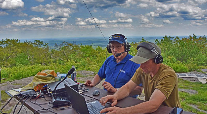
Anita, AB1QB, and Curtis, N1CMD Operating in the June VHF Contest
Between the SOTA/POTA activation and the June VHF contest, we made a little over 130 contacts on 6m. We did not have any real Es openings so most of our contacts were regional. Having the elevation provided by being on Pack Monadnock made us quite loud for the stations that could hear us. Several of our club members got on 6M and joined the fun. We did have a brief Es opening and managed to work a station in Alabama and one in Florida.
Mike, AB1YK Portable 6M
Mike, AB1YK has a much more portable 6M setup and used lower power to have some fun on 6M as well.
Al, KC1FOZ and Tom, KC1GGP Operating Portable
Al, KC1FOZ and Tom, KC1GGP put together a nice station and operated using battery power. Several other club members came out with a portable station or to watch and have fun as well.
Our first SOTA/POTA activation was a lot of fun and Anita and I are looking forward to the next one!
We decided to put up a third tower as part of our 2017 Field Day operation. The new tower will support a tri-band yagi and wire antenna for use by our Digital and GOTA stations this year. Our Field Day plans call for this tower to be located on the middle-level soccer field at the Hollis-Brookline High School. To overcome terrain limitations, we decided that our new tower should be a 60 ft setup.
The project began with some mechanical design and planning for a new, heavy-duty Falling Derrick System. Mike K1WVO, Dave N1RF and I secured the necessary materials and hardware to make the new Falling Derrick System.
Equipment And Tools On Site
The team in the two pictures above met at our QTH this past weekend to transport all of the equipment for the new tower to the high school for a test setup.
Setting Up The Tilt Base
The first step in the test was to locate the tower base in the center of our test area and ensure that it was level. Steel stakes were driven and retainers added to secure the base to the ground.
Building The Derrick
Next, we assembled the falling derrick and the first section of the tower to the base.
Assembling The Tower
With the Derrick in place, we assembled the remaining sections of our 60 ft tower on the ground.
Driving Guy Anchors
WIth the tower, Derrick and base together; we carefully located and drove the steel stakes for guying the tower, the derrick and for anchoring the pulleys associated with the falling derrick system. With this done, we made up and attached two levels of guys between the tower and the anchor stakes.
Completed Heavy Duty Derrick System Ready To Lift
The tower is lifted by two wire cables which run between the derrick and the tower. We made these cables up to length during our test session. Multiple cables are used to ensure that the tower is fully supported during the lift.
Completed Derrick System – A View of the Tower
Here’s another view of the tower and Derrick prior to the lift. We supported the tower on a ladder to make the initial lifting easier. The ladder will also be needed on Field Day to allow our tri-band yagi to be installed on the tower prior to standing it up.
Capstan Winch Used To Lift Tower
There is a considerable amount of rope that needs to be pulled through several pulleys to lift the Tower/Derrick system. The pulleys provide mechanical advantage and slow the lift rate to a safe level. We used a heavy-duty gasoline powered capstan winch to pull the considerable length of rope required to lift our tower into the full upright position
Lifting The Tower
With our crew fully briefed on the process and safety procedures, it was time to lift our tower. The picture above shows the lift in progress. Our setup ensures that no one needs to be in the tower’s fall zone during the lift.
The Tower Is Up!
Here’s a picture of the tower after it was up and fully guyed. Our new heavy-duty Derrick system worked very well and lifting the tower was completed smoothly and safely with very modest effort.
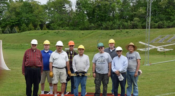
The Nashua Area Radio Club Tower Test Team
After a few pictures, we took the tower down and disassembled it. We had quite a few members turn out to help us with our new tower test. Thank you to everyone who pitched in to make our third tower project a success! We are looking forward to using it during Field Day 2017!
Notice: falling derrick tower systems can be dangerous if they are not engineered, built and used properly by a well-trained team. The tower system described here is unique and is not a standard falling derrick system. Significant steps and material choices were taken to ensure the safe use of the system described here to put up our tower Time was spent to train the team who used the Derrick system to use it correctly and safely. We do not recommend the system here to others as the engineering, materials, and training required for its safe construction and use may not be readily available.
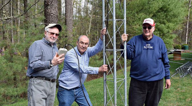
As Field Day 2017 approaches, Dave, N1RF; Mike, K1WVO, Don, KC1CRK and I got together to assemble and test two of the Yagi’s that we are planning to use for Field Day this year.
New 6m Yagi
I’ve contributed a new 6m Yagi for Field Day this year – an M2 Antenna Systems 6M5XHP. This antenna has 5 elements on an 18 ft boom. This antenna is fairly lightweight for its size and performs great – perfect for Field Day.
Tuning the 6M Yagi
We installed it on two tower sections (20 ft) of so that we could properly adjust its tuning.
Final 6M Yagi Test on Tower
We found that we could adjust the antenna’s driven element and hairpin match for the best SWR performance with the tower tilted over and the antenna on its side. We got nearly the same SWR performance this way as we saw with the tower and antenna tilted up 20 ft off the ground.
Final 6M Yagi SWR
After several adjustments with the tower up and down, we finally came up with an SWR curve that looked good.
Installing the WRTC Tribander on the Test Tower
The club purchased a WRTC tower and Triband Yagi a little while back and this Field Day will be the first time that we’ve had a chance to use this combination. We found that the phasing system and feed point for the WRTC Tribander had been misplaced so we made a replacement for these parts and we wanted to test the WRTC Tribander’s performance with the new parts.
WRTC Tribander on the Tower
After a quick check of the WRTC Tribander’s SWR performance with the tower tilted over, we stood the tower up and measured its SWR performance on 10m, 15m, and 20m.
WRTC Tribander SWR on 20m
The antenna’s SWR performance with its new phasing lines and feed point looked great on all three bands!
We ended the day by disassembling the two Yagi’s and taking down the tower. With this project done, we’ll be working on a falling derrick system for our third tower for Field Day.
A big Thank You! to Dave, Mike, and Don for helping with this project. It was a lot of fun!