Category Archives: Antennas

Articles about Antennas, Feedlines, Towers and related equipment. Fixed, Portable and Mobile Antenna Articles are included.

Homebrew ADS-B antenna for airplane tracking

Flight Tracking

December will bring Thomas Kavanaugh, KC1ELF, for a presentation on Plane Tracking with ADS-B. This is something you can do in your own shack for very little cost if you’re willing to do a little work. Mr. Kavanaugh will provide us with a great overview in December’s General Meeting, and I’ll follow that up with a Tech Night RTL-SDR Workshop where we’ll make, among other things, a software defined radio to receive ADS-B signals.

In this article I’m going to show you how to make an antenna for ADS-B using just a little coax with a BNC connector, a bottle cap, a little wire, and a hot glue gun.

Designing an antenna for 1090 MHz

ADS-B is transmitted on 1090 MHz. For most of us, that frequency range is outside our experience. Fear not. Everything you know about making a dipole still works for this. The frequency is 1080 MHz so the length of each side of the dipole should be 234/1080 = 0.217 feet, or 2.6 inches. Not very big!

An antenna that small needs to have something solid to hold it to the coax. Below is my solution. I cut two wires to a little more than 2-1/2 inches in length. Then I took a plastic bottle cap and drilled holes for coax through the top and the two wires on the side. Figure 1 below shows this partially assembled.

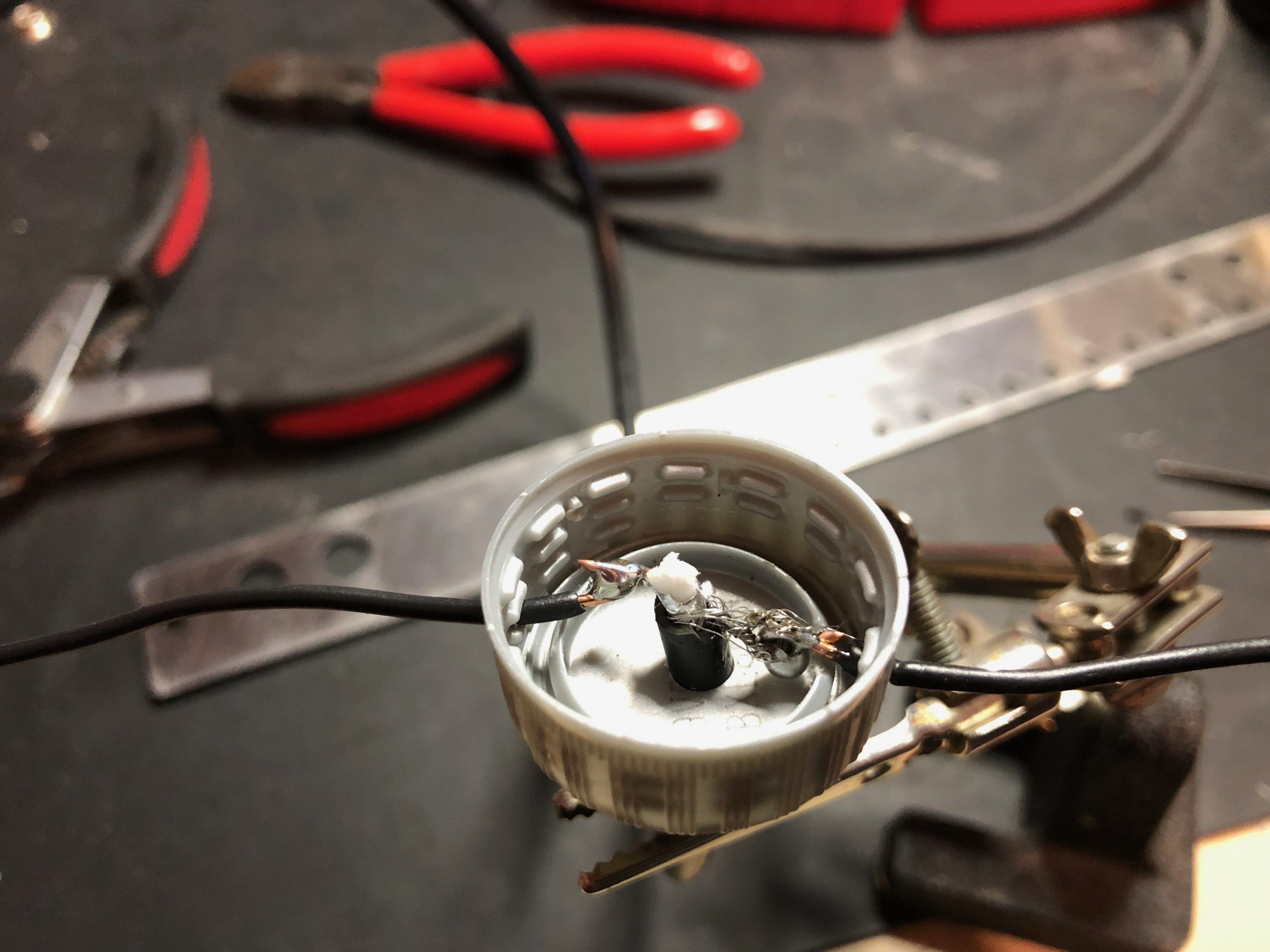
Figure 1. Coax to dipole wire connections.

I began with a short coax jumper fitted with two male BNC connectors. I just cut one of the connectors off and fed the bare end through the top of the bottle cap. Then I soldered the short wires to the center conductor and braid of the coax. It was a tight fit in there, and the braid of this coax really didn’t like to be soldered, but the final connection was good enough to proceed.

Finally, we want to fix all these connection into something solid. For that I used a hot glue gun to partially fill the bottle cap. This is shown in Figure 2 below.

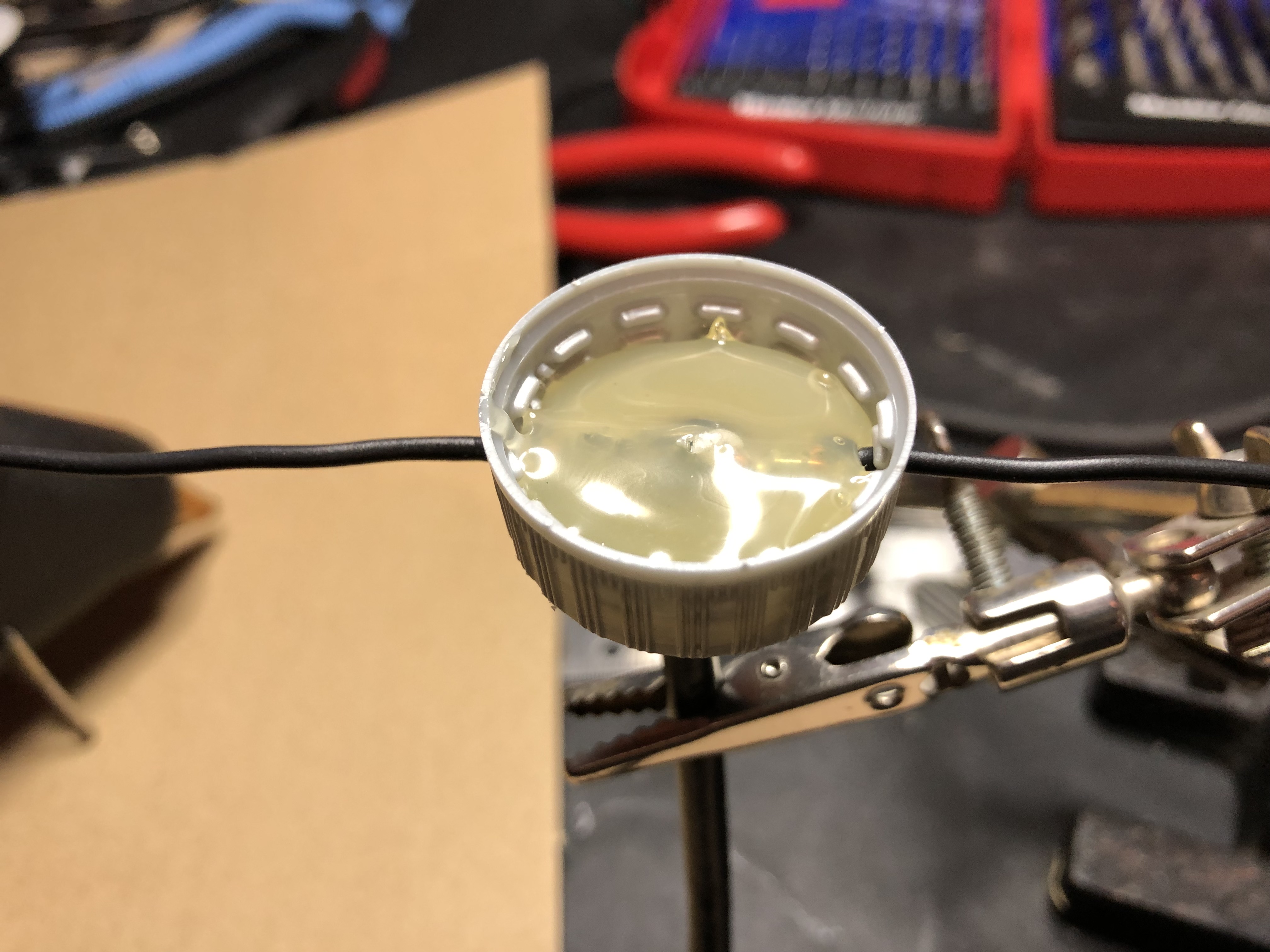
Figure 2. Connections potted with hot glue

Installing the antenna

ADS-B transmissions are vertically polarized so it is important to hang the dipole with the elements in a vertical orientation. Here’s an earlier prototype of mine hanging in my attic. Just a single brass hook (and a zip tie) was all it took to get the antenna installed. See Figure 3.

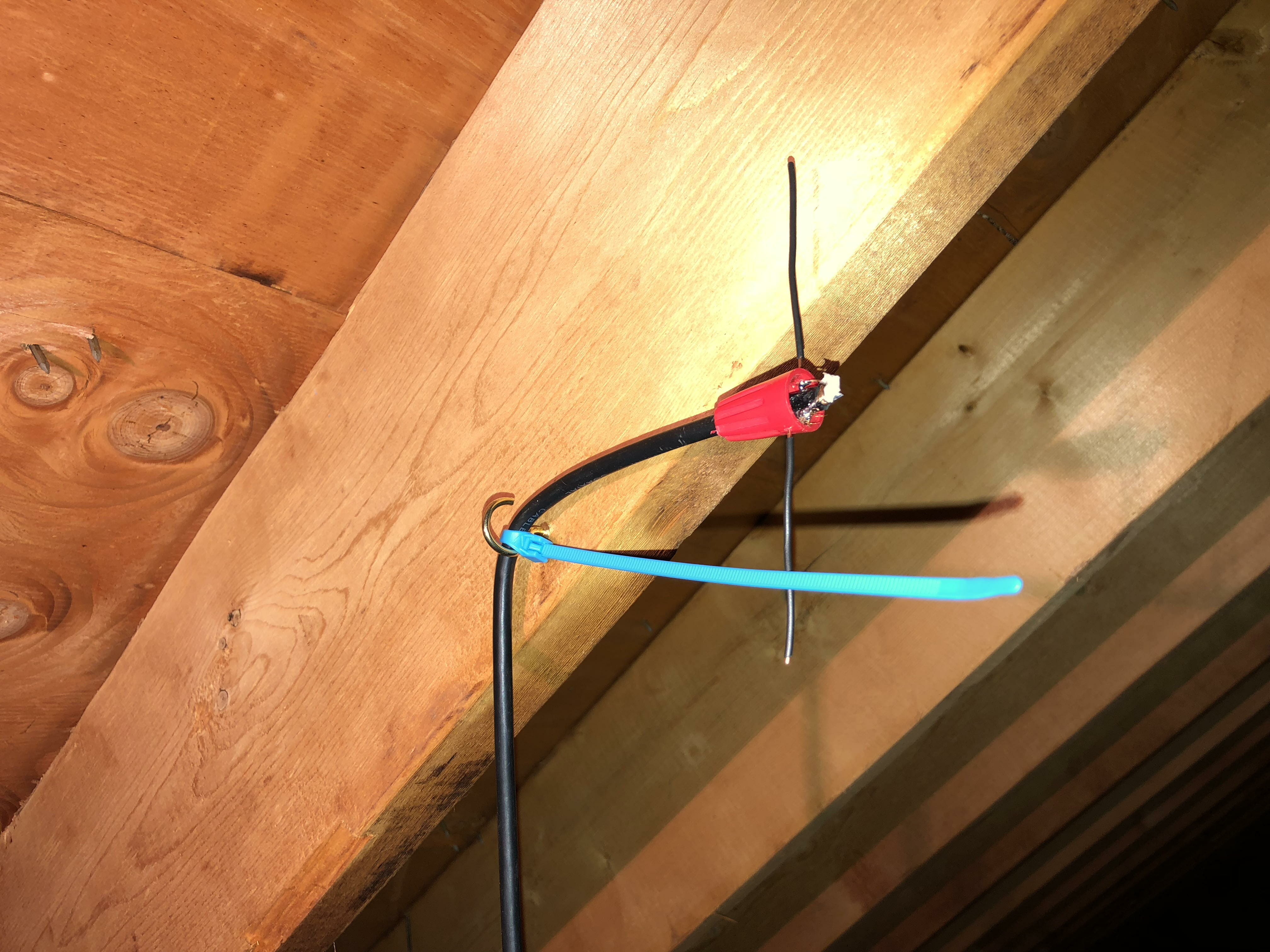
Figure 3. Installing the antenna for vertical polarization.

Looking Ahead

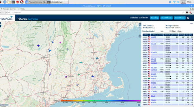
I’ll be doing an article on building a Raspberry Pi computer capable of doing flight tracking later this month. It will need an antenna like this to work, though, so here’s your chance to do your homework early!

Add SDR Capabilities to Your Radio [part 2]

In my last post, I discussed how to add an SDR to your station using the built-in capabilities of your radio. If your radio doesn’t have this fancy antenna switching and selection feature, you can still integrate an SDR pan adapter into your shack using the handy MFJ-1708B or MFJ-1708B-SDRS devices.

SDR Capabilities
Antenna sharing device from MFJ

These devices can be used to allow your SDR to share the same antenna as your transceiver while protecting it from transmitted signals. It does this in one of two ways (or a combination).

  1. Key down input. Transceivers have a line that is used to trigger external amplifiers called key down or key out line. Usually, this line goes to ground when the transmitter is transmitting. (You should read your radio’s manual to verify this.) If you connect this device to this radio output then it will disconnect the SDR while you transmit.
  2. The device also has an RF sensing circuit that will disconnect the SDR from the antenna if it detects the transceiver transmitting.

Because these units use relays you might want to have a slight delay before reconnecting the SDR to the antenna after a transmission. That delay time can be selected by turning the “DELAY” control near the left edge.

The unit is simple to configure: connect power (12v) and your radio key out signal to “CTRL”,  then connect your transceiver, SDR, and antenna connections to the proper ports. Finally, adjust the delay control until it works for your style of operating. That’s it!

Here’s Pascal, VA2PV, with a quick overview of an earlier version of these devices.

Click the video above to see Pascal describe these devices

Note that Pascal is reviewing one of the earlier models of this device. MFJ made some improvements to these units almost immediately after they began shipping. Be sure to get the one with a “B” after the numbers to ensure you get the new-and-improved model.

MFJ actually makes two versions of the new model: one with a regular SO-239 connector for the SDR, and one with an SMA connector for the SDR. The SMA version is shown below.

SDR Capabilities
SMA version of the unit

Amazon has some nice patch cables for very little money to complete the project.

SDR Capbilities
SMA patch cables

Note: If you do have an external amplifier be sure to put the MFJ unit between your transceiver and the amplifier!

I’ll post a few more notes on SDRs and uses for them in your shack over the next month or so. Please plan to join us for the December 11th Tech Night SDR workshop where we’ll help you get your computer and SDR talking.

When the Wind Blows

As most of my friends in NARS know, I have been using a Hustler 6BTV multi-band vertical for the past 2 and a half years. It is concealed inside a long piece of PVC pipe configured as a flagpole. An ugly flagpole but it still passes the deed restrictions and keeps the vigilantes off my back. I have a piece of rope about a third of the way up the pole that is intended to counter gusty winds that predominantly come from the North. This arrangement has served me well, allowing me to log over 200 countries.

A couple of months ago, I was out in the garage one afternoon watching an approaching storm. As is often the case, the rains came down in buckets. In less than a minute, the winds came screaming out of the West at near-hurricane force, driving the rain sideways. The winds subsided to almost dead calm almost as quickly as they ramped up. I stood there stunned at what apparently was a microburst. I peered apprehensively toward my flagpole and discovered it laying on my neighbor’s tree. Oh oh, this can’t be good, I thought. I looked around the neighborhood and noticed that a palm tree two doors down had been snapped in half. Good thing I did not have one on my property.

I went over to the leaning pole to try straightening it. The resistance I experienced told that the antenna inside was bent. I relaxed a little knowing that perhaps I could straighten it out. I tied a rope about halfway up the pole and proceeded to pull it back to vertical. I applied considerable force to pull the pole up. As I neared vertical, the pole suddenly swung around toward me and was now leaning close to the house. Yep, this definitely was not good. If it wasn’t broken before, I feared it was broken now.

The next day my son and I lowered the stricken antenna to ground. As I pulled off the pipe, I noticed the mounting base support pipe was bent. The pipe is about a foot or so in length and inserts in the first section of the antenna. The wall thickness of the pipe is an eighth of an inch. The pipe had been bent to about 30 degrees from vertical by the wind load on the PVC. Figure 1 shows the damaged support as well as the first section that was also slightly bent.

Antenna
Figure 1 – Bent Antenna Support & First Section

The rest of the antenna was intact with no signs of damage. Normally, I would have used a large vice to Armstrong the bent pieces back to vertical. However, being workshop-challenged in The Villages, that was not to be. I have always believed a garage is for vehicles.

The next step was to contact DX Engineering to order a new base support and first section. While I was waiting for the new hardware to arrive, I thought of how I could strengthen the base to mitigate wind damage in the future. I recalled an article from an amateur in Colorado who strengthened his beams by inserting sections of tubing as the element junction points for increased rigidity. I borrowed this approach on my 40-meter beam to withstand the wind and ice of New England. After 20+ years the beam is still up and still straight. (At least it was when I sold the place.)

I made a trip to the local big box store and found a 3-foot piece of tubing that fits snugly inside the base support pipe and protruded about halfway out. The idea here is that, once the first section is clamped in place, the added piece acts as a stiffener that will prevent the first section from bending. I used this same principle when I installed my mast on my tower by inserting another pipe inside the mast. It too has never failed. Many thanks to John, WS1E for the idea. Figure 2 shows the modified configuration.

Antenna
Figure 2 – Modified New Base Section

I reassembled the antenna and slid it back into the PVC pipe. My son and I hoisted the pole back in place on my base mount. For future protection, I added another piece of rope to tie down to the West. (Don’t tell the XYL!) A check of SWR across the bands showed that I was back in business.

Now that things are back to normal, I leave you with these words of wisdom for your next antenna project:

When the wind blows,

Gently, my antenna will rock,

When the wind howls,

Down it will come with a hard knock.

Ed, K2TE

Radio Amateurs Developing Skills Worldwide