Category Archives: Antennas

Articles about Antennas, Feedlines, Towers and related equipment. Fixed, Portable and Mobile Antenna Articles are included.

6m Field Day Station

We’ve been busy getting ready for Summer Field Day 2021 at the Nashua Area Radio Society. Our plans include putting up a Tower, a Computer-Controlled Satellite Station, and an upgraded 6m Field Day Station.

6m Field Day Station - LFA Yagi
6m LFA Yagi

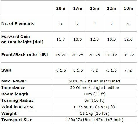
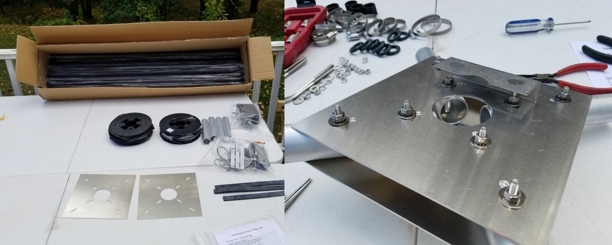
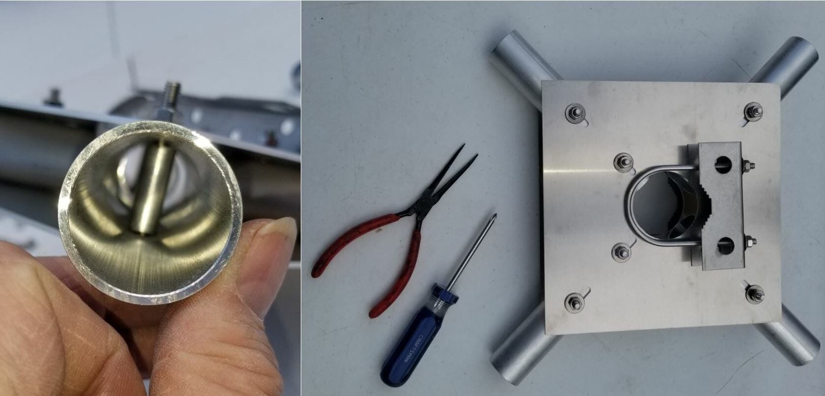
Our 6m Field Day station will be a portable setup and features a new antenna – a 3-Element Loop Fed Array (LFA) Yagi from InnoVAntennas. There are some advantages to LFA Yagi’s for the 6m band and above. In particular, Yagis using an LFA design are less susceptible to noise and interference which is a big advantage for weak-signal work on the 6m Band.

6m Field Day Station - LFA Yagi on Mast
6m LFA Yagi on Mast

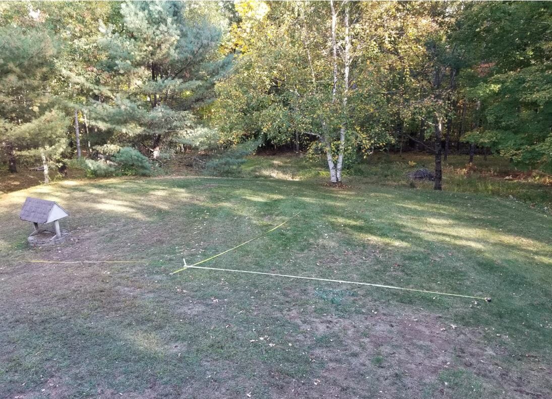
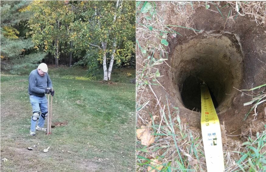
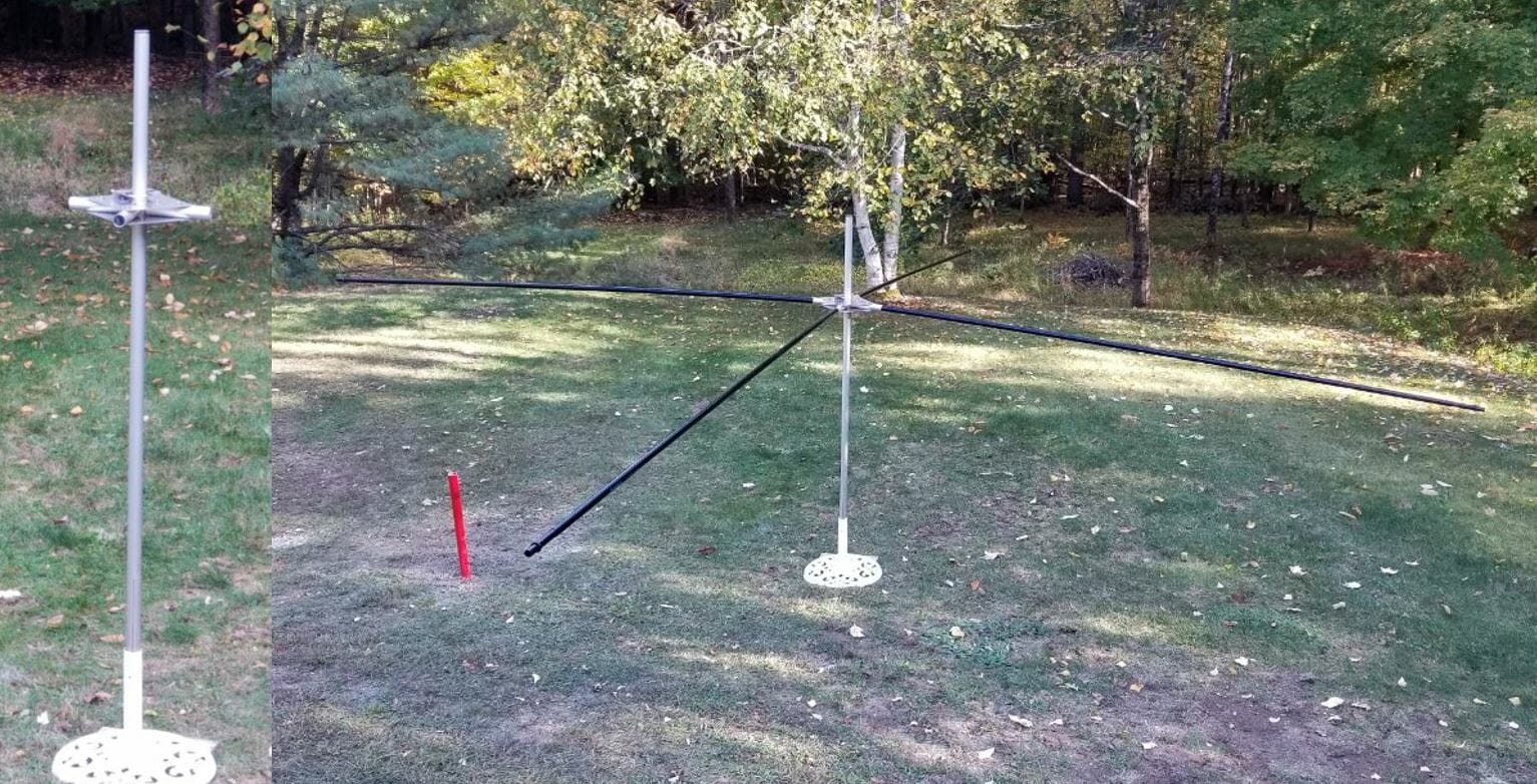
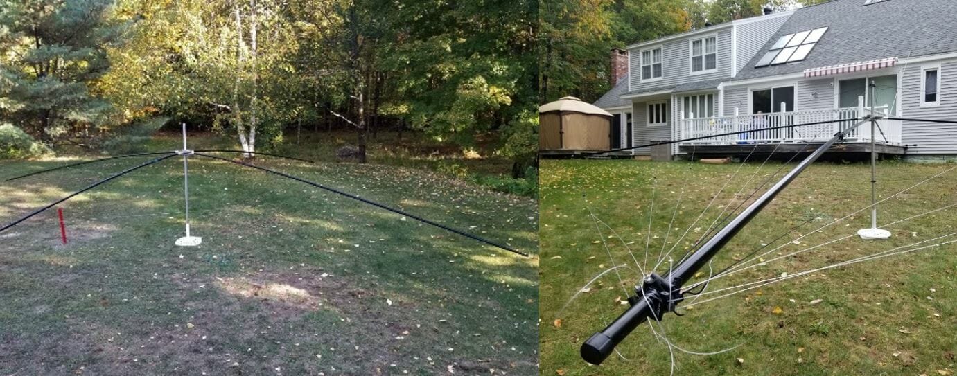
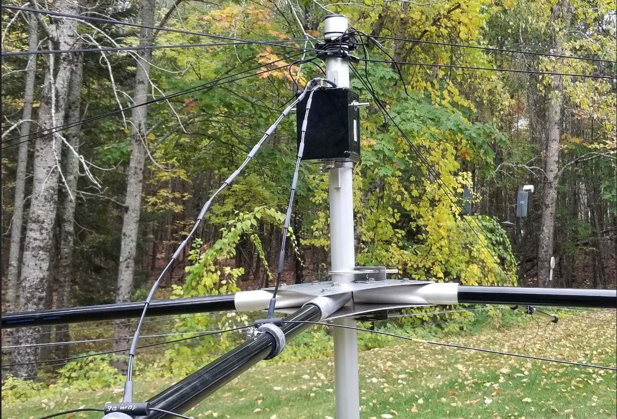
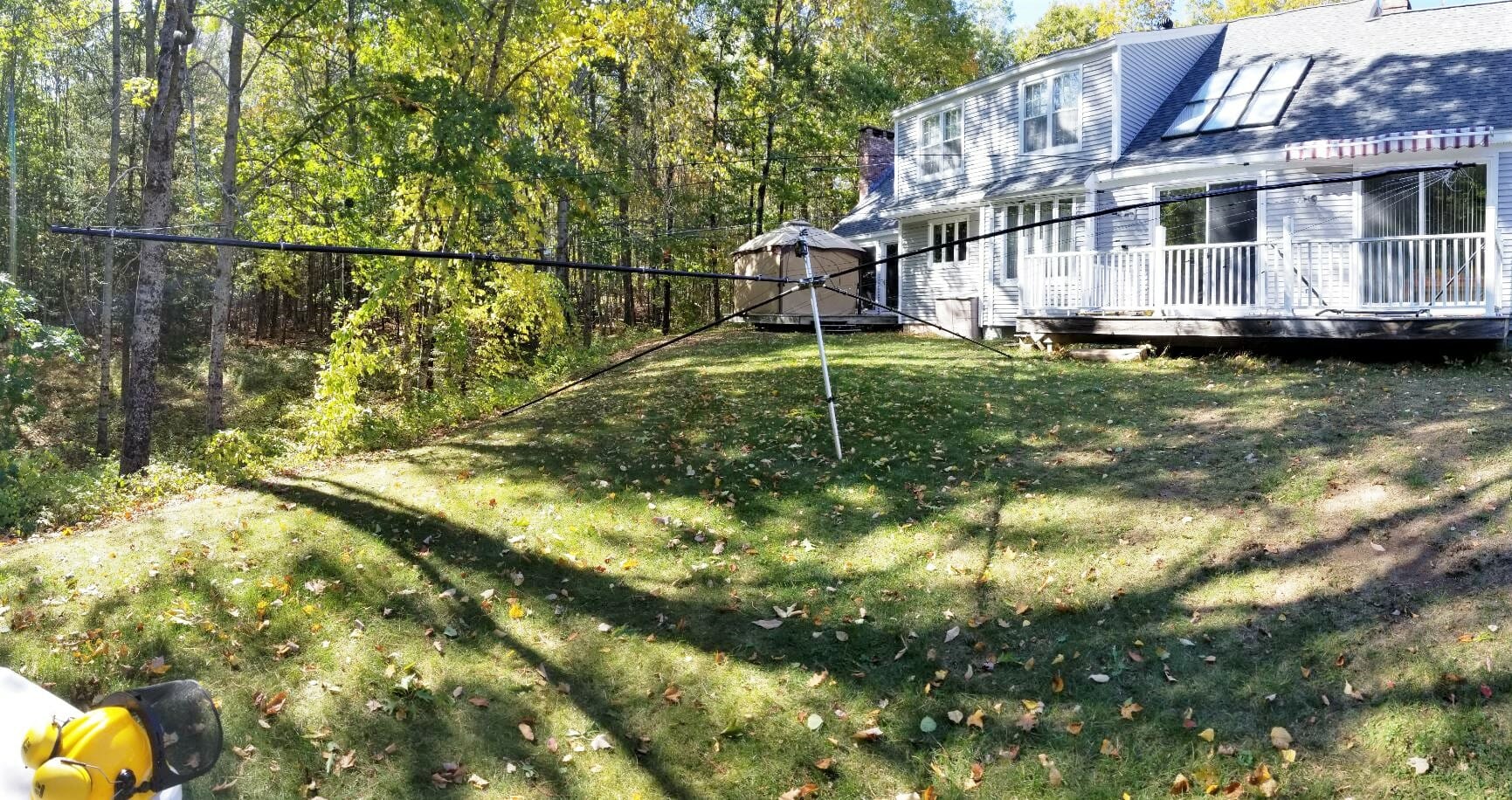
Our Yagi is lightweight which makes it ideal for portable applications like Field Day and Mount Topping. Aron, W1AKI, and Jamey, AC1DC helped me to assemble the antenna and put it up on a 25 ft fiberglass mast here at our QTH for testing. The antenna is fed with LMR-400uF coax and rigged with a rotator loop near the top of the mast so that the antenna can be pointed by rotating the mast at the base. The setup is easy to put up – it takes about an hour to do it.

6m Portable Station
6m Field Day Station

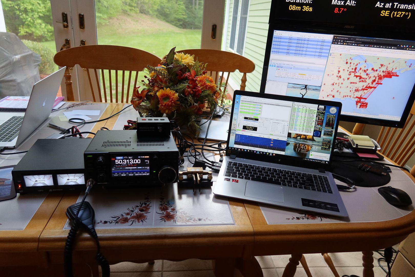
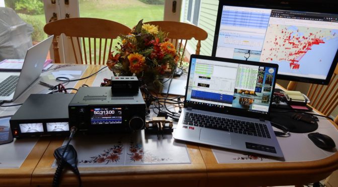
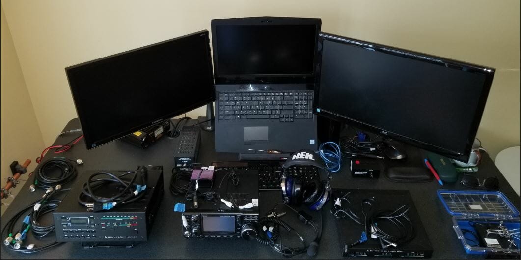
We also use the 6m LFA antenna project as an opportunity to assemble and test our 6m Station for Field Day. The station is an all-mode setup that can do SSB Phone, CW, and WSJT-X Digital (FT8/FT4, Q65, MSK144, etc.). The station will be generator powered at Field Day but it can also be run using a solar/battery setup when Mountain Topping.

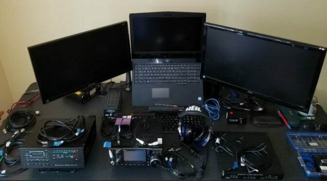
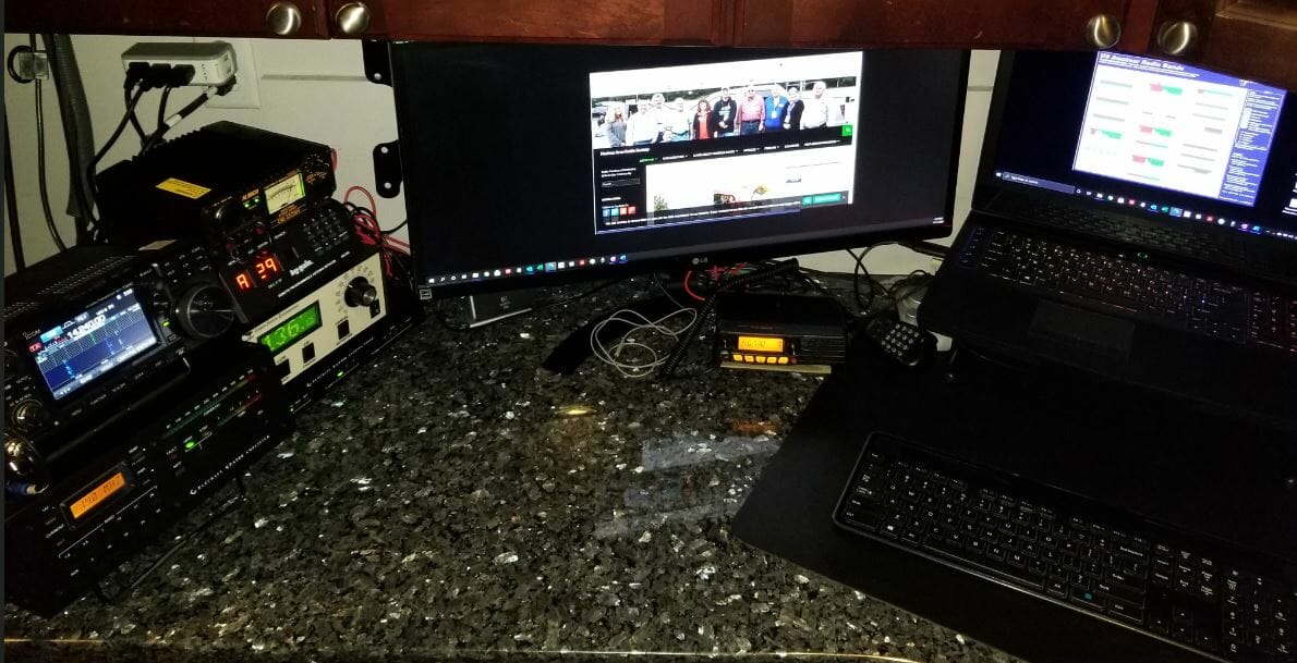
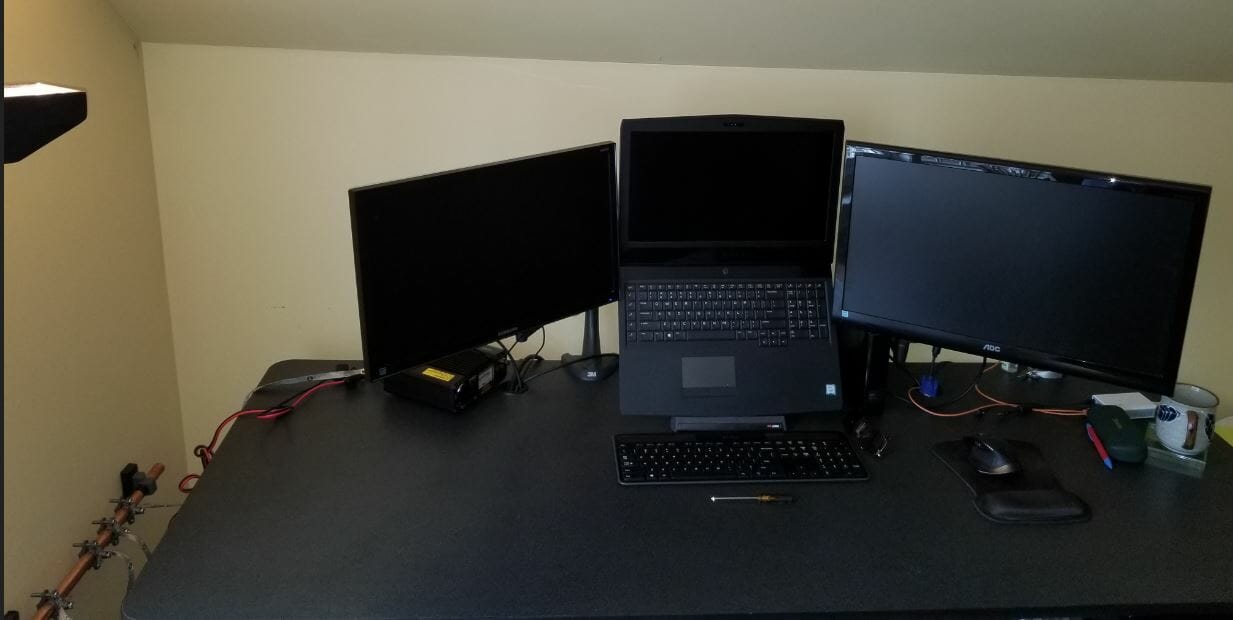
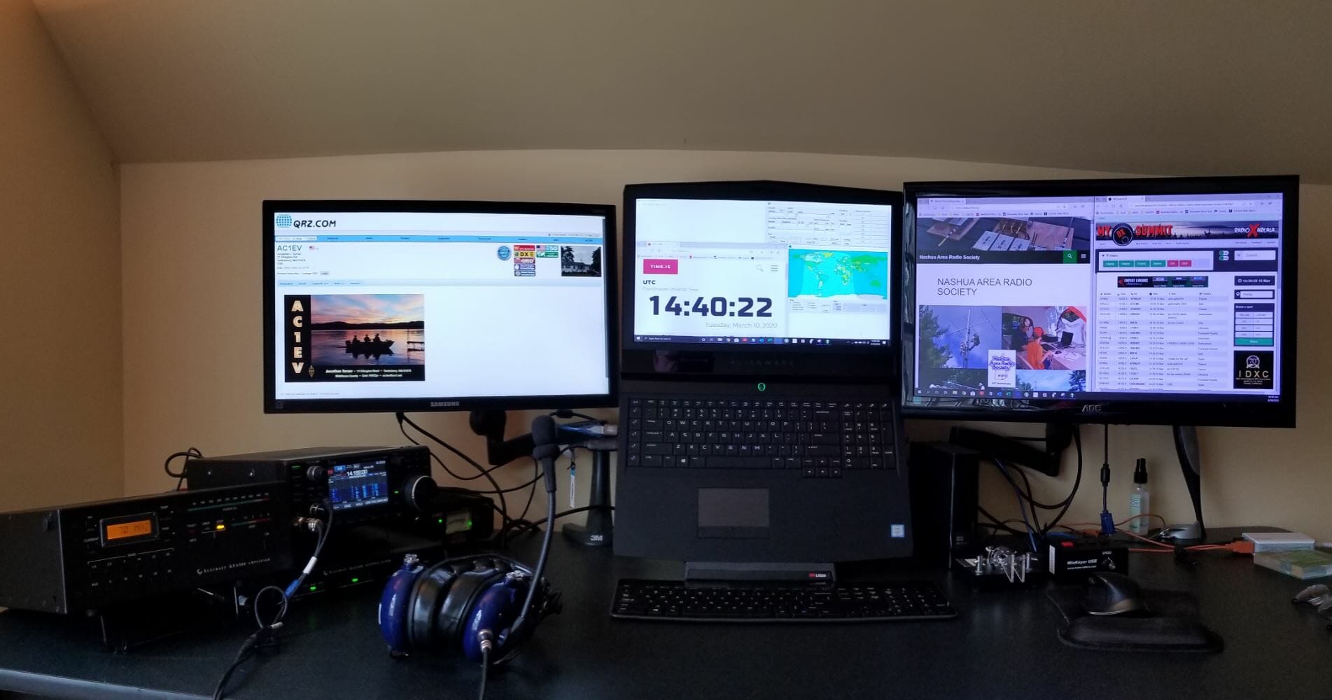
The station features an IC-7300 Transceiver (100w), a Winkeyer and Paddles for CW, and a Windows laptop computer running the N1MM+ logger and WSJT-X. The station will also sport a second monitor for Field Day.

N1MM+ Logger on 6m
N1MM+ Logger on 6m

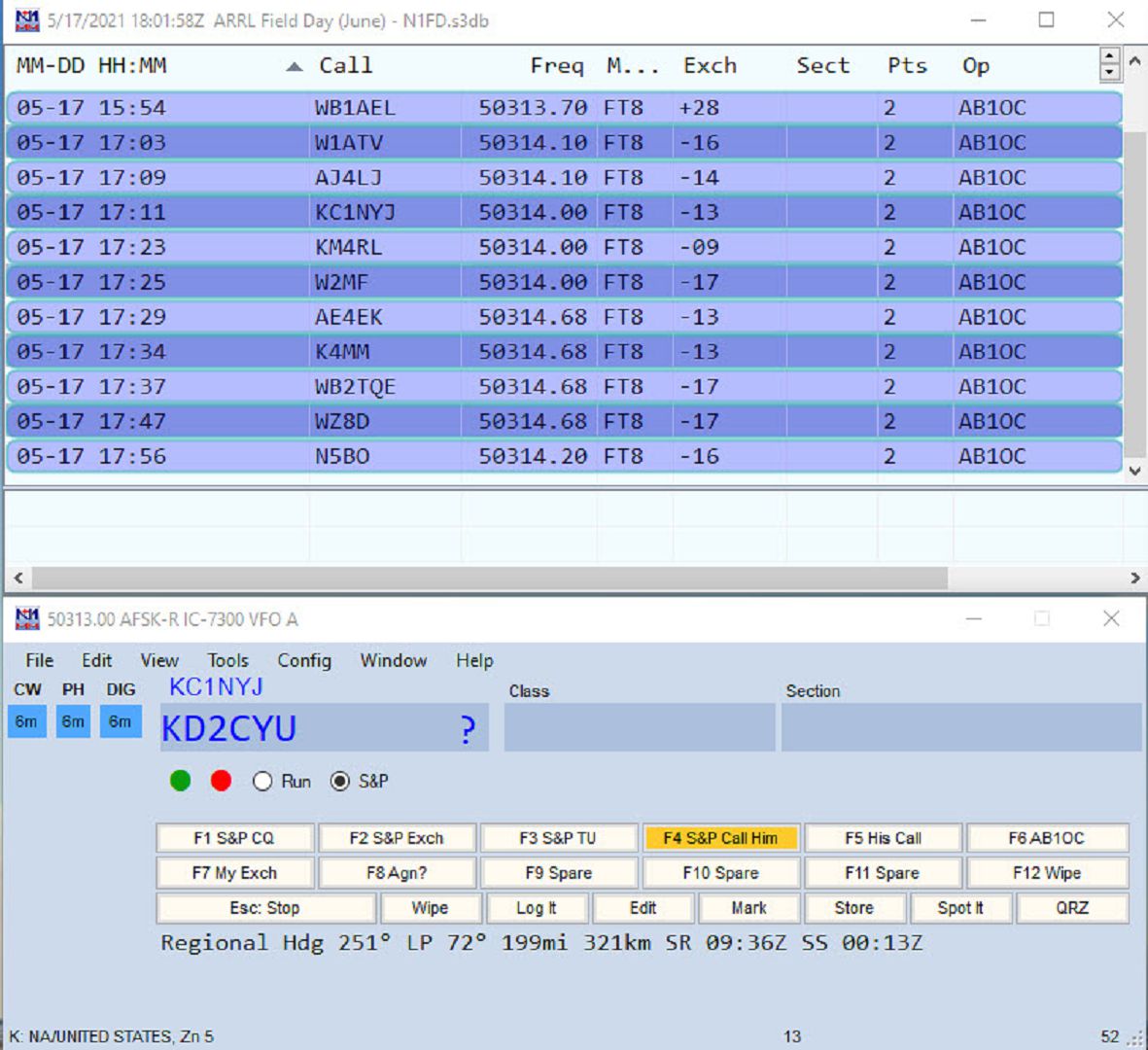
The N1MM+ Logger works great with the IC-7300 and WSJT-X digital. It supports the all-mode station configuration nicely and it is well integrated with WSJT-X making the logging of FT-8 and other Digital Mode contacts simple. N1MM+ also supports voice recording and keying of the IC-7300 which is a great aid during longer operating events like Field Day.

6m Field Day Station - PSKReporter Test of Portable 6m Station
PSKReporter Test of Portable 6m Station

So how does the upgraded setup play on 6m? Very well! The image above is a snapshot from PSKReporter during our testing session. As you can see, we were using FT8 to test the station and we were heard up and down the eastern U.S. states.

WSJT-X FT8 Decode using 6m Portable Station

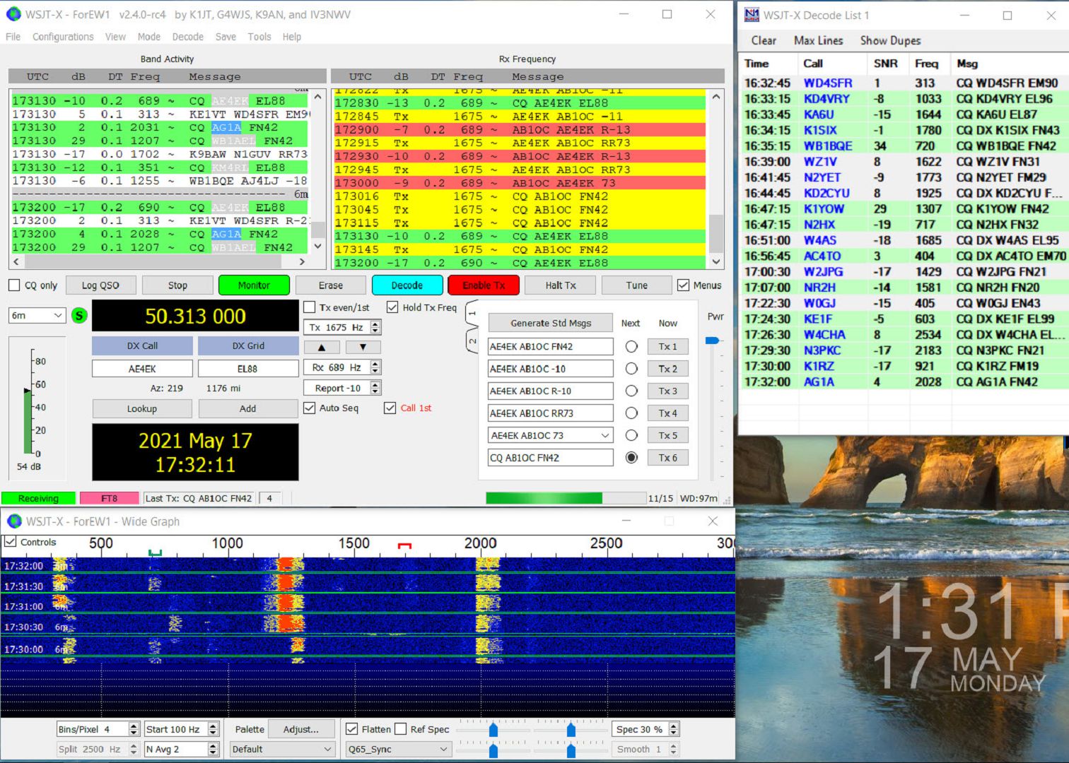
Signals were strong in WSJT-X FT8 mode and it was easy to make contacts. We made about 50 contacts during our testing of the 6m Feild Day Station.

The LFA Yagi hears really well making for reliable decodes of signals in the -18 range and often weaker.

6m Meteor Scatter Pings

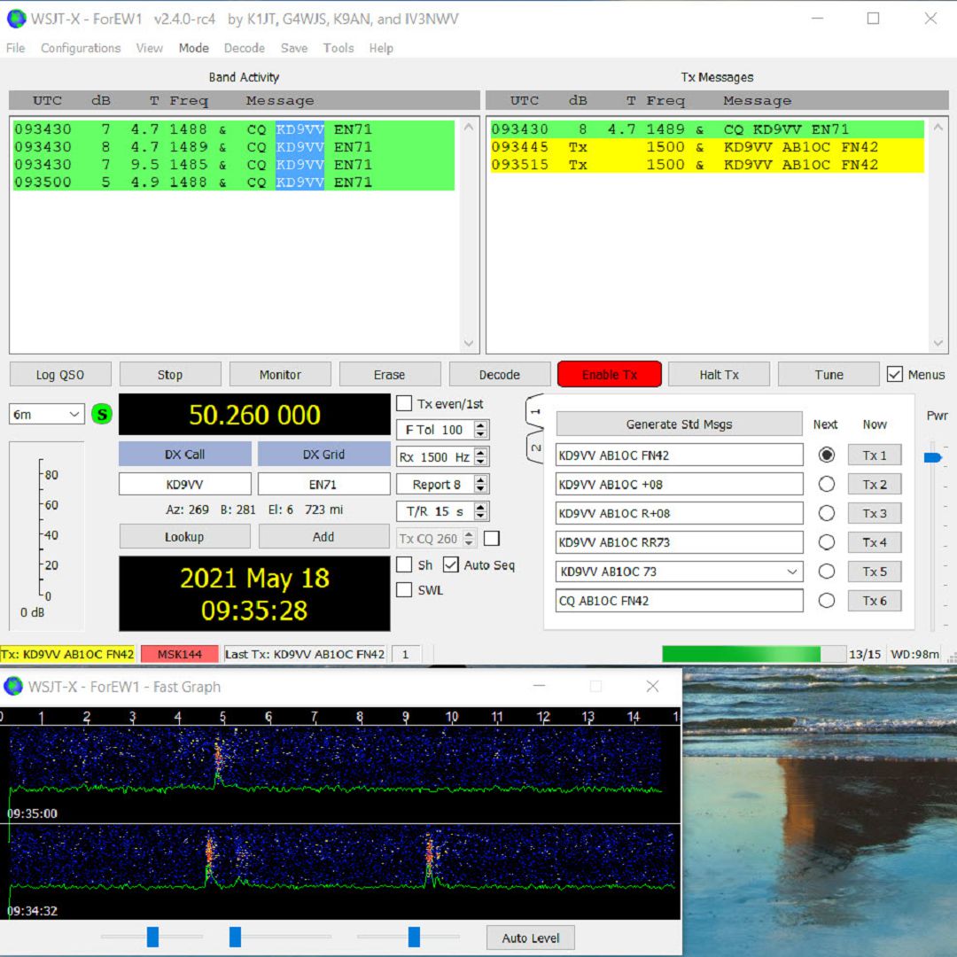
For fun, I decided to try some 6m Meteor Scatter contacts using the MSK144 mode. This is a challenge with a 100W station as Meteor Scatter general needs a bit of power to work well. As you can see from the image above, we had no problems decoding meteor pings from stations in the midwestern US. I even managed to complete a couple of contacts using Meteor Scatter on the 6m Band.

All in all, we are very pleased with the performance of our upgraded 6m Field Day Station. If we can get a similar Es opening to what we have been seeing here during the last two days, we should have a lot of fun on the Magic Band at Field Day!

Fred, AB1OC

AC1EV Spiderbeam Part 1 – Building the Antenna

Part 1, Building the Antenna and Base

Spiderbeam 5 Band HD Antenna

HD Spiderbeam Specifications

As shown in the specifications above the Spiderbeam has a 33-foot boom, so I measured carefully to find the best spot to build it and raise it on the mast.

Measure the site to locate the best place to install the mast.
Survey

Preparing the base for the mast

The Yaesu 800DXA Rotator that will rotate the mast and antenna will be mounted to a steel pipe buried and cemented into the ground.  The next step is to dig the hole.  The maximum reach of this post hole digger is around three feet.

Preparing the hole
Preparing the hole

Next, place the pipe in the hole and make sure it is vertical.

Set the Pipe
Set the Pipe

Add about 6 inches of gravel to the bottom of the hole to promote drainage, then add dry quick setting concrete to a few inches below the top of the hole.   Slowly add water to the dry mix and give it time to soak in.  One bag was sufficient.

Add Cement and Water

After adding water to the cement, I saw it was not draining very quickly.  I had the inspiration to use my palm sander, without any sandpaper, to vibrate the pole.  It worked great and you can see how the water level dropped and the bubbles coming out of it.  I am confident this made the concrete stronger.

Set the Cement
Set the Cement

Read the Manual Before  Antenna Assembly

While I wait for the concrete to cure properly, I will construct the antenna.  The Spiderbeam antenna packs into a compact box. The mast is a Spiderbeam 14.5 Meter HD model and is rated for full height with this antenna.  The 14.5 Meter HD telescoping mast has 9 sections.  Each section is around 6 feet long.  When fully extended it is 47 feet long.  Assemble the antenna directly onto the topmost section of the mast.

Antenna Box and Mast

Spiderbeam includes a printed booklet with detailed assembly instructions and you can also download a PDF with the latest version of instructions from their web site.  They will also provide plans to construct it yourself if desired.  After assembling their kit I can say that building this from scratch is a challenging project.  The components they provide are of high quality and worth the money.  I highly advise everyone to read the assembly instructions over at least twice before beginning work.  The manual includes instructions for the user who builds from scratch and also from the kit.  It covers the portable as well as the HD versions of the antenna.  Even after reading the instructions twice myself I still had to backtrack a few times to complete the assembly properly.

Beginning  Antenna Assembly

Open Box and hub
Open Box and hub

The box contains 20 fiberglass tube segments along with all the other parts required to assemble the antenna.  I purchased the optional Kit Assembly Service from Spiderbeam where they manufacture the wire elements, guy lines, balun, etc. This is very worthwhile and quite a time saver.  The two spools of wire shown above include all the reflectors, directors, and driven elements accurately measured.  The wires on the spools are in the correct order of use.  This makes it simple to access the next wire needed when assembling the antenna.  The wires are accurately measured, but they are not precisely tuned.  Do this once the antenna is fully assembled and off the ground a bit.

Hub and Sleeve Detail

The pictures above show some detail of the Spiderbeam Center Joint.  Where the bolts go through the tubes there is a sleeve to install in the tube to prevent it from collapsing when you tighten the bolts.  It takes some finesse to align the parts.  I used a very long nose needle nose pliers to hold the sleeve in the tube during assembly.  It is even more tricky when attaching the brackets on the top and bottom of the hub as many pieces need to be stacked up and aligned before you can insert the bolt through the sleeve.

Installing the Spreaders

Hub and Spreaders
Hub and Spreaders

To aid in the assembly I placed the topmost section of the mast into a garden umbrella holder.  Spiderbeam specifies that you install the hub 50cm from the top of the mast.  I found this to be a bit short and will make an adjustment in the future to make it 65cm.  This will give the top support guys more leverage for the spreaders. There are intermediate detailed steps as each component is installed.  The instructions keep it on track.

Installing the Wires

Spiderbeam Reflectors and Directors
Reflectors and Directors

The next step is to add the Reflectors and Directors.  I found it useful to have the antenna up high enough that I could easily duck under the wires as I put them on and adjust them.

Spiderbeam Balun
Balun

Before installing the driven elements install the balun on the mast.  There is a terminal label for each driven element.  Left and right sides are identified on each element and it is important to orient them correctly when connecting them to the balun. After this, install the wires in the order shown in the manual.

Completed Spiderbeam

Finally, I picked up the completed antenna and moved it out of the way so I would have room to work on the next phase, raising the Spiderbeam.  It weighs about 30 LBS. including the mast.  It is certainly the largest single item I ever lifted and moved.  There is lots of inertia to manage, but with care, I moved it easily.  You can see how large the antenna footprint is with it on the ground.  This is the end of Part 1.  Part 2 will be coming soon.

Jon, AC1EV

One Radio, Two Shacks

One Radio, Two Shacks

My wife and I have two houses, one in MA and the other in NH.  I can afford to have an antenna set up at each location but duplicating the radio and amplifier is more expensive.  The point of the article is to describe how I transport the interior of my shack from one QTH to another.  As a new ham, I focused on building a shack in my primary QTH in MA.  Additionally, I wanted to be able to operate from our second home in NH. My solution was to put some effort into putting up a good antenna there and I would just bring my “rig” up to NH when we went there.  I could have set up remote access from the NH QTH to my MA QTH, but there was something about the property that made me want to have an antenna up there.

Advantages of operating from two locations

The MA QTH is in Tewksbury, MA, and has all the RF noise present in a suburban environment.  Additionally, the terrain was flat, so my antenna height above my roof was all I had.  The NH QTH offered many advantages. The first was there were many tall trees over 80 feet high.  Another advantage was the house was on top of an 85-foot hill.   The RF environment in the rural forest setting was noticeably quieter.  Installing an antenna high up in one of the trees on top of the hill is powerful. I ended up installing an 8010 EFHW antenna from MyAntennas.com which you can view here.  This second article discusses the topography of the NH QTH and how well the antenna worked in the 2019 CQ World-Wide DX SSB Contest. A disadvantage to operating remotely was that power and internet at the NH QTH were not reliable and I could anticipate losing connectivity multiple times a year.  I think this is a good case for wanting to operate locally from both locations.  A few hundred dollars for the antenna installation was an amount I could handle that would not eat into the Ham budget for the primary station in MA.  Duplicating the major components of that station would cost around $4500 which may happen someday, but until then, I will transport them between shacks.

One Radio, Two Shacks – Moving the Components Between Shacks

Here is what my MA shack looks like

MA Shack - One Radio, Two Shacks
MA Shack

Icom 7300, Elecraft KPA500 amp, and KAT500 Tuner are the core components that need to travel between shacks.

When I arrive at the NH QTH this is what the shack there looks like.

Empty Desk
Empty Desk

In addition to the radio gear, I bring my laptop.

Laptop with 2 Additional Monitors

I packed all the gear required to set up the NH Shack in these two toolboxes.  Pelican cases would be great, but these were around $60.00 at Home Depot.  They are watertight and the bottom one has wheels.

Stacked Tool Boxes
Stacked Tool Boxes

Let’s unpack the smaller one on the top first.

Small Tool Box Full
Small Tool Box Full

Inside is the IC-7300, Heil Pro 7, and Bencher CW Key.

The big toolbox is full and quite heavy.

Big Tool Box Full
Big Tool Box Full

The box from the Pro7 headset holds the loose cables and fits in the toolbox perfectly.

Big Toolbox Middle Layer - One Radio, Two Shacks
Big Toolbox Middle Layer

The KAT500 Tuner is unwrapped.  You can see below how well the toolboxes fit the components.

Big Tool Box Bottom
Big Tool Box Bottom

Dummy Load and KPA500 amp on the bottom of the large toolbox.

Components Laid Out - One Radio, Two Shacks
Components Laid Out

Here are all the components laid out.  Key cords and cables are labeled.

Wires and Ground

I connected the components.  The copper pipe is a bus for common ground.  The wire on the right side connects to the house ground outside.  The radio is noticeably quiet.

NH Shack Ready
NH Shack Ready

The shack is ready.

One Radio, Two Shacks – Here’s How Set Up Goes…

Click on the above image for a hyper-lapse video of me putting the shack together.

Jon, AC1EV

Radio Amateurs Developing Skills Worldwide