February 14, 2017, now represents two important days: Valentine’s and Nashua ARC’s Feb Tech Night! Nothing else says love like telling that special someone — you want to solder some electronics 🙂
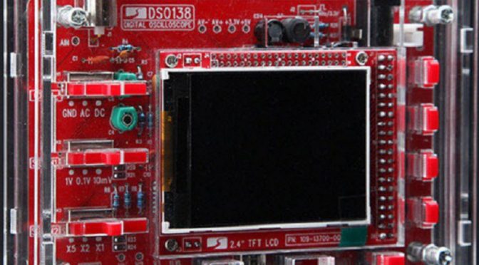
Back by popular demand (and good reviews from others) is our kit building night. Everyone had a blast on Election Night building the Pixie kits, and on V-day, we are going to work on a DIY oscilloscope known as the DSO138. (It is mere coincidence FYI that our kit building nights have fallen on holidays, of sorts).
The nice thing about this kit, of course, is being able to visualize some of the basic waveforms used in electronics. The kit does come with a square-wave test signal, but we will also have a signal generator present to visualize more complicated waveform.
Building this kit is an excellent opportunity to hone those soldering skills, brush up on electronics theory, and add another fun toy to your growing (or perhaps overflowing) collection. The price point is definitely fair for an oscilloscope and may help you figure out if you’ll want a more sophisticated one down the road.
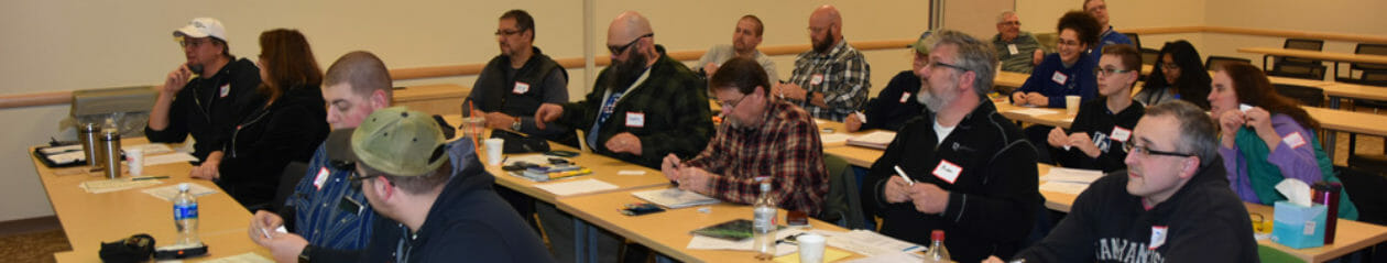
We had about 15 people last time, so I think this time, it’d be great to expand that number to 20 (or more)! Buy a kit here, and join us in February! Looking forward to seeing you.
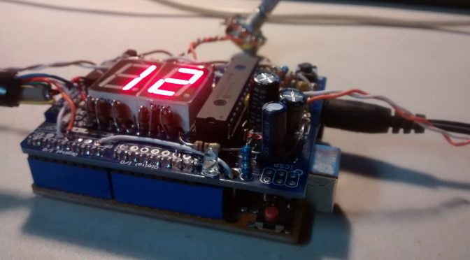
Below is my Arduino based CW iambic keyer. I wanted to be able to change my WPM on the fly using a potentiometer.
I had some LED 7 segment displays that would be perfect for this application. The issue then becomes how do I not use up all of my IOs… Below is the IC that I used.
Microchip Technology MCP23017-E/SP
This IC is much cheaper than a multiplexing IC for 8 digits.
Now I have plenty of IOs left over for buttons to Call CQ, give my callsign, and QTH etc.
If I wanted, I can keep adding more ICs (up to 8 total or 128 IOs!!) as needed just as long as I set a new unique address to each IC when using I2C.
I have also used this IC with an LCD display that uses up IOs quickly.
Let me begin by setting the scene. Imagine bone-chilling cold…It was colder. I was going to wait outside for Fred (AB1OC) and Jamey (KC1ENX) but the biology supporting my internal survival mechanism had other plans.
Bravely, I opened the door and was quickly greeted by John Bottoms. Interesting name, but a cool guy. We chatted for a bit and it turns out he’s working on embedding AI into VR…I think I have that right. He quickly pointed out that Thursdays are MakeIt Labs (see their web site) busy days since that is when they host their open house. I did see all around me many people working viciously on their projects. Truly, it was maker heaven.
Not long after, Fred and Jamey showed up and we were ready to begin our tour. Well, almost ready. There was a brief, but awkward exchange among two of the volunteers about who would be giving the tour. I was starting to wonder why it was so long and drawn-out. Odor-eaters in my shoes? (Check), Deodorant applied? (Check)…so it couldn’t be me. Eventually, the two fellas realized a better alternative to suit both their agendas was to elicit the help of a 3rd fellow. That fellow was Doug; he’s good people.
Machine Lathe
Doug began by taking us into the garage. Man, you all have to see this place. Woodworking shops, machine shops (including lathes and CNC machines), a litany of other heavy power tools to make the biggest kid drool), a plasma cutting machine, a mechanic’s shop to bring your vehicle to tune it up — change the oil — or add nitrous. This. Place. Was. Awesome.
CNC Plasma Cutting Table
Fred was definitely familiar with the tools and instruments there. Jamey and I looked awed but bewildered. During our combined awe-strike, Fred found himself in a conversation with another knowledgeable gentleman named Andrew about plasma cutting through steel. It began harmless enough. They were telling each other about the thickest piece of steel they ever cut through. But soon, you could tell the other could not be outdone. By the end of it, I swore I heard tall-tales of karate chopping through 4 ft. titanium able to withstand a nuclear strike. All pretty cool stuff. (I may have embellished a little)
CNC Vertical Milling Machine
We continued the tour to the electronics portion of the lab where they had 3D printers (and another one in color), a spare electronics parts room, networking stations, dudes flying around mini-drones. We also saw they had a fabric station where folks could come in to sew. I was surprised there wasn’t a line for this. Making blankets seems like the right thing to do currently.
CNC Laser Cutter
We saw multiple conference rooms available, a room for the FIRST robotics team they adopted, office space for folks with start-up companies — something for everyone.
Laser Cut Wood and Polystyrene Projects
By the conclusion of the tour, we got to meet a member of their Board, Bill. (Hi Bill!) This guy was definitely on board with bringing amateur radio to the masses. He liked our ideas of setting up for Kid’s Day (or some variant of it), of our near-space balloon project, teaching license classes and/or intro. to amateur radio courses, and even helping us advertise before we arrive. I think he saw the strong parallels between what they do and what we do. This could truly begin to be a very useful symbiotic relationship.
So with our visit over, I would recommend to those of you who have not had the pleasure, get yourself out to MakeIt Labs. If you have questions, please contact me, Jamey, or Fred. (Fred became a member tonight, so he knows the secret handshake). I think if you have ideas, projects that you’ve always meant to get done but haven’t found the time yet — this is the place for you. I think after you see this place, and if you were on the fence about getting involved in the Club’s Youth Outreach effort, I think you’re going to be all in after visiting.
We use cookies to ensure that we give you the best experience on our website. If you continue to use this site we will assume that you are happy with it.