Introduction
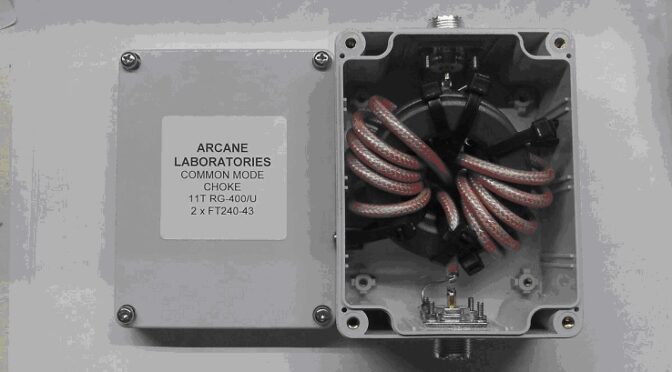
In Part I of this three-part series, we discuss what is meant by differential and common modes on RF transmission lines. Part II will discuss the construction of the Joe Reisert, W1JR, 1:1 balun [1] that may also be used as a common mode choke. Part III will present some test results for the common mode rejection of two common mode chokes, one constructed with #31 ferrite material and another constructed with #43 ferrite material.
Differential Mode
Two familiar balanced transmission line types that will support differential mode operation are open wire line and waveguide. This section will focus on open-wire lines. An ideal model of an open-wire line is shown in Figure 1. Current from the transmitter or other matched source enters the transmission line from the left. The transmission line may be thought of as an infinite number of distributed inductors and capacitors. Each infinitesimal length of the transmission line is made up of two tiny inductors, and each infinitesimal pair of lines forms a capacitor between them. All transmission line types, not only open wire lines, are characterized by values for inductance per unit length and capacitance per unit length.
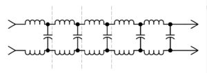
Figure 1 Idealized Model of Open Wire Transmission Line. An open wire transmission may be modeled as an infinite number of distributed inductors and capacitors.
In reality, the conductors will have a resistance per unit length. If there is a dielectric present, as there might be in a window line, twin-lead or open wire line (the dielectric would be the spreaders and air), there will also be a leakage conductance through the dielectric between the conductors.
Consequently, all transmission lines are characterized by an impedance, Z0, that is defined by,

where,
Z0 is the characteristic impedance in ohms
R is the resistance of the wire per unit length
G is the leakage conductance through the dielectric per unit length
L is the inductance of the transmission line per unit length
C is the capacitance of the transmission line per unit length.
Years ago, it was quite common for roof-mounted television antennas to be fed with 300-ohm twin-lead. Twinlead is a parallel wire transmission line in which the conductors are spaced apart with plastic dielectric. The dielectric fills very little of the volume around the conductors. There is just enough plastic to cover the conductors and space them a small distance apart. Consequently, twin-lead will be treated as though it were an open-wire line. If we assume that the resistance of the wire and the leakage conductance are negligible, we can make the approximations that,

As a result, the impedance of the transmission line may be simplified to,

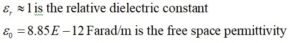
By making further approximations that the wire diameter, d, is much smaller than the center-to-center spacing of the conductors, D, and that the value of the dielectric constant filling the volume around the conductors is close to unity,

it is possible to approximate the values of L and C from,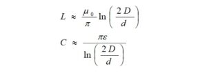
where,
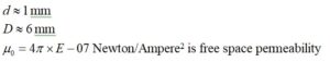
and,

where,
from which we get,
Furthermore,

Thus,

Substituting the numerical values, we have,

So, by making reasonable approximations, our estimate is very close to 300 ohms.
When driven by and terminated in its real, characteristic impedance, the currents and voltages anywhere along the open wire transmission line will be mostly uniform. Assuming that the wire transmission line is well made, dissipative losses in the conductors and leakage conductance will account for any nonuniformity. Since the currents in the transmission line conductors are equal and travel in opposite directions, the transmission line is said to be operating in differential mode. Simply stated, the transmission line operates in a single mode, and what you put in one end is mostly what you get out of the other end. The transmission line will not radiate signals, nor will it receive signals and noise.
Figure 2 is greatly oversimplified, but it is adequate to explain what is meant by differential mode. We note that if we take a snapshot of the currents on each half of the dipole, i1, and i2, they are in the same direction as are the currents, i1 and i2, in the open wire transmission line. From this, we may conclude that the transmission line is operating in differential mode while the antenna is operating in common mode, and that is what is causing the antenna to radiate RF in the first place. At least for this case, we have demonstrated that we may associate common mode currents with antenna radiation (and reception, too).
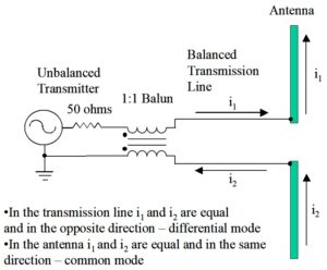
Figure 2. Balanced Open Wire Transmission Line Feeds a Dipole Antenna. The unbalanced transmitter or transceiver is transformed to a balanced transmission line with a balun. The transmission line operates in a single, differential mode because the currents are opposite while the antenna operates in a common mode because the currents are in the same direction.
Common Mode
For completeness, let’s begin by calculating the characteristic impedance of an unbalanced coaxial transmission line. Coaxial cable was first employed to prevent interference between transmission lines in transatlantic cables used for telegraphy prior to 1860. It was Oliver Heaviside who first described its theory of operation.
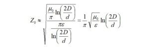
Let’s determine the characteristic impedance of RG-400/U since our common mode chokes were constructed using this type of coax. RG-400/U was chosen because of its high power handling capability and small outer diameter. If the inner diameter of the coax shield is much greater than the diameter of the center conductor,

where,
d is the diameter of the coaxial transmission line center conductor
D is the inner diameter of the coaxial transmission line shield,
the inductance per unit length and capacitance per unit length for coaxial cable are approximated by the formulas,

where,
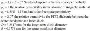
from which we obtain,
As before,
Substituting the numerical values, we have,
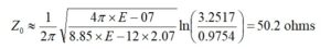
Again, reasonable assumptions lead us to the expected result.
When we speak of common mode for transmission lines, we are discussing signals that may enter or leave the conductors in the same direction. The most common cause of common mode current is an unbalanced transmission line. Imagine, if you would, a dipole antenna being fed by the coaxial transmission line of Figure 3. The currents inside the coax will be opposite. Now, suppose that the currents in the coax reach the antenna. If we take a snapshot of the currents on each half of the dipole, i4, and i2, they correspond to the directions of the currents, i3, and i1, on the inside of the transmission line (but not their amplitudes). From this, we may conclude from the currents on the antenna that the antenna operates in common mode, as before.
However, we also notice that there are currents, i5, on the outside of the coax shield and the current, i1, on the center conductor that are in the same direction. These currents operate in common mode. The outside of the coaxial cable shield operates as a single conductor transmission line, a distinct mode. This mode operates separately from the mode represented by currents i3 and i1, which operate in, essentially, differential mode. Thus, we have a transmission line system that operates in two distinct modes. The outer cable shield will radiate upon transmit and will be susceptible to receiving signals and noise upon receive.
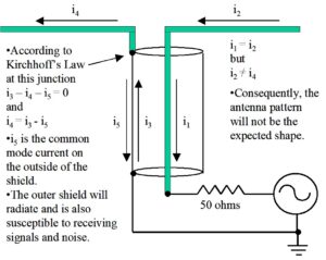
Figure 3. Common Mode Currents on Unbalanced Coaxial Transmission Line. Because of its construction, there is no way to keep the current i3 from dividing into currents i4 and i5. Since currents i1 and i5 are in the same direction, they operate in common mode. Since the currents i1 and i3 are in opposite directions, they operate in differential mode. Thus, we have a transmission line system that operates in two distinct modes. The common mode conductor will radiate and also be susceptible to receiving signals and noise.
To reiterate, since one side of our dipole antenna is connected to the shield, any current that is traveling inside the shield may split between the antenna and the outside of the shield. In this configuration, there is nothing to stop this from happening. Now, we have a center conductor and the outside of the shield acting like a pair of conductors with currents traveling in the same direction. This is very much like a single wire transmission line, and the outer shield will radiate and receive power quite nicely in common mode. Another observation is that the currents on the antenna halves are asymmetric, and this asymmetry will corrupt the antenna pattern. Notice that the current on the outer shield may be returned to the chassis of the transmitter. This can become very unpleasant for the operator.
A remedy for this is to convert the unbalanced coaxial line to a balanced line where it feeds the antenna and provides a means to suppress current i5. This is done with a device called a choke balun (balanced-to-unbalanced). The choke balun effectively disconnects the inner shield from the outer shield so that most of the current will no longer flow on the outer shield. Can there still be common mode currents on the coax? The answer is yes. The shield can still couple some of the antenna’s radiated emission back to the shack, or signals and noise on the shield may originate from elsewhere. Either or both may occur because it’s not unusual to place a choke balun at the feedpoint of the antenna. RF can still couple to the coax beyond where the choke is located. For this reason, it is not unusual to place another choke at another current maximum on the coax outer shield where it may be effective and at a location that is close to the entrance to the shack. This point on the transmission line may be found with a clip-on antenna current probe like the MFJ-854 [2], or by modeling the antenna in something like EZNEC [3]. It is incorrect to assume that the placement of a common mode choke is arbitrary. If we want the common mode choke to work, it should be located near a voltage null on the outside coax shield. Another effective way to reduce the common mode signals and noise on the outer shield from reaching the shack is to bury at least some of the coax.
Baluns may be constructed from sections of coax or from wire or coax wrapped on ferrite cores. Baluns constructed from coax alone, rely upon the electrical length of the coax to work, so they tend to be narrow band. Baluns constructed from coax are more practical for UHF and VHF because of the short length of transmission line required. Coax baluns do not possess the same choking properties that ferrite baluns have.
Part II of this three-part series will discuss the construction of a Joe Reisert, W1JR, 1:1 balun that may also be used as a common mode choke.
References
- Reisert, Joe, Simple and Efficient Broadband Balun, Ham Radio, September 1978, pp. 12-15. https://worldradiohistory.com/Archive-DX/Ham Radio/70s/Ham-Radio-197809.pdf
- https://mfjenterprises.com/products/mfj-854
- https://www.eznec.com/