All posts by Martin Blustine

I studied physics and went on to work in infrared optics, millimeter wave and microwave engineering until retirement. My interests lie in teaching, music, radio astronomy, infrared systems and microwave and antenna engineering. I enjoy writing technical papers about ham radio topics. When I am not operating CW, I enjoy homebrewing ham gear and restoring vintage HP and Agilent test and measurement equipment.

Differential and Common Modes on Transmission Lines – Part I

Introduction

In Part I of this three-part series, we discuss what is meant by differential and common modes on RF transmission lines. Part II will discuss the construction of the Joe Reisert, W1JR, 1:1 balun [1] that may also be used as a common mode choke. Part III will present some test results for the common mode rejection of two common mode chokes, one constructed with #31 ferrite material and another constructed with #43 ferrite material.

Differential Mode

Two familiar balanced transmission line types that will support differential mode operation are open wire line and waveguide. This section will focus on open-wire lines. An ideal model of an open-wire line is shown in Figure 1. Current from the transmitter or other matched source enters the transmission line from the left. The transmission line may be thought of as an infinite number of distributed inductors and capacitors. Each infinitesimal length of the transmission line is made up of two tiny inductors, and each infinitesimal pair of lines forms a capacitor between them. All transmission line types, not only open wire lines, are characterized by values for inductance per unit length and capacitance per unit length.
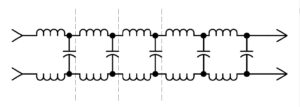
Figure 1 Idealized Model of Open Wire Transmission Line. An open wire transmission may be modeled as an infinite number of distributed inductors and capacitors.

In reality, the conductors will have a resistance per unit length. If there is a dielectric present, as there might be in a window line, twin-lead or open wire line (the dielectric would be the spreaders and air), there will also be a leakage conductance through the dielectric between the conductors.

Consequently, all transmission lines are characterized by an impedance, Z0, that is defined by,

where,

Z0 is the characteristic impedance in ohms

R is the resistance of the wire per unit length

G is the leakage conductance through the dielectric per unit length

L is the inductance of the transmission line per unit length

C is the capacitance of the transmission line per unit length.

Years ago, it was quite common for roof-mounted television antennas to be fed with 300-ohm twin-lead. Twinlead is a parallel wire transmission line in which the conductors are spaced apart with plastic dielectric. The dielectric fills very little of the volume around the conductors. There is just enough plastic to cover the conductors and space them a small distance apart. Consequently, twin-lead will be treated as though it were an open-wire line. If we assume that the resistance of the wire and the leakage conductance are negligible, we can make the approximations that,

As a result, the impedance of the transmission line may be simplified to,

By making further approximations that the wire diameter, d, is much smaller than the center-to-center spacing of the conductors, D, and that the value of the dielectric constant filling the volume around the conductors is close to unity,

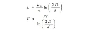
it is possible to approximate the values of L and C from,
where,

and,

where,

from which we get,
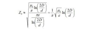
Furthermore,

Thus,

Substituting the numerical values, we have,

So, by making reasonable approximations, our estimate is very close to 300 ohms.

When driven by and terminated in its real, characteristic impedance, the currents and voltages anywhere along the open wire transmission line will be mostly uniform. Assuming that the wire transmission line is well made, dissipative losses in the conductors and leakage conductance will account for any nonuniformity. Since the currents in the transmission line conductors are equal and travel in opposite directions, the transmission line is said to be operating in differential mode. Simply stated, the transmission line operates in a single mode, and what you put in one end is mostly what you get out of the other end. The transmission line will not radiate signals, nor will it receive signals and noise.

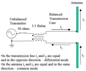
Figure 2 is greatly oversimplified, but it is adequate to explain what is meant by differential mode. We note that if we take a snapshot of the currents on each half of the dipole, i1, and i2, they are in the same direction as are the currents, i1 and i2, in the open wire transmission line. From this, we may conclude that the transmission line is operating in differential mode while the antenna is operating in common mode, and that is what is causing the antenna to radiate RF in the first place. At least for this case, we have demonstrated that we may associate common mode currents with antenna radiation (and reception, too).
Transmission Lines

Figure 2. Balanced Open Wire Transmission Line Feeds a Dipole Antenna. The unbalanced transmitter or transceiver is transformed to a balanced transmission line with a balun. The transmission line operates in a single, differential mode because the currents are opposite while the antenna operates in a common mode because the currents are in the same direction.

Common Mode

For completeness, let’s begin by calculating the characteristic impedance of an unbalanced coaxial transmission line. Coaxial cable was first employed to prevent interference between transmission lines in transatlantic cables used for telegraphy prior to 1860. It was Oliver Heaviside who first described its theory of operation.

Let’s determine the characteristic impedance of RG-400/U since our common mode chokes were constructed using this type of coax. RG-400/U was chosen because of its high power handling capability and small outer diameter. If the inner diameter of the coax shield is much greater than the diameter of the center conductor,

where,

d is the diameter of the coaxial transmission line center conductor
D is the inner diameter of the coaxial transmission line shield,

the inductance per unit length and capacitance per unit length for coaxial cable are approximated by the formulas,

where,
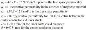
from which we obtain,

As before,

Substituting the numerical values, we have,

Again, reasonable assumptions lead us to the expected result.

When we speak of common mode for transmission lines, we are discussing signals that may enter or leave the conductors in the same direction. The most common cause of common mode current is an unbalanced transmission line. Imagine, if you would, a dipole antenna being fed by the coaxial transmission line of Figure 3. The currents inside the coax will be opposite. Now, suppose that the currents in the coax reach the antenna. If we take a snapshot of the currents on each half of the dipole, i4, and i2, they correspond to the directions of the currents, i3, and i1, on the inside of the transmission line (but not their amplitudes). From this, we may conclude from the currents on the antenna that the antenna operates in common mode, as before.

However, we also notice that there are currents, i5, on the outside of the coax shield and the current, i1, on the center conductor that are in the same direction. These currents operate in common mode. The outside of the coaxial cable shield operates as a single conductor transmission line, a distinct mode. This mode operates separately from the mode represented by currents i3 and i1, which operate in, essentially, differential mode. Thus, we have a transmission line system that operates in two distinct modes. The outer cable shield will radiate upon transmit and will be susceptible to receiving signals and noise upon receive.
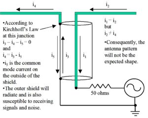
Figure 3. Common Mode Currents on Unbalanced Coaxial Transmission Line. Because of its construction, there is no way to keep the current i3 from dividing into currents i4 and i5. Since currents i1 and i5 are in the same direction, they operate in common mode. Since the currents i1 and i3 are in opposite directions, they operate in differential mode. Thus, we have a transmission line system that operates in two distinct modes. The common mode conductor will radiate and also be susceptible to receiving signals and noise.

To reiterate, since one side of our dipole antenna is connected to the shield, any current that is traveling inside the shield may split between the antenna and the outside of the shield. In this configuration, there is nothing to stop this from happening. Now, we have a center conductor and the outside of the shield acting like a pair of conductors with currents traveling in the same direction. This is very much like a single wire transmission line, and the outer shield will radiate and receive power quite nicely in common mode. Another observation is that the currents on the antenna halves are asymmetric, and this asymmetry will corrupt the antenna pattern. Notice that the current on the outer shield may be returned to the chassis of the transmitter. This can become very unpleasant for the operator.

A remedy for this is to convert the unbalanced coaxial line to a balanced line where it feeds the antenna and provides a means to suppress current i5. This is done with a device called a choke balun (balanced-to-unbalanced). The choke balun effectively disconnects the inner shield from the outer shield so that most of the current will no longer flow on the outer shield. Can there still be common mode currents on the coax? The answer is yes. The shield can still couple some of the antenna’s radiated emission back to the shack, or signals and noise on the shield may originate from elsewhere. Either or both may occur because it’s not unusual to place a choke balun at the feedpoint of the antenna. RF can still couple to the coax beyond where the choke is located. For this reason, it is not unusual to place another choke at another current maximum on the coax outer shield where it may be effective and at a location that is close to the entrance to the shack. This point on the transmission line may be found with a clip-on antenna current probe like the MFJ-854 [2], or by modeling the antenna in something like EZNEC [3]. It is incorrect to assume that the placement of a common mode choke is arbitrary. If we want the common mode choke to work, it should be located near a voltage null on the outside coax shield. Another effective way to reduce the common mode signals and noise on the outer shield from reaching the shack is to bury at least some of the coax.

Baluns may be constructed from sections of coax or from wire or coax wrapped on ferrite cores. Baluns constructed from coax alone, rely upon the electrical length of the coax to work, so they tend to be narrow band. Baluns constructed from coax are more practical for UHF and VHF because of the short length of transmission line required. Coax baluns do not possess the same choking properties that ferrite baluns have.

Part II of this three-part series will discuss the construction of a Joe Reisert, W1JR, 1:1 balun that may also be used as a common mode choke.

References

  1. Reisert, Joe, Simple and Efficient Broadband Balun, Ham Radio, September 1978, pp. 12-15. https://worldradiohistory.com/Archive-DX/Ham Radio/70s/Ham-Radio-197809.pdf
  2. https://mfjenterprises.com/products/mfj-854
  3. https://www.eznec.com/

Control Your Rig Remotely With This USB-Controlled Power Station

Introduction

Remote station operation has become more popular now that several rig manufacturers offer accessories to enable the radio amateur to do so. However, there is usually a large expense associated with acquiring these accessories. For some, it may not be cost-effective to own them for occasional use. In this article, we describe a solution for remote operation from another room of your home, your yard, or while on travel. It is also convenient for controlling on/off functions in the shack with the click of the mouse. The solution revolves around a Velleman relay card that can control a number of relays from a computer desktop.

The Power Station

This article describes a USB-controlled AC power strip, Figure 1, that was built around the Velleman K8090 8-Channel Relay Board in kit-form [1]. Varistors were added to the board as a recommended option [2]. The board can also be purchased fully assembled [3].

Figure 1. USB Controlled Power Strip. Each 15A duplex outlet is under USB control. There are just enough contacts on the barrier strip for 8 relays, neutrals, and grounds.

The PC communicates to the board via USB. A free, desktop, graphical user interface (GUI) is provided by Velleman for use as test software, or you may opt to purchase an application such as N-Button Lite [4].

Some type of rig interface is required to control your rig and audio from a PC. You may use the interface in your rig if it has one, or buy or build one of your own.

In order to log onto your computer, see your desktop remotely and hear rig audio, some kind of conferencing software is required. I use TeamViewer [5] to see my desktop and hear computer audio remotely.

Cautionary Notes

You will be dealing with AC line voltage in this project. Keep the clear polycarbonate cover on the enclosure while AC power is applied. Since the Velleman card operates on 12 VDC and control is over USB, all testing can be completed prior to plugging the AC line cord into the wall socket.

The FCC requires some means to disable the transmitter within 3-minutes if something goes wrong during remote operation. Velleman makes a WMT1206 Universal Timer Module with USB Interface [6] that should prove useful for this application. Its relay can handle 8A of AC. There are also similar USB timer modules available on eBay. It’s also a good idea to have the ability to reboot your computer remotely. The exact details of how to implement this FCC requirement are left to the reader but there are plenty of suggestions to be found online.

Kit Construction

An experienced kit builder can assemble and test the board in an afternoon. The added varistors are specified at 125J, 300VAC, 385VDC, and 4500A clamping peak current [7]. If these are not readily available, there are equivalents. A suggestion was made to thicken the circuit board traces that must handle the 16A relay current with additional solder. I didn’t care for this approach and opted to solder bus wire onto these traces, instead. You might find it ludicrous to solder #14 AWG buss wire onto the board, so your other option is to derate the relay capabilities to what the conductors can safely handle since the PCB traces have not been rated. For example, the ampacity of #20 AWG buss wire is at least 5A (11A at 75°C) [8], and that will be good for 575W. None of the circuits that I run from this PCB require anywhere near 575W.  Take care not to damage the PCB traces while soldering. Excessive heat will lift the PCB traces.

Housing, Connectors, and AC Outlets

There are 8 duplex outlets in this project – each one under separate relay control. Each outlet has been wired with #14 AWG. Each relay is rated at 16A, resistive load (see the previous section for derating). The duplex outlets have been spaced far apart so that a variety of line cords and wall adapters will fit without interference. The control board is housed in a Bud Industries PN-1340-C polycarbonate enclosure [9] with a clear cover (not affixed), Figure 2. The clear cover provides visibility for the status lights on the PCB. Bud Industries also manufactures an internal aluminum panel, PNX-91440 [10], upon which the PCB and barrier strip have been mounted. Take care in locating connectors on the housing or the PCB will not fit. The PCB is fastened to the aluminum panel with 4-40 hex standoffs. The Bud Industries enclosure is fitted with 1/2-inch male terminal adapters [11] at either end. DC power for the relays enters the enclosure at the top left through a 2.1mm panel mount connector [12]. The relay power required is 12VDC at 400mA. A 12 VDC wall adapter with a 2.1mm plug can provide this voltage. AC power enters the housing through a cable gland at the lower left. Switchcraft makes the USB connector at the lower right. It converts USB A inside the enclosure to USB B on the outside. The connector was purchased from Newark [13]. The short USB jumper patch cord was purchased on Amazon [14]. A step drill [15] is the most effective way to bore the large holes in a polycarbonate or ABS case without cracking it.

Remote Control

Figure 2. Interior View of Control Board Enclosure. Eight 16A relays are visible. There’s not much space to spare. Take care in wiring the AC connections and in locating the connectors on the housing or the PCB will not fit.

Software Apps

The test software that is supplied by Velleman for the circuit card is adequate, or N-Button Lite [16] may be purchased Figure 3. A screenshot of the lower right corner of the monitor shows the buttons for N-Button Lite. The green buttons indicate that four of the eight relays are active. If you purchase the Bud enclosure with a clear polycarbonate cover as I did, you will be able to see all eight red indicator lights on the Velleman board, one for each relay. They will light when a relay becomes active.

Remote Control

Figure 3. Screenshot of PC desktop. N-Button Lite controls each of 8 relays.

References

References
[1] https://www.jameco.com/z/K8090-Velleman-8-Channel-USB-Relay-Card-Kit_2123952.html
[2] https://www.velleman.eu/products/spareparts/?code=vdr300
[3] https://www.amazon.com/Velleman-VM8090-8-Channel-Relay-Card/dp/B00CPCQ88Y
[4] https://www.serialporttool.com/GK/n-button-lite/
[5] https://www.teamviewer.com/en-us/?utm_source=google&utm_medium=cpc&utm_campaign=us|b|pr|19|jul|Brand-TeamViewer-Exact|free|t0|0|dl|g&utm_content=TeamViewer_Exact&utm_term=teamviewer&gclid=Cj0KCQjw5ZSWBhCVARIsALERCvzZflNoCfAiFgi9STEIDiJkCtRuazuukru
[6] https://whadda.com/product/universal-timer-module-with-usb-interface-wmt206/
[7] Velleman, op. cit. https://www.velleman.eu/products/spareparts/?code=vdr300
[8] https://en.wikipedia.org/wiki/American_wire_gauge
[9] https://www.budind.com/product/nema-ip-rated-boxes/pn-series-nema-box/ip65-nema-4x-box-with-clear-cover-pn-1340-c/ – group=series-products&external_dimension
[10] https://www.budind.com/accessories/aluminum-internal-panel-pnx-91440/
[11]https://www.homedepot.com/p/1-2-in-Male-Terminal-Adapter-R5140103/202043509
[12] https://www.amazon.com/2-1mm-DC-Power-Jack-Chassis/dp/B073PKZPQ7
[13] https://www.newark.com/switchcraft-conxall/ehusbbabxpkg/usb-adapter-type-b-rcpt-a-rcpt/dp/08N9043?gclid=Cj0KCQjw5ZSWBhCVARIsALERCvycmWj-i38ykHaPrlbG8Eb-uxCyxcpZzdNWmZ0r7Z2iV9zgd7CpVKAaAh5KEALw_wcB&mckv=_dc|pcrid||plid||kword||match||slid||product|
[14] https://www.amazon.com/inch-USB-2-0-Male-Cable/dp/B079ZP65SN?th=1
[15] https://www.homedepot.com/s/step%2520drill?NCNI-5
[16] Relay Pros, op. cit. https://www.serialporttool.com/GK/n-button-lite/

Tilt-Over Bases for Antenna Masts That You Can Build

Introduction

Most of us have installed temporary antenna masts and have looked for a way to raise, lower and guy the masts while working alone. This was the case when I wanted to raise three masts for temporary antenna testing. When I couldn’t find any tilt-over bases that were sturdy, I decided to design and build some of my own from readily available materials.

I wanted mast bases that were rugged and heavy, not thin and flimsy. I discovered that mild steel [1] with its high carbon content is easy to weld, so I settled on that material. I also found a source for mild steel hinges [2]. They were perfect matches for mild steel plate. (In case you prefer aluminum, heliarc welding has become routine. It all depends upon what the welder quotes for a price and how heavy you want the bases to be.)

A sketch of what was built appears in Figure 1. All of the dimensions are based upon available materials. The only cutting required was to fabricate a steel shim [3]. When the tilt-over base is in its upright position, this shim, which is the same thickness as the hinges, maintains the spacing between the steel plates.

tilt-over bases

Figure 1. Design Sketch. The small holes in the left base plate accommodate 3/8” spikes (see text). The steel tube is welded to the rear side of the right top plate (see text).

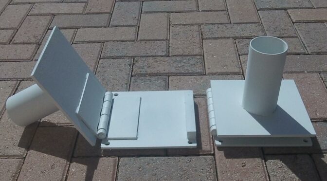
A local welder assembled three tilt-over base mounts from supplied 8″ x 8″ x 1/4″ mild steel plate, 3″ OD 11 gauge steel tube, 6″ x 6″ steel hinges, and 3/4″ x 3/4″ x 6″ steel bar stock. The steel plate, hinges and bar stock were ordered from Amazon, while the tubing [4] was ordered from Coremark. The ID of the base tube is 2.75″ (70mm), 11ga. This is a loose fit for the cap at the bottom of most fiberglass masts. I used felt blankets [5] as shims for a tighter fit and to protect the masts. The base mounts are anchored to the ground with 3/8″ x 12″ galvanized spikes [6]. Four ½” holes drilled in the bottom plate for this purpose are visible. The spikes prevent the bases from sliding while the masts are being raised and lowered.

Once welded, the welding flux should be removed. Since high carbon steel will rust, the welded assemblies were cleaned and prepped with phosphoric acid [7] and steel wool before priming with spray metal primer [8]. The primed bases were spray-painted [9]. The finished product is shown in Figure 2.

tilt-over bases

Figure 2. Tilt-Over Bases. These tilt-over mast bases are sturdy and stable when anchored to the ground with 3/8″ x 12” galvanized spikes. The tilt-over feature makes it easy to raise and lower portable telescoping and non-telescoping masts while working alone.

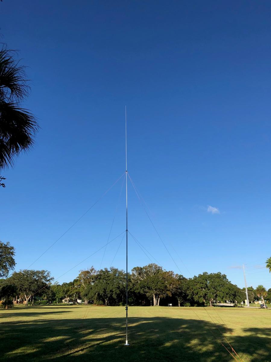
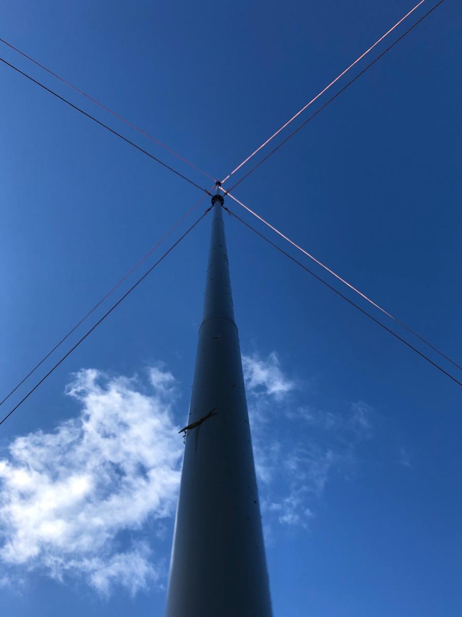
A typical installation is shown in Figure 3. The 33’ (10m) masts shown were guyed at two levels with guy rings. Four Dacron paracord guy ropes were used on each guy ring. Fluorescent orange paracords were used for enhanced visibility. Temporary ground anchoring is accomplished with polycarbonate Orange Screws [10] as shown in Figure 4. Taut-line hitches are used to tighten the guying ropes – a useful knot to remember.

The mast is raised with two lower guy ropes in place. The ropes are adjusted to hold the mast a few degrees past vertical until the final two lower guy ropes are placed. Finally, the upper four guy ropes are placed.

Figure 3. Typical Installation. Guying is performed at two levels. The mast is raised while working alone with two lower guy ropes in place. The ropes are adjusted to hold the mast a few degrees past vertical until the final two lower guy ropes are placed. Finally, the upper four guy ropes are set. A post level, visible on the mast, is used to true it up. Photo courtesy of N4UM.

Figure 4. Guy view. The masts are guyed at two levels. Eight Dacron paracord ropes are used. The paracords are fastened to the guy rings with snap hooks. Tensioning is adjusted with taut-line hitches. Photo courtesy of N4UM.

Figure 5. Orange Screw Ground Anchors. The guy ropes are adjusted with taut-line hitches. During antenna range testing, the Orange Screws were set in sandy soil. Three masts remained standing during two weeks of rain and stiff winds.

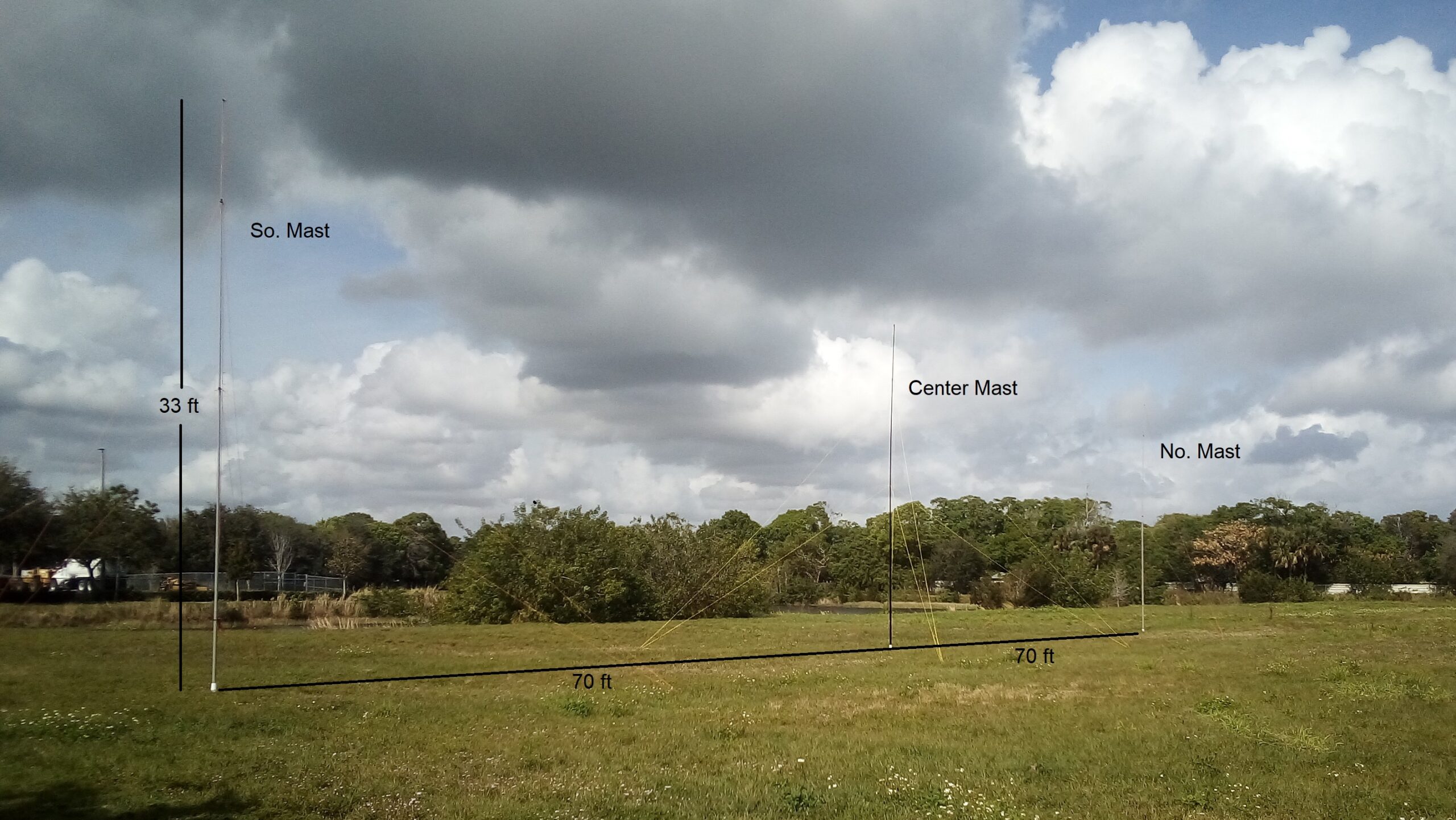
Figure 6. Antenna Range with 3 Tilt-Over Bases in Use. An antenna range was constructed with three fiberglass masts and tilt-over bases. The dimensions of the range are as pictured. This 140’ range was left unattended during 2 weeks of Florida spring wind and rain. Note that paracord back-guys were employed at the very tops of the north and south masts to relieve the lateral loading due to the weight of the wire. Without back-guying, the top sections of the telescoping masts are apt to snap off.

References*

[1]https://www.amazon.com/s?k=8+x+8+x+1%2F4+steel+plate&crid=188CJTXB7VM3W&sprefix=8+x+8+x+1%2F4+steel+plate%2Caps%2C585&ref=nb_sb_noss_2
[2]https://www.amazon.com/Hinge-Weld-Heavy-Metal-Doors/dp/B0821HQQSJ/ref=sr_1_5?crid=3UEBPDTTXJFF8&keywords=6%22%2Bsteel%2Bhinges&qid=1656544819&sprefix=6%2Bsteel%2Bi%2Caps%2C107&sr=8-5&th=1
[3]https://www.amazon.com/1018-Drawn-Steel-Square-Stock/dp/B09GY7MQ2V/ref=sr_1_3?crid=3DB0BOW75U320&keywords=3%2F4+steel+bar+stock&qid=1656544926&sprefix=3%2F4+steel+bar%2Caps%2C192&sr=8-3
[4]https://www.coremarkmetals.com/electric-welded-erw-round-steel-tube
[5]https://www.homedepot.com/p/Everbilt-2-in-x-4-in-Heavy-Duty-Self-Adhesive-Beige-Felt-Blanket-3-Pack-804614/306229475?
[6]https://www.lowes.com/pd/Grip-Rite-12-in-x-3-8-in-Spike/3610436
[7]https://www.homedepot.com/p/Klean-Strip-1-Gal-Concrete-Etch-Metal-Prep-and-Rust-Inhibitor-GKPA30220/100406369
[8]https://www.homedepot.com/p/Rust-Oleum-Stops-Rust-12-oz-Flat-White-Clean-Metal-Primer-Spray-7780830/100143442
[9]https://www.homedepot.com/p/Rust-Oleum-Stops-Rust-12-oz-Protective-Enamel-Semi-Gloss-White-Spray-Paint-7797830/205585926
[10]https://www.sportsmans.com/camping-gear-supplies/tents-shelters/tent-accessories/orange-screw-small-ground-anchor-4-pack/p/1531885?channel=shopping&gclid=Cj0KCQjw8O-VBhCpARIsACMvVLMO-RmVGrVvtXURmIiQcQRsAo_r91rbskWRWtAzqqAUniop6Wnm5QYaAutREALw_wcB
[11]https://www.amazon.com/Orange-Screw-Ultimate-Ground-Anchor/dp/B01D3UIA5A/ref=asc_df_B01D3UIA5A/?tag=hyprod-20&linkCode=df0&hvadid=167119746601&hvpos=&hvnetw=g&hvrand=17637355299886752168&hvpone=&hvptwo=&hvqmt=&hvdev=c&hvdvcmdl=&hvlocint=&hvlocphy=9002271&hvtargid=pla-307839372670&psc=1

*The references cite readily available sources of supply. You may be able to find lower prices for materials or substitutions elsewhere.

Radio Amateurs Developing Skills Worldwide