All posts by Fred Kemmerer

I enjoy station building, contesting and helping new folks to join and have fun with our hobby.

EME Station 2.0 Part 3 – Phase Tuned Receive Coax Cables

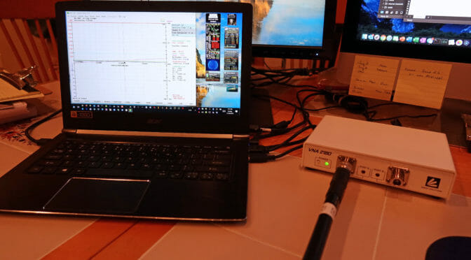
Our new 2M EME station will have Adaptive Polarity capability via MAP65. MAP65 requires that received signals from the Horizontal and Vertical planes of our antennas arrive at the receivers in our shack precisely in phase with each other. We used a VNA to precisely measure coax cable length…

Source: EME Station 2.0 Part 3 – Phase Tuned Receive Coax Cables

We are continuing to make progress on our new 2M EME Station. The MAP65 adaptive polarity aspect of our plans requires that the phase relationship between the Horizontal and Vertical elements of our antennas be precisely maintained by our receive coax cables.

The construction of these coax cables required us to use a Vector Network Analyzer (VNA) to precisely measure and equalize the electrical lengths of our receive-coax cables. We know that a 1/4 wavelength section of coax cable which has an open-circuit at one end will appear as a low (resonant) impedance at the opposite end. If we use a VNA to precisely measure the minium resonant frequency of our coax cables in this way, we can use a simple formula to determine the cables’ lengths.

The article associated with the link above explains how a VNA can be used to measure the length of a coax cable. A frequency accurate antenna analyzer can also be used to make these measurements.

Fred, AB1OC

EME Station 2.0 Part 2 – Excavation, Footings, and Conduits for New Tower

The first part of our EME project is to put up a new tower to support our antennas. Our plans call for a 26′ tower built using three Rohn 55G tower sections. Four feet of the first section of…

Source: EME Station 2.0 Part 2 – Excavation, Footings, and Conduits for New Tower

We are making some good progress on the construction of our 2m EME Station. We’ve completed the footings, base, conduits for a new 26′ tower.

EME Tower
FInished Tower Base

The link above explains what was involved in this stage of the construction. We’ll be completing our new tower in a few weeks.

Fred, AB1OC

EME Station 2.0 Part 1 – Goals and Station Design

EME or Earth-Moon-Earth contacts involve bouncing signals off the moon to make contacts. An EME station provides a means to make DX contacts using the VHF and higher bands. There are also some EME Contests in…

Source: EME Station 2.0 Part 1 – Goals and Station Design

We made some 2m EME contacts a while ago using the 2m antenna on our tower at about 112′. This experience created interest on my part in building a more capable EME station at some point in time. Well, the time has finally arrived.

2m EME Moon
A Four X-Polarized Yagi, 2m EME Antenna System

The article above explains our goals, plans, and design of a new 2m EME station at our QTH. The article covers plans for a new tower, antennas, and an SDR-based receive system.

Our plans are to build an 80th percentile station that utilizes four large, dual-polarity antennas in an array. The station will use the JT65 digital protocol and will support adaptive polarity via MAP65. The new setup will utilize WSJT and MAP65 software created for EME use by Joe Taylor.

Our plans are to begin construction of our new EME Station later this week with a new 26′ Rohn 55G tower going in first. You can read all about our plans via the link above.

Fred, AB1OC

Radio Amateurs Developing Skills Worldwide