
PART-1 A WSJT-X FT-8 Overview
The following is not meant to be an FT-8 manual. It is just the highlights to get started without breaking your radio or making on the air (OTA) enemies. A few of the operating suggestions are for those just starting out. Once you get beyond a few QSOs you will find some of the suggestions are nullified once more of the features are understood.
The basic functions and numerous features of WSJT-X can be found in the User Guide at https://physics.princeton.edu/pulsar/k1jt/wsjtx-doc/wsjtx-main-1.9.1.html, or by asking a NARS member familiar with WSJT-X, especially Fred Kemmerer (AB1OC) or Anita Kemmerer (AB1QB).
The real objective of this article is in PART-2 Why WSJT-X. Here I attempt to show the merits of the mode so many are calling the death of amateur radio as we know it. I see WSJT-X as a useful tool and an asset to Amateur Radio.
Getting Started
Having never touched an Amateur Radio Digital mode before I decided it was time. I spend a lot of time helping others get on the air and repairing their radios and saw requests for help setting up WSJT-X becoming more frequent. I’m also seeing an increase in radios used with digital modes with output device failures, especially older radios with BJTs for drivers and finals.
I needed to understand WSJT-X, its use is becoming wide spread.
In a recent presentation Joe Taylor, the JT in WSJT-X, presented Figure 1 based on data taken from 2017 ClubLog logs.
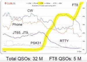
WSJT-X/FT-8 is becoming the mode of choice for many Hams where over 60% of the QSOs logged in December were FT-8. This is up from 0% in May 2017. The mode did not exist prior to Jun 2017.
To get started you only need three things:
- A newer radio with a USB interface and built-in sound card, or an external sound card like a SignaLink or RigBlaster for those radios without a built-in sound card.
- Any modest computer (Windows, iOS, or Linux) will work.
- WSJT-X which is a free download
There are additional programs that make syncing your computer’s clock and logging more convenient. I suggest you start with the 3 items above and become familiar with the mode before adding additional software.
Using a Kenwood TS-590SG it took less than 1 hour from downloading WSJT-X to my first FT-8 QSO. Most of the time was spent getting the COM port (CAT) and USB (Audio) settings in Windows, the radio’s menu settings, and WSJT-X on the same page.
I have since been through the process a number of times with a couple of IC-7300s, FT-991, TS-990 and using a SignaLink for the sound card, an FT-450D and a vintage Kenwood TS-140. (Note: you do not need SignaLink or similar if your radio has a USB/soundcard interface). The setup time has ranged from less than an hour to many hours in one case. The most difficult cases are where the radio’s USB cable was connected before the manufacture’s drivers were installed with MS Windows. Windows will pick a driver if the correct one is not available and it can be difficult to remove.
Some of the radio had quirks. For example on the Yaesu FT-991 setting the bandpass to 100Hz to 3 kHz in the menu isn’t sufficient, there is a separate menu item (NAR/WIDE) that must be set to Wide and with the TS-590SG to obtain a flat 0-3 kHz bandpass for TX and RX SSB (not SSB/Data) is used.
After my first FT-8 QSO and since I’m the first to admit I knew nothing about the mode and had a desire to practice good “on air” etiquette I spent time reading the WSJT-X user guide, forums, and other guides before my second QSO. Over the past month, I have added a large number of “new ones” to the log.
On the Air Etiquette
To understand the most important “etiquette” issues (or how to not be a bad neighbor) it is important to understand a little about the mode.
The basic setup is similar to SSB upper sideband (USB) as used for SSB Phone. (Note: SSB/USB is used on all WSJT-X modes, even 40m and longer). The difference between phone and FT-8 is instead of your voice producing tones that fill the entire 3 kHz channel as in SSB phone your information is coded into 8 audio tones separated by 6.25 Hz that only occupy 50 Hz of the 3 kHz channel. You may transmit the 50 Hz group of 8 tones “anywhere” from 300 Hz to 2,400 Hz. Notice we are talking Hz.
Let’s assume you choose 1,950 Hz to 2,000 Hz for you tone group. You can have a “neighbor” at 1,900 to 1,950 Hz and another at 2,000 to 2,050 Hz as well as over 40 over users throughout the rest of the 300 Hz to 2,400 Hz bandpass.
At the risk of being redundant Figure 2 presents the description in a graphic format. The graph is to scale, there are 40 plus FT-8 users in the same bandwidth as a typical SSB phone signal.
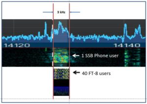
Both a single SSB phone user and 40 plus FT-8 users occupy about 3 kHz.
Just like SSB phone, overdriving the Radio with too much audio will cause splatter except with Phone you must have significant overdrive to splatter outside of a 3 kHz bandwidth and beyond a 3 kHz or so gap to the next occupied frequency. With FT-8 you have 50 Hz, and no gap to the next user, which demands a clean signal and very little spectrum growth. FT-8 is tolerant to signal overlap but at the cost of sensitivity.
Audio Drive
The audio drive level from the PC replaces the audio signal from a microphone. The level must be set with care or you will wipe out many users on both sides of your signal and your signal might not decode on receive. This is easily accomplished by reducing the audio drive to your radio from the PC or external sound card until the ALC level on transmit goes to almost zero and the output power starts to drop if you reduce the audio drive further.
RF Output Power
There are two reasons to reduce your transmit power.
First, another source of “splatter” is the harmonics and intermodulation products which increase as you approach the rated power output of your radio. for example, if your tone group is at 1 kHz its 2nd harmonic is in the FT-8 bandwidth at 2kHz. The same is true for intermodulation products that will occur at the tone spacing at N * 6.25 HZ on both sides of your tone group where N is 2 – 8.
The second reason to reduce RF output power is that digital modes like FT-8 are high duty cycle. FT-8 is 100% key down for 15 seconds every 15 seconds and JT-9 it’s a full minute. If you set the power at 100 watts the FT-8 output is 100 watts average, and also peak, for 15 seconds straight. For SSB phone or CW for most of us, it is about 40 watts average with occasional 100-watt peaks.
While older radios with BJT drivers and finals are more susceptible to thermal issues and failure LDMOS FETs have their limits as well. When running at high duty cycles at elevated output power the devices run very hot and their breakdown voltages are reduced. This is made worse if the output is into a high SWR antenna feedline.
Assuming a well-matched antenna 50 watts is a good maximum power when using the typical 100 watt HF radio for extended FT-8 operation while keeping adjacent channel interference to an acceptable level. I typically use 25 watts and have used 50 to 100 watts on occasion. For anything over 50 watts, I use an amplifier with the radio’s output attenuated down to 3 or 5 watts.
Low Power and Long Range
The noise floor of any radio is dependent on the bandwidth of the detection channel which is a very narrow 50 Hz for FT-8. In addition, FT-8 also benefits from processing gain and forward error correction. The end result is nearly a 31 dB advantage over SSB Phone as seen in Figure 3.

50 watts on FT-8 is roughly equivalent to 50 kW on SSB phone. WSJT waveforms were developed for earth moon earth (EME) and meteor scatter where the propagation losses are very high.
FT-8 is a weak signal mode and not a low power mode. With 50 watts you can “work the world” while keeping your radio reasonably cool and not interfering with adjacent users. Higher power is ok provided you manage adjacent channel interference and do not have thermal issues. Higher power is typically not required.
Figure-4 is an FT-8 waterfall; the scale across the top is Hz. The left edge is 0 Hz (i.e. the carrier). As it is SSB the carrier is suppressed. The green horizontal lines are 15 seconds apart. The TX and RX time slots can be seen in every other time slot.
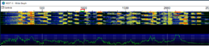
Since this is 40m the “dial frequency” per the band plan is 7,074 kHz. The FT-8 activity stops at 2,400 Hz. JT-9 is above 2,400 Hz, JT-9 users would not appreciate an FT-8 in their spectrum.
For clarity the receiver is tuned to 7,074* kHz, all of the users are at this freq plus the frequency of their modulating tones.
(* To compensate for receiver filter roll-off at the band edges 7,074 kHz may be shifted, for now, assume it is 7,074 kHz, WSJT-X is pre-configured for the correct frequencies in each band and has a feature to automatically shift this frequency if required. See the user manual for details)
The red “goal post” on the scale is my selected and locked Tx tone frequency of 950 Hz to 1000 Hz. The frequency over the air will be 7,074,950 Hz to 7,075,000 Hz. Note that it is in a quiet part of the received bandpass. It is important to learn how to select and lock your transmit frequency.
The green “goal post” is the FT-8 receive frequency, it can be set by the user but it is best to let the software set it automatically.
An overdriven signal can be seen on the waterfall at 350 Hz, note the vertical hash marks from 200 Hz to 500 Hz indicative of intermodulation products. This signal will probably not decode when received and it is impacting frequency slots for at least 6 adjacent users and possibly more at harmonics around 700 Hz and 2,100 Hz.
To wrap up etiquette:
– Set the audio drive level from the PC or sound card to the radio using transmit ALC levels to avoid splattering the band.
– Back off from the rated output of your radio to reduce spurious outputs and overheating or damaging the radio.
– Carefully select and lock your transmit frequency to avoid interfering with other local stations and being QRM’d on receive at the DX location. If your TX frequency is unlocked so you will be responding on a CQ callers frequency review the waterfall for possible conflicts.
If you take these steps you will make more contacts and fewer enemies.
Carefully select and lock your transmit frequency
Etiquette aside there are several reasons to carefully select and lock your transmit frequency. A lot of the fun is selecting a strategy for selecting time and frequency slots that quickly put a “new one” in the log.
If you do not lock the transmit frequency WSJT-X will set your transmit frequency to the frequency of the CQ you are answering. Everyone trying to respond to his CQ without a locked TX frequency will be on his frequency, QRMing each other. WSJT-X can separate overlapping signals to an extent, but not when everyone in the world is after a rare DX on his frequency slot. Everyone decodes all of the signals in the entire band. He will copy you anywhere in the 300-2,400 Hz bandpass unless there are strong local signals blocking him from copying you which bring us to the next point.
If you are unsuccessful in getting a response, move your TX frequency to another clear slot, you may find a spot where it is also clear on his end.
Once you become skilled at the basics there are times when it is best to unlock your TX frequency. There is a chance the person calling CQ has chosen a quiet portion of the band at his location. Assuming he does not have a pile up letting your WSJT-X respond on his calling frequency might be an advantage. There are other interesting strategies as well.
Pick your target carefully. If the target’s slot is listed as 500 Hz and his SNR as -21dB and the waterfall at 500 Hz is blood red due to a strong local station that is +10dB it is questionable if you will be able to decode the target. On the other hand, if a DX is listed at 500 Hz and a very weak -21dB and your waterfall shows a dark background with only a few speckles at this frequency you will likely get him in the log.
The Band Activity window does not update during your TX slot, it doesn’t because you are not receiving during this period. Periodically leave TX_Enable disabled so the band activity and waterfall will display content in the even and odd time slots. Otherwise, you may be missing a new entity that may be transmitting when you are.
Once you get past the basics start using the odd/even time slots to your advantage. An “all knobs to the stops splatterer” transmits in every other time slot, go after targets that require you to transmit when he transmits, you will be receiving when he is.
After running (calling CQ) in one-time slot for a while switch time slots and you will receive a new set of responders that had been receiving while you were receiving.
Time Slots
For the most part-time slots are transparent to an FT-8 user. A common scenario is you see a “new one” in the band activity window and double-click it. WSJT-X will set the Tx Enable and at the appropriate time begin the process of sending “his call sign your call sign” for 15s and receiving for 15s in the correct time slots until there is either a response or it times out.
If you sent the CQ the software will handle selecting the responder’s time slot in the same manner. In either case, you needn’t think about time slots. Eventually, you will learn to use time slots to your advantage but for your first QSOs, you can ignore the topic.
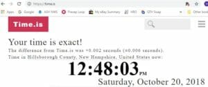
WSJT-X uses your computer’s clock to begin the transmissions at the correct time. If your clock is more than several seconds fast or slow the band activity window and the waterfall will be empty. If you are off by a couple of seconds you may see decoded signals and the waterfall may still be unable to decode weak signals. Type time.is into your browser to see the correct time and your clock’s error. The website time.is will indicate the correct time and your clock’s error as shown in Figure 5. The closer you are to exact the better but anything less than 1 second is probably good enough.
Dimension 4 at http://www.thinkman.com/dimension4/default.htm is a popular app that will automatically keep your computer’s clock set to the correct time. It is an easy download and install.
A second approach is to use the AutoSet included in Windows. The Windows clock auto-set function is set to update every 7 days which is unacceptable. The typical computer clock will drift from the correct time in a few hours or less.
The value stored in register SpecialPollInterval is the number of seconds between updates. It can be changed. I use 3600 decimal which results in hourly updates and is adequate on my heavy desktop workstation. It may not be adequate for a laptop. The register is at HKEY_LOCAL_MACHINE\SYSTEM\CurrentControlSet\Services\W32Time\TimeProviders\NtpClient for those brave enough to use Window’s regedit to make the change. I use this approach for various reasons, time.is returns “Exact” every time I check it.
A third method is generally not recommended but it is effective when you cannot install an app or modify the registry due to permissions. It is also useful if you want to briefly run WSJT-X on a computer without installing Dimension 4.
In Windows, you can right-click on the clock and select “Adjust date/time”. Deselect “Set time Automatically” and then manually set the time a few seconds back or forward. Now reselect “Set time Automatically”. You may need to do this twice. Time.is will eventually report your time as Exact. You will need to check the time every hour and before you start using WSJT-X.
Going Forward
It is easy to set up and use WSJT-X. I have only touched on a few basics aimed at the first time user. As you gain experience your approach will evolve. Some of the guidance I have included here is meant to help the new user start logging QSOs quickly without causing problems. Once you have more experience you will develop your own strategy and will want to move beyond the basics outlined above. The “etiquette” rules related to drive levels and RF output power will continue to apply.
One last word on operating. While WSJT-X is automated it is not “set and forget”. It is nice when you click “Tx Enable” or click a CQ call and it automatically starts sending CQ at the appropriate time and automatically steps through the QSO as shown in Figure 6 and the following text:
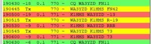
I double clicked WA3YZD who was calling CQ. — green (CQs)
FT-8 sent his call, my call, and Grid Square — yellow (I sent)
WA3YZD’s FT-8 responded with an SNR — red (his response)
(these are the default colors, they can be changed)
As seen in Figure-6 the process continued through FT-8 sending his SNR, he sent a roger roger roger, and we closed with 73 at which point the WSJT-X log popped up and I clicked save. Another one in the log. (until you download and install JTALERT you can import the WSJT-X log file in .adi format into your logging program)
It would be nice if it was always this easy, but it isn’t. Due to propagation (e.g. QSB), operator issues on the other end, and other issues the process can and will go off the rails at any step fairly often. It might get stuck sending “RRR” or “73” every 15 seconds until you intervene and stop it, or it times out. Personally, I feel it is bad form to have it time out because I wasn’t paying attention, more QRM on the band isn’t beneficial.
You have to keep an eye on it every few minutes.
PART-2 “Why WSJT-X / FT-8 / WSPR”
I didn’t see any “sport” in digital modes that are highly automated and do not permit any personal content to be exchanged. I saw it as a small step removed from making contacts over the internet. That is until I downloaded WSJT-X and had my first QSO. I’m a convert.
I found there is a lot of strategy (“sport”) involved and the data available is invaluable for characterizing antennas and propagation which are my two primary interests.
The Band Activity just taken from the WSJT-X FT-8 is shown in Figure-7. The antenna is a 20m RadioWavz dipole ($36 at HRO) hung vertically from a branch at 72’ (22m). This arrangement has a fairly low take-off angle and is good for DX, and useless for anything nearer to NH than OH or FL.
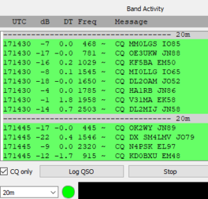
9 of the 12 contacts listed are DX. This is typical for this antenna morning, noon and night. It isn’t unusual for it to show all DX stations. With a little strategy and patience, nearly all of the stations can be worked. Often the DX call signs are unfamiliar to me. Looking up Calls on PathFinder/QRZ keeps me busy. A new ARRL award for getting a WAS or DXCC in the shortest time may be in order.
My 40m full wave Delta loop is good for DX and has a great match on 20m. 4NEC2 modeling shows it to have a high take-off angle on 20m making it a good NVIS antenna. When I select this antenna and wait 30 seconds for a couple of WSJT-X FT-8 updates the list of call signs instantly becomes mostly Northeast US call signs with few or no DX stations. I see a lot of NJ, NY, and PA and an occasional DL or VE3. Once I flip back to the 20m vertical it is once again mostly DX. The data is anecdotal, while it gives me a feel for the antenna’s performance I still do not know the full extent of the antennas pattern. WSJT-X provides several tools for a more analytical look at the antennas performance.
The first tool is PSKReporter. Every spot by FT-8 that has a grid square, which is most, are collected for display. https://pskreporter.info/pskmap.html
Figure-8 is a map of the stations that heard my station on the 20m vertical (yellow) and 40m Delta Loop (blue) over a 24 hour period.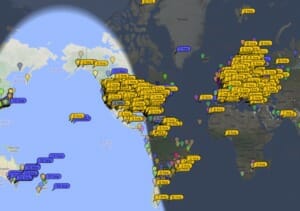 Figure-8 PSKReporter Map
The downloadable tabular data has the SNR at the receiving site.
PSK Reporter collects 500k to 600k reports per hour at its peak from an average of 3000 monitor stations. As can be seen on the map a 24-hour collection provides sparse data in some areas where antenna coverage would be expected. A year ago I tried this same approach using RBN (Reverse Beacon Network) using CW. With fewer than 200 monitors mostly clustered in the US and Europe, the data was even sparser than FT-8 and not very useful for mapping an antennas pattern.
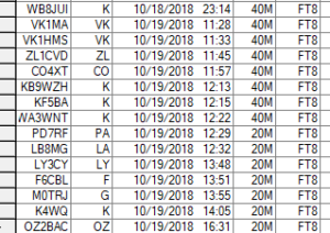
From the PSKReporter data, it was clear that if I wanted Australia and New Zealand I had to use the Delta Loop on 40m and 1100 to 1200 UTC was the best time. Figure-9 is a snip out of my log showing two VKs and a VL right on time. It also shows 9 DXCC entities, 6 of them new to me, not bad for a few minutes OTA over a 3 hours period.
The following day I used the data and logged a JA and JL (Japan) on FT-8 with 25 watts and VS6DJD in So Africa on 20m SSB phone with 1.2kW with solid 59s both ways. Every day I see an Antartica station, that is tomorrow target…..
For Figure-10 I zoomed into the map at my QTH. The broadsides of the Delta Loop are facing 70 degrees and 250 degrees.
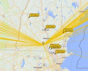
The lines to the NW are to “close in” stations. Those nearer to the 250 heading are to NM, AZ, and CA. The antenna appears to have better directivity than predicted by 4NEC2. It isn’t clear if the directivity is real or if there are simply more monitoring stations at the 70/250 degree headings. The answer to this question is WSPR.
WSJT-X / WSPR
WSPR (pronounced Whisper) is also part of the WSJT-X download. Once you have FT-8 working WSPR will be available. WSPR was designed to evaluate propagation and station performance and does not support 2 way QSOs. Basically, you transmit and monitoring stations provide a signal strength report via the internet. You are also a monitor reporting the signals you hear at your QTH. The reports can be seen at wsprnet.org. WSPR collects about 47k reports per hour and over 1M reports per day.
The WSPR waveform has a noise floor around -31 dB making it an astounding 10 times more sensitive than FT-8. The transmit period is longer at 2 minutes (FT-8 is 15 seconds), less data is sent, and it is one way further reducing the amount of data sent. The WSPR message is call sign, grid square, and transmit power in dBm.
The maximum and most common transmit power is +37dBm (5 watts) with many stations transmitting 1mW to 1 watt.
WSPR is strictly a low power mode.
WSPR can be scheduled to cover multiple bands and the percentage of time it transmits. It is common to set this from 10% to 20% or 25% percent. At 10% you will transmit 2 minutes in each band scheduled every 20 minutes. The scheduler allows you to select day, night, gray line +/- a time, and other options for each band including receive only.
FT-8 collects data on your station when you and others are actively on the air. The number of available transmitters and monitors peaks and dips with global work and sleep schedules.
Many WSPR stations are OTA 24/7 and cover multiple bands. Note that as a US Amateur a transmitting station must have a control operator present unless it is a recognized beacon, and WSPR is not classified as a beacon. I find it easy to have my WSPR station on the air 24 hours most days since I work from home. I select “receive only” when I leave my QTH.
A large number of persistent monitoring stations, high sensitivity, and known transmit power makes WSPR superior to FT-8 for characterizing antennas and propagation.
A map of your coverage area can be seen at wsprnet.org. You can also download .csv files by month since the beginning of WSPR in 2008. The 1M line limitation in Excel will only let you see the first day of the month using Excel. Each monthly file is about 30M lines and 375MB. Three month of data is over 1GB.
To mine data on your station, you can use Command prompt tools, MS Access, or my favorite MATLAB. MATLAB has scripts to parse very large files quickly and produce 3D plots and video animations of the data. I have written scripts that produce animated videos showing SNR contours on a map. This shows the Delta Loop has good directivity (>12dB) on 40m but on 20m it isn’t nearly as pronounced as suggest by FT-8 and PSKReporter.
In conclusion, WSJT-X has provided me with a tool I can use to quickly quantify small changes in my station’s performance as I make changes to it with WSPR having the largest impact. I have been able to see minor changes in grounding, DC power filtering, and antenna height and I have just started.
WSJT-X was developed to support scientific research by two Professors; one is a Nobel prize winner. I believe it is an asset to Amateur Radio. With such a large number of users packed into 3 kHz of the spectrum, the rag-chewers have more free space.
Hamilton, K1HMS
Great article!
Thanks for the insight. It is eyeopening!
Hamilton, terrific analysis. Devoid of jargon, clearly and patiently explained, and no assumption of reader’s level of technical knowledge, i.e., I can use this language this way because we both know all about this. Given the range of knowledge, interests and experiences in the membership, this relaxed explanation of this mode is great. Thanks.
Thank you Hamilton.
I too just started with digital modes. Unfortunately, I have had a very difficult time with it. It seems my beloved FT-891 is not easy to configure. After three days of fiddling with Serial Port settings, I finally have rig control… except for PTT.
The audio portion was the simple part – solder up a Din6 plug for the data port on the rig to a pair of audio TRS plugs for the mic/speaker on the USB Sound card.
Without the ability to trigger a PTT from WSJT-X (Or FLDigi), I am shelving my “digital mode” adventure, and I’m going back to CW.
The PTT on Yaesu rigs are the easiest to set up. With the drivers properly installed when you look in the Windows device manager you will see two VCP COM ports. One labeled Enhanced, and the other Standard.
Enhanced is used for CAT/rig control.
Make sure Standard is set to Hardware control before leaving device manager or its RTS and DTR will not toggle. Also note the COM number.
Standard is for PTT by toggling RTS. They don’t even use the RX/TX lines so baud rate, bits, and stop bits are not used on the radio for this 2nd COM port. They “burn” a whole COM port for 1 control line… just for PPT. Of the big three only Yaesu does it this way.
In WSJT/File/Settings/Radio select RST for PTT and the COM port number for the Standard port. This COM port will be different than used in the left setup column for CAT. Do not try CAT for PTT, it won’t work, and VOX is a pain to use.
Set “data PTT” on the radio to RTS.
This applies to the FT-991 as well.
Good luck
Indeed, the CAT control on the FT-891 is relatively simple. As I expected, I could not simply shelve it and let it “win.'”
The trouble I was experiencing all along was the audio connection. As Hamilton correctly mentions, the Yaesu are some of the simplest becuase they run CAT over a USB com port… ubt the FT-891 does not have an internal sound card… so that requires a middle-man device to convey audio signals from the Rig to the computer, and also from the Computer back to the rig.
Signa-Link, TigerTronics… these are the typical “devices” that hams turn to. But in the case of the FT-891, since CAT is run using the RTS over the USB line, “all” you need is to feed it audio.
My problem was me.
I had soldered my Yaesu CT-39 data cable incorrectly to a pair of TRS (3.5 mm audio plugs.) I had mirrored the DATAOUT pin. If you look in the manual, Yaesu shows the female jack on the rig. But I was soldering away, happily checking continuity on the male pins of the cable.
So… I finally have good audio signal into and out of FLDigi.
Now all I need to do is learn how to run a digital operation.
Thanks again.
Hamilton,
Great article! I’ve been using FT8 shortly after it went live a year or so ago. K1JT and company have since developed a version “taylored” for DXpeditions. Commonly referred to as Fox and Hound, the DX station is the Fox while everyone else is the hound. The Fox transmit in consecutive slots below 600 Hz, up to five slots simultaneously. Hounds transmit from 1000 to 4000 Hz, depending on filters used. (An AM filter is good for 6000 Hz.)
Fox/Hound operation allows the RX goal post to sit over the DX station while the Hound’s TX goal post is positioned by you. The Fox will answer a station with a signal report; the Hound’s TX automatically shifts to one of the Fox’s slots to answer with a report. The Fox sends your call and “RR73” and appends the next station in his list. Depending on how many slots the Fox uses, you will see several QSOs at once being decoded from the Fox.
The Hound will transmit for several minutes until he times out if not answered by the Fox. A neat feature of this mode is that only the Fox slots are decoded while the Hound is calling; i.e., there are no decodes of the stations calling the Fox. When the Hound times out or disables transmit, then the calling stations are decoded. This allows the Hound to find a clear slot if he has been inadvertently fighting it out with another station.
One last point: the more slots the Fox uses, the less power in his signal. However, most DXpeditions use amplifiers. That said, today’s rigs at 100W or 200W and good antennas at the DX site are more than adequate to support 3 to 5 TX slots and still produce an easily decoded signal on your end.
73 de TE