Our club has quite a few members who are interested in space communications. We decided to build a simple portable satellite station last year for our 2016 Field Day operation to learn about satellite communications and to create something new for folks to work with during 2016 Field Day.

Our 1.0 Portable Satellite Station was a relatively simple setup built around an HT, an Elk 2m/70cm satellite antenna, and some gear to improve the receive performance and transmit power output of the HT. All of the gear was mounted on a board to make it easy to transport and it is powered by a LIPO rechargeable battery. The gear in our 1.0 station is made up of the following:
- A Kenwood TH-72A Full Duplex 2m/70cm HT
- A Heil headset with a boom microphone to make using the HT easier
- A pair of 2m and 70cm Low-Noise RF switched preamps from Advanced Receiver Research
- A Mirage BD-35 2m/70cm amplifier (this amp produces about 25 – 35W out when driven by the HT)
- A Diamond SX-400 Watt Meter and an MFJ Dummy Load for testing and monitoring
- A RigRunner DC distribution block with voltage and current monitoring and a 4S4P A123 LIPO Battery Pack
- An Elk 2M/440L5 Dual-Band Log-periodic Antenna

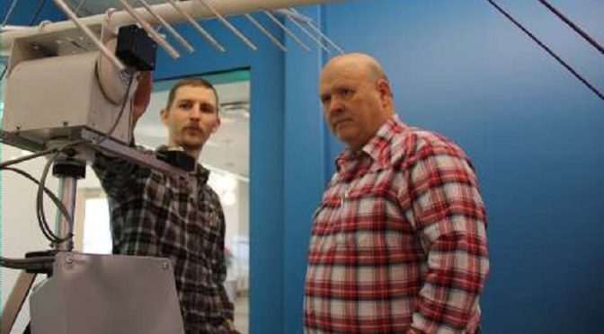
Our first contacts with our 1.0 station were made using the Elk Antenna hand-held. Later, we created a “plumber’s special” setup with a camera tripod to make pointing the antenna easier. Note the angle meter from a local hardware store which measures the elevation angle of the antenna.
 U/V Mode FM Cube Satellite")
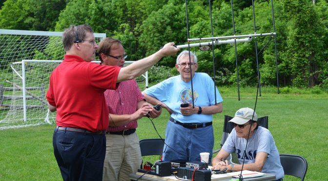
This setup worked great for making FM contacts through AO-85 (Fox-1A), a U/V mode FM EasySat. We used the 1.0 station on multiple occasions including Field Day 2016 and several of our club members used it to make their first satellite contacts. The Full-Duplex HT allowed us to hear our own signal coming back from the satellite which was an important tool to help with aiming the antenna properly. The ELK Dual-Band antenna is also a good choice because it uses a single feed point and a single polarization for both the 2m and 70cm bands.

We used the team operating approach outlined above. This worked especially well for new folks who had not made a satellite contact before as it enabled each of the three team members involved in making the contact to focus on a specific part of the contact. We used orange plastic tent stakes to make AOS, Time of Closest Approach, and EOS to mark headings for each satellite pass. Small flashlights used at the stakes made them glow for night-time passes.
We certainly had a lot of fun with our 1.0 Satellite Station and I expect that we’ll continue to use it. As we gained a little experience with AO-85, we decided that we wanted to build a more capable Portable Satellite Station which we could use to operate with linear transponder satellites and which included a tracking system and better antennas. I know from experience with our home satellite station that DX contacts are possible using higher altitude linear transponder satellites like FO-29.
We would also like to be able to use APRS and other digital modes through satellites as well as receive SSTV pictures from space.
These goals have become the basis for building our Portable Satellite Station 2.0. More on the new station in Part 2 of this series. Other articles in the series include:
- A Portable Satellite Station Part 2 – 2.0 Station Goals and Antenna System
- A Portable Satellite Station Part 3 – 2.0 Station Radio and Supporting Equipment
- A Portable Satellite Station Part 4 – 2.0 Station First Contacts!
You may also be interested in the satellite station at our home QTH. You can read more about that here.
73,
Fred (AB1OC)