Tag Archives: Tower

Fall Antenna Projects at AB1OC/AB1QB

Anita and I like to take advantage of the mild fall weather to do antenna projects at our QTH. We have completed two such projects this fall – the installation of a Two-Element Phased Receive System and a rebuild of the control cable interconnect system at the base of our tower.

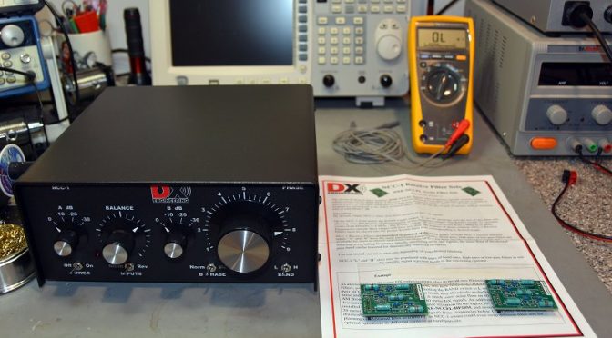
Receive Antenna System Electronics
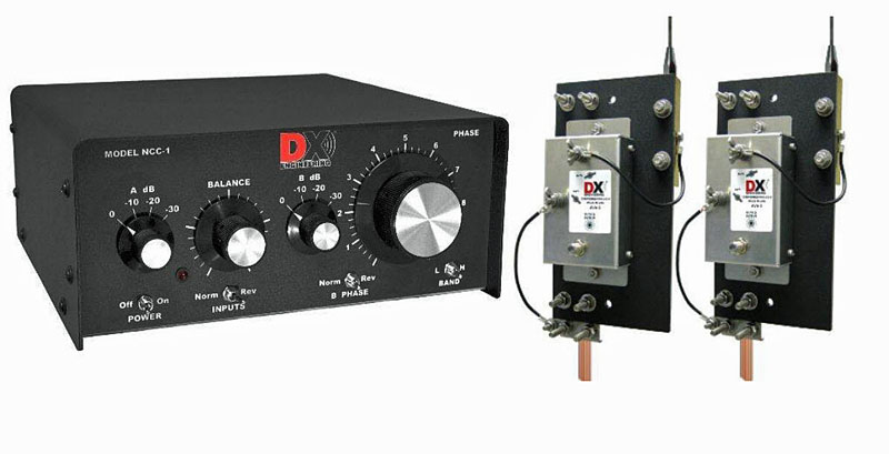
Antenna Projects - NCC-1 Receive Antenna System Components
NCC-1 Receive Antenna System Components

Our first project was the installation of a DXEngineering NCC-1 Receive Antenna System. This system uses two receive-only active vertical antennas to create a steerable receive antenna system. The combination can work on any band from 160m up to 10m. We set ours up for operation on the 80m and 160m bands.
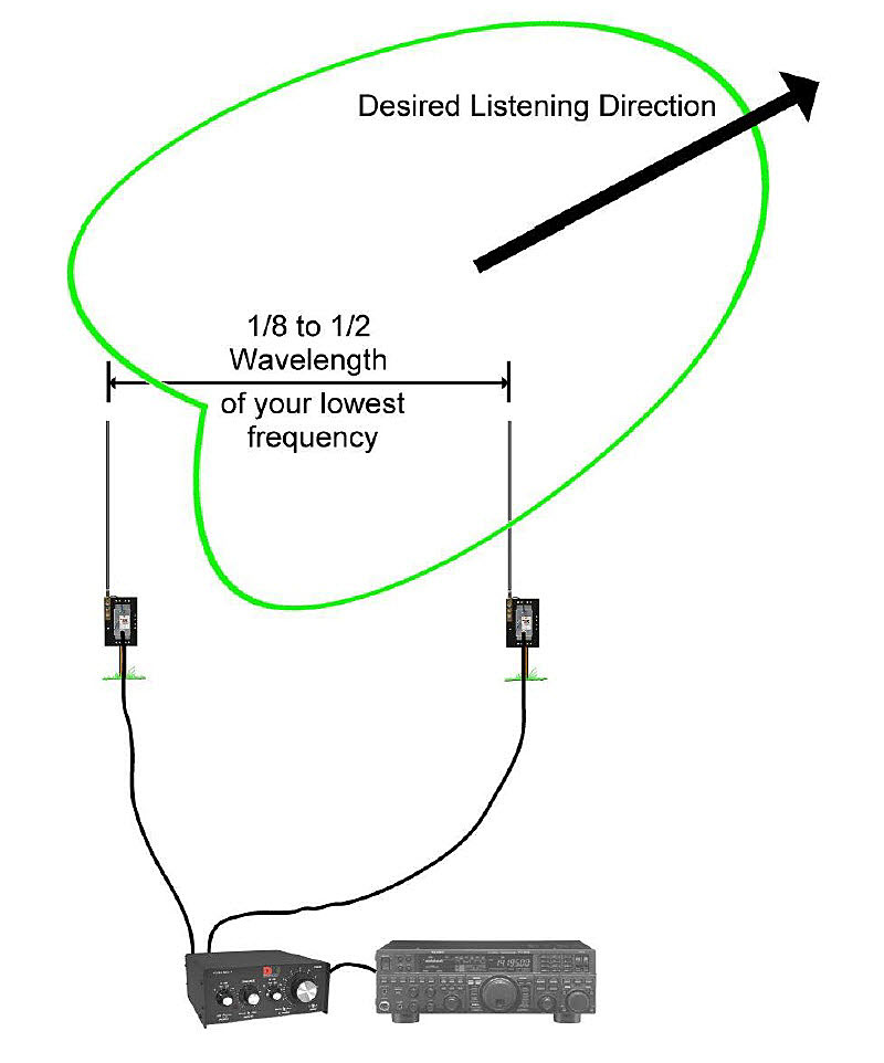
Antenna Projects - NCC-1 Receive System Antenna Pattern
NCC-1 Receive System Antenna Pattern

The NCC-1 System can be used to peak or null a specific incoming signal. It can also be applied to a noise source to null it out. The direction that it peaks or nulls in is determined by changing the phase relationship between the two Active Antenna Elements via the NCC-1 Controller.
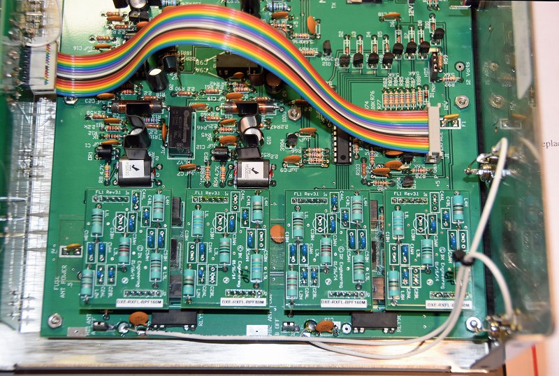
Antenna Project - NCC-1 Filter Installation
NCC-1 Filter Installation

The first step in the project was to open the NCC-1 Control Unit to install a set of 80m and 160m bandpass filter boards. These filters prevent strong out-of-band signals (such as local AM radio stations) from overloading the NCC-1. The internal switches were also set to configure the NCC-1 to provide power from an external source to the receive antenna elements through the connecting coax cables.

Receive Antenna Elements and Coax

 

Antenna Projects - Installed Active Receive Element
Installed Active Receive Antenna Element

The next step in the project was to select a suitable location for installing the Receive Antenna Elements. We choose a spot on a ridge which allowed the two Antenna Elements to be separated by 135 ft (for operation on 160m/80m) and which provided a favorable orientation toward both Europe and Japan. The antenna elements use active circuitry to provide uniform phase performance between each element’s 8 1/2 foot whip antenna and the rest of the system. The antenna elements should be separated by a 1/2 wavelength or more on the lowest band of operation from any towers or transmit antennas to enable the best possible noise rejection performance.
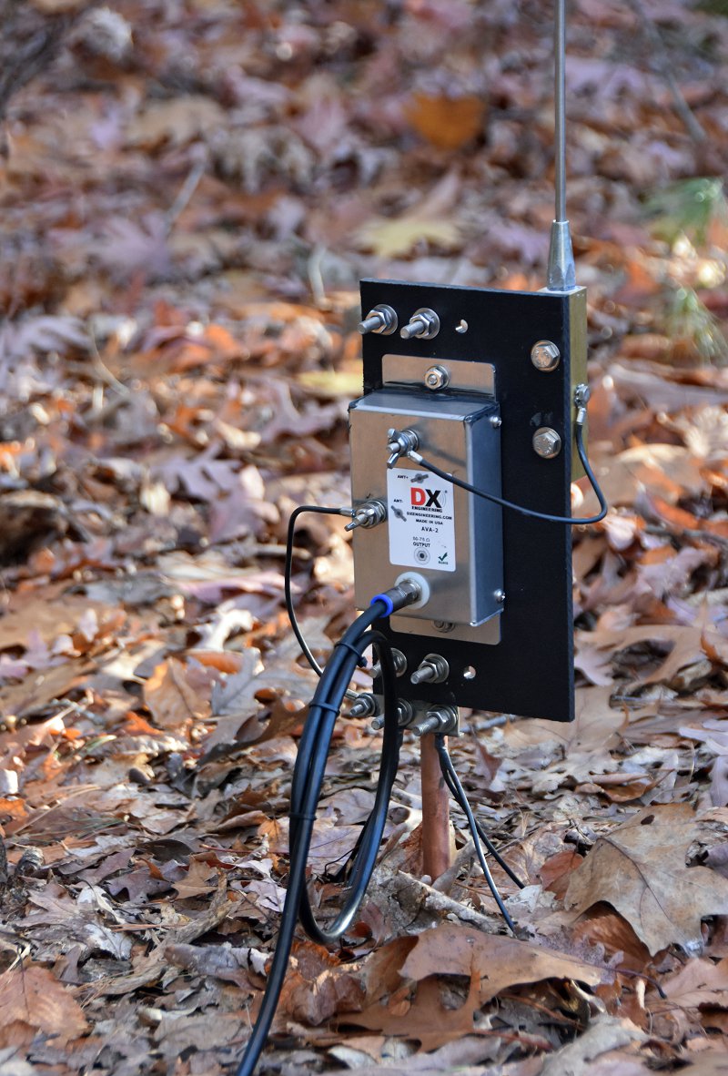
Antenna Project - Received Antenna Element Closeup
Received Antenna Element Closeup

The two Antenna Elements were assembled and installed on 5 ft rods which were driven into the ground. To ensure a good ground for the elements and to improve their sensitivity, we opted to install 4 radials on each antenna (the black wires coming from the bottom of the unit in the picture above). The Antenna Elements are powered through 75-ohm flooded coax cables which connect them to the NCC-1 Control Unit in our shack. The coax cable connections in our setup are quite long –  the length of the pair being approximately 500 ft. The use of flooded coax cable allows the cables to be run underground or buried. Should the outer jacket become nicked, the flooding glue inside the cable will seal the damage and keep water out of the cable.
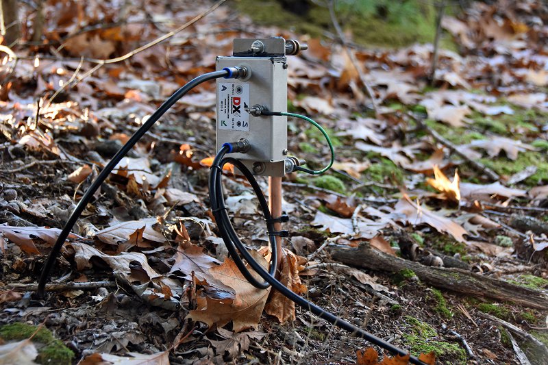
Antenna Project - RFC-1 Receive Line Choke
Receive RF Choke

It is also important to isolate the connecting coax cables from picking up strong signals from nearby AM Radio stations, etc. To help with this, we installed Receive RF Chokes in each of the two coax cables which connect the Antenna Elements to the NCC-1. These chokes need to be installed on ground rods near the Antenna Elements for best performance.
Antenna Project - Underground Feedline Conduit
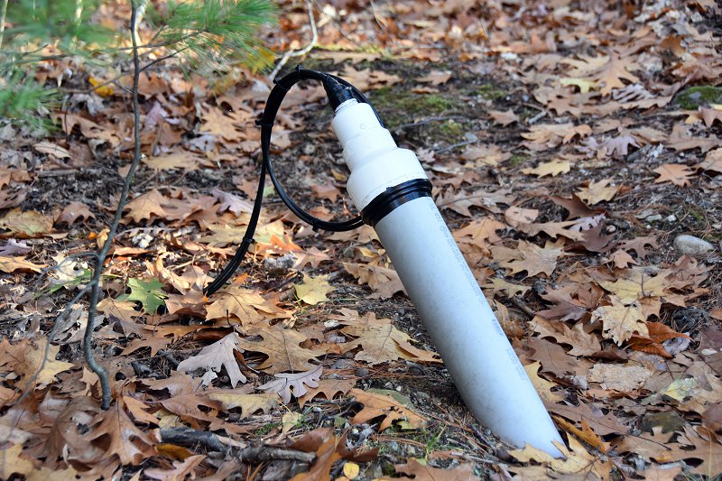
Underground Cable Conduit In Our Yard

We ran the coax cables underground inside cable conduits for a good portion of the run between the antenna elements and our shack. The conduits were installed in our yard when we built our tower a few years back so getting the coax cables to our shack was relatively easy.
Antenna Project - Receive Antenna Coax Ground System
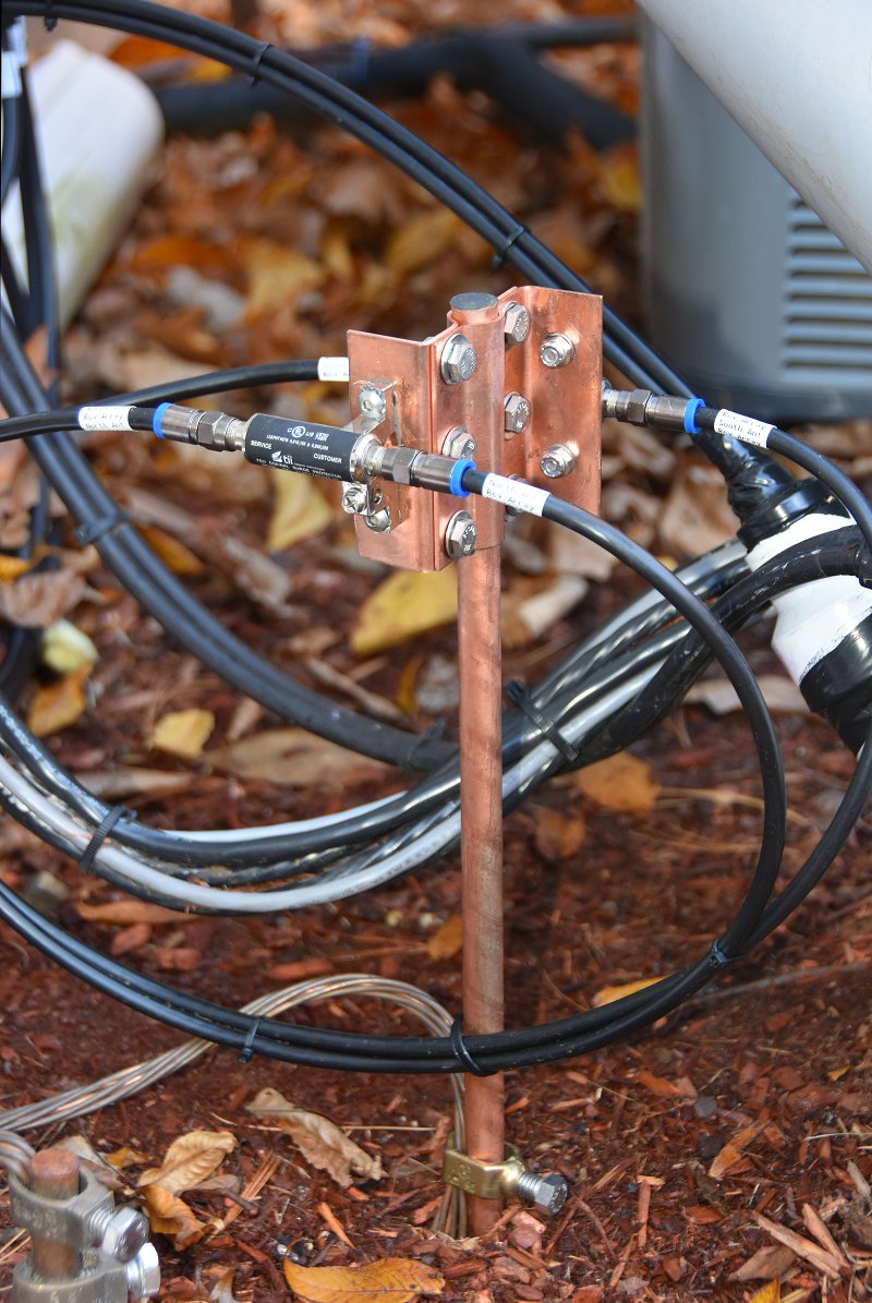
Receive Antenna Coax Ground System

The last step in the outdoor part of this project was to install a pair of 75-ohm coax surge protectors near the entry to our shack. An additional ground rod was driven for this purpose and was bonded to the rest of our station’s ground system. We routed both of the 75-ohm coax cables from the two Antenna Elements through surge protectors and into our shack. Alpha-Delta makes the copper ground rod bracket shown in the picture for mounting the surge protectors on the ground rod.

Shack Installation
 

Antenna Project - Equipment Shelf In Our Shack
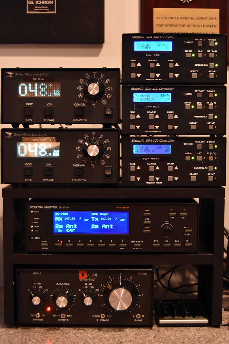
Antenna Equipment Shelf In Our Shack (The NCC-1 Control Unit Is At The Bottom)

The installation work in our shack began with the construction of a larger shelf to hold all of our antenna control equipment and to make space for the NCC-1. The two incoming coax cables from the Antenna Elements were connected to the NCC-1.
Antenna Project - uHAM Station Master Deluxe Controller
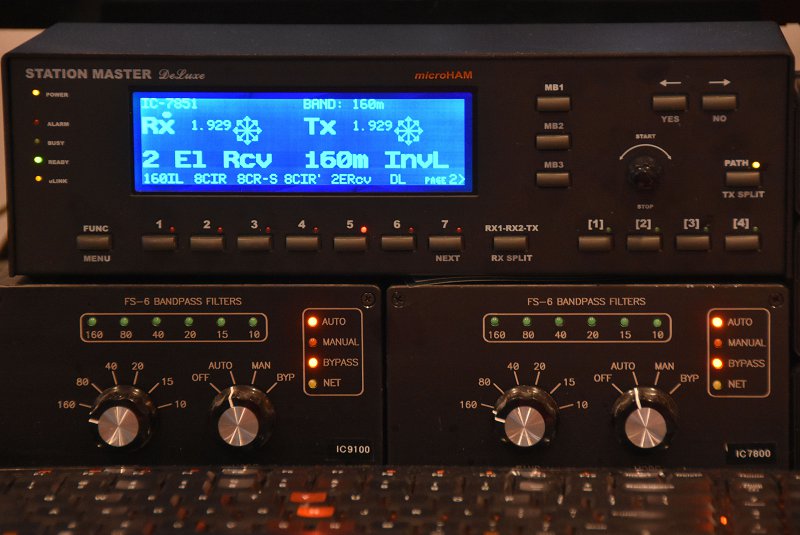
microHAM Station Master Deluxe Antenna Controller

Antenna switching and control in our station is handled by a microHAM System. Each radio has a dedicated microHAM Station Master Deluxe Antenna Controller which can be used to select separate transmit and receive antenna for the associated radio. The microHAM system allows our new Receive Antenna System to be shared between the 5 radios in our station.
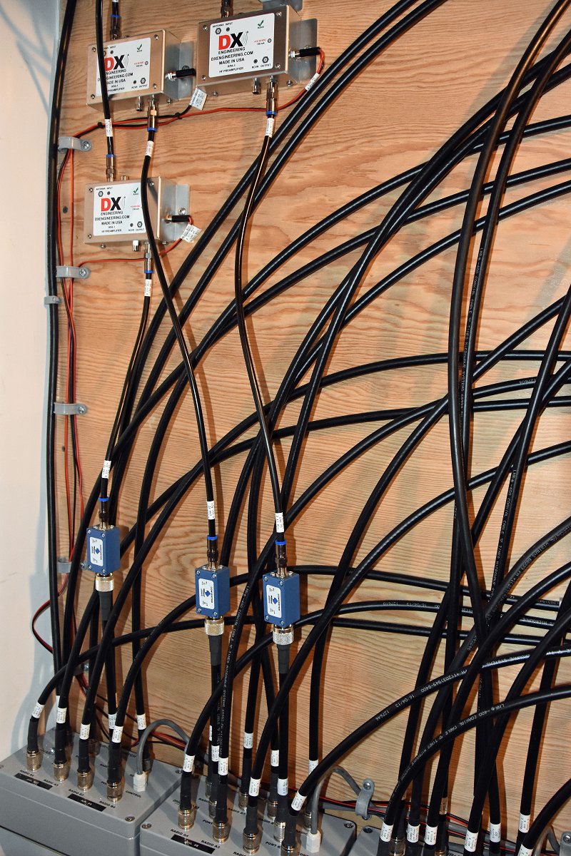
Antenna Project - Switching Matrix
Antenna Switching Matrix

The first step in integrating the Receive Antenna System was to connect the output of the NCC-1 to the Antenna Switching Matrix outside our shack. We added a low-noise preamp (shown in the upper left of the picture above) to increase the sensitivity of the Antenna System. The blue device in the picture is a 75 ohm to 50-ohm matching transformer which matches the NCC-1’s 75-ohm output to our 50-ohm radios. The other two preamps and transformers in the picture are part of our previously installed 8-Circle Receive Antenna System.

Protection From Overload
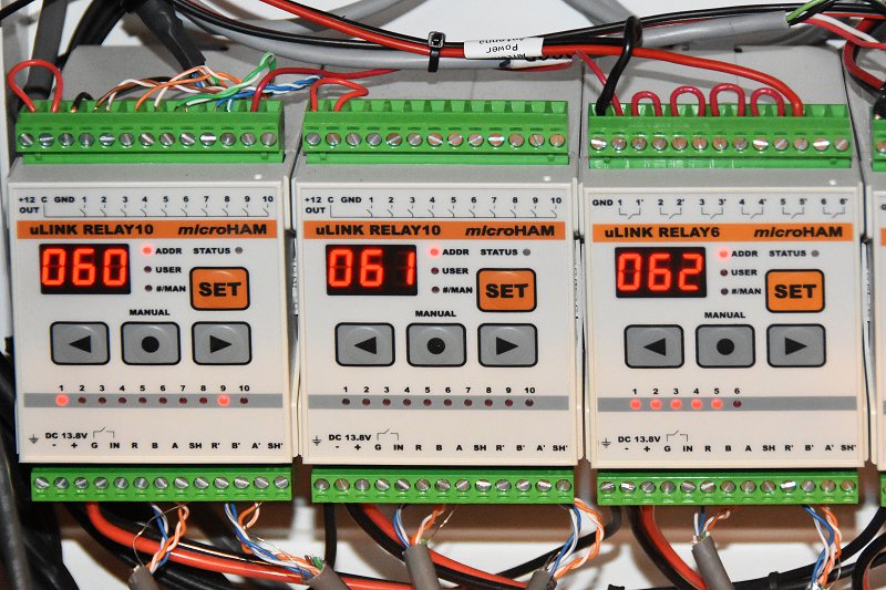
 

Antenna Project - Multi-Radio Sequencer
Multi-Radio Sequencer

The Antenna Elements must be protected from overload and damage from strong nearly RF fields from our transmit antennas. In a single radio station, this can be handled via a simple sequencer unit associated with one’s radio. In a multi-op station such as ours, it is possible for a different radio than the one which is using the Receive Antenna System to be transmitting on a band which would damage the Receive Antenna System.

To solve this problem, we built a multi-radio sequencer using one of the microHAM control boxes in our station. The 062 Relay Unit shown above has one relay associated with each of the five radios in our station. The power to the Receive Antenna System is routed through all 5 of these relays. When any radio transmits on a band that could damage the Antenna Elements, the associated relay is automatically opened 25 mS before the radio is allowed to key up. This ensures that the system’s Antenna Elements are safely powered down and grounded.

On The Air Performance
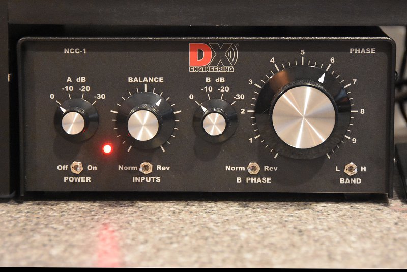
Antenna Project - NCC-1 Controls
NCC-1 Controls

So how well does the system work? To test it, we adjusted the NCC-1 to peak and then null a weak CW signal on 80m. This is done by first adjusting the Balance and Attenuator controls on the NCC-1 so that the incoming signal is heard at the same level by both Antenna Elements. Next, the B Phase switch is set to Rev to cause the system to operate in a signal null’ing configuration and the Phase control is adjusted to maximize the null’ing effect on the target signal. One can go back and forth a few times between the Balance and Phase controls to get the best possible null. Finally, the incoming signal is peaked by setting the B Phase switch to Norm.
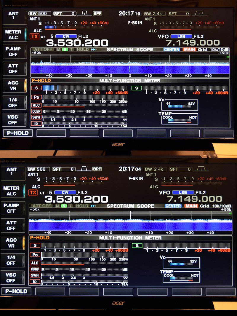
Antenna Project - Peaked And Nulled CW Signal
Peaked And Null’ed CW Signal

The picture above shows the display of the target CW signal on the radio using the NCC-1 Antenna System. If you look closely at the lower display in the figure (null’ed signal) you can still see the faint CW trace on the pan adapter. The difference between the peak and the null is about 3 S-units or 18 dB.
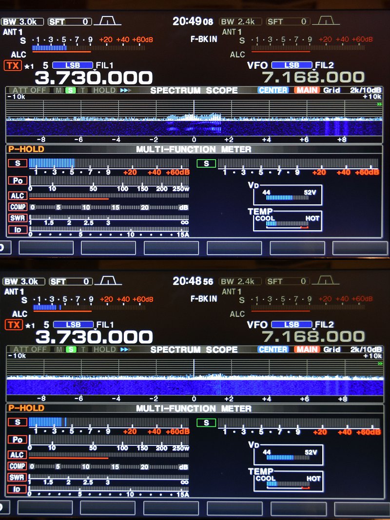
Antenna Project - Peaked And Nulled SSB Signal With NCC-1 Used For Noise Cancellation
NCC-1 Used For Noise Cancellation

The NCC-1 can also be used to reduce (null out) background noise. The picture above shows the result of doing this for an incoming SSB signal on 75m. The system display at the top shows an S5 SSB signal in the presence of S4 – S5 noise. Also, note how clean the noise floor for the received SSB signal becomes when the unit is set to null the noise source from a different direction than the received SSB signal.

We are very pleased with the performance of our new Receive Antenna System. It should make a great tool for DX’ing on the low-bands. It is a good complement to our 8-circle steerable receive system which we use for contesting on 160m and 80m.

Other Antenna System Maintenance
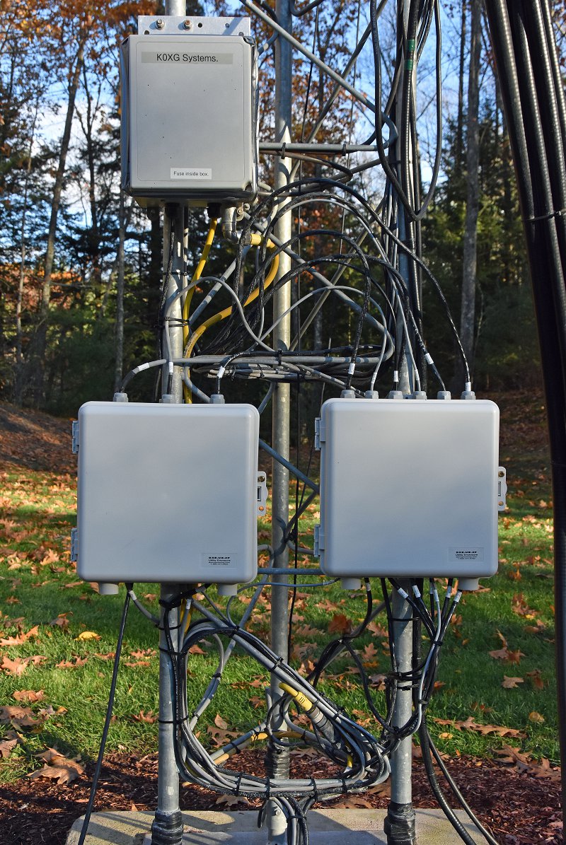
Antenna Project - Tower Control Cable Interconnects
Tower Control Cable Interconnects (Bottom Two Gray Boxes)

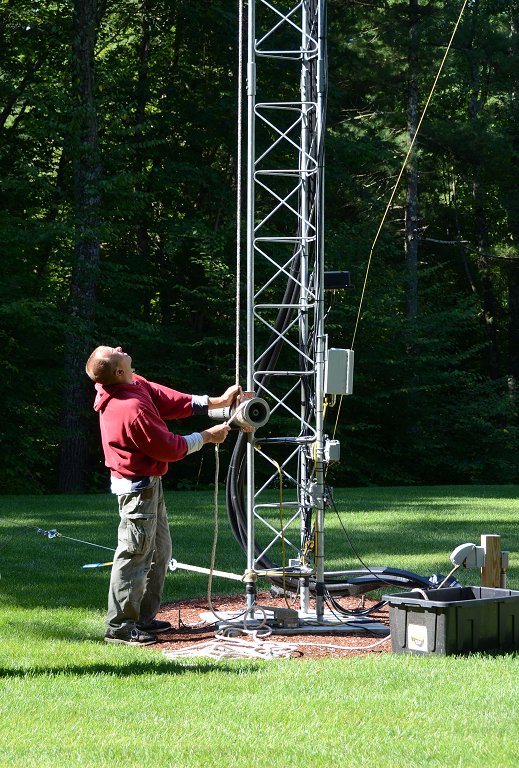
Our other antenna project was a maintenance one. We have quite a number of control leads going to our tower. When we built our station, we placed surge protectors at the base of our tower. We then routed all of our control leads through exposed connections on these units. Over time, we found that surge protection was not necessary. Also, we became concerned about the effects that sunlight and weather were having on the exposed connections. To clean all of this up, we installed two DXEngineering Interconnect Enclosures on our tower and moved all the control cable connections inside them.
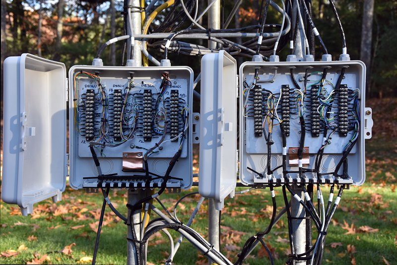
Antenna Project - Inside View Of Interconnect Enclosures
Inside View Of Interconnect Enclosures

We began with a pair of enclosures from DXEngineering and we mounted screw terminal barrier strips on the aluminum mounting plates in each enclosure. The aluminum plates are grounded via copper strap material to our tower.
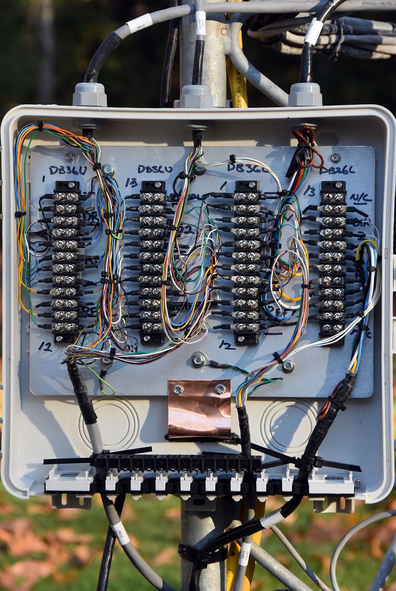
Antenna Project - Closer Look At The Interconnects
Closer Look At One Of The Interconnect Enclosures

The picture above shows one of the interconnection boxes. This one is used to connect our two SteppIR DB36 Yagi Antennas and some of the supporting equipment. The barrier strips form a convenient set of test points for troubleshooting any problems with our equipment on the tower. There are almost 100 control leads passing through the two enclosures. This arrangement keeps everything organized and protected from the weather.

With all of our antenna projects complete, we are looking forward to a fun winter of contesting and low-band DX’ing.

Fred, AB1OC

The Nashua Area Radio Club is Number 1 Field Day Again!

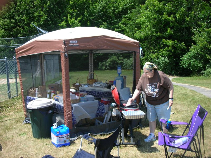
We got up to some great news this morning. The Nashua Area Radio Club is once again Number 1 Field Day!!

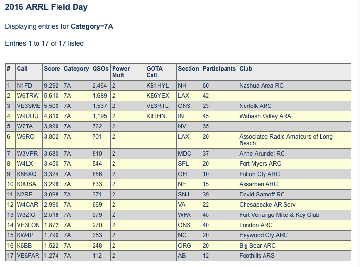
2016 ARRL Field Day Results - 7A Category
2016 Results – 7A Category

We are the Top Club in our Category (7A) for 2016 with a final score of 9,292. The next closest club was W6TRW with a score of 5,610. You can see all the 2016 results on the ARRL score page. For a more detailed breakdown of our score for 2016, check out our Field Day page.

Congratulations to everyone who helped to make our 2016 operation a success! Also, a special thank you to our planning team –

Our 2016 Field Day Planning Team
Our Planning Team
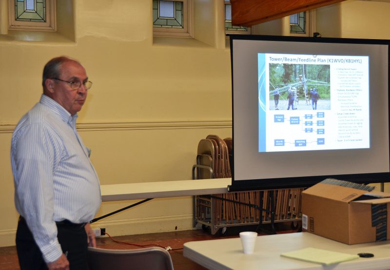
Field Day Presentation
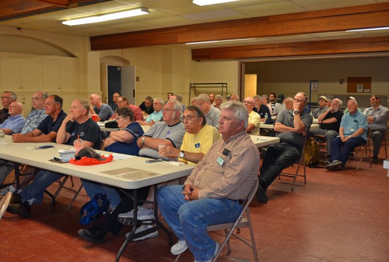
Mike, K1WVO Helping To Deliver Our Field Day Presentation During Our Club Meeting
Field Day Presentation
Presentation At Our Club Meeting

We certainly have many great memories from our 2016 Operation. I spent some time today looking at the photos from our 2016 Operation and the video from our 2016 Operation again. I picked out some photos to share here –

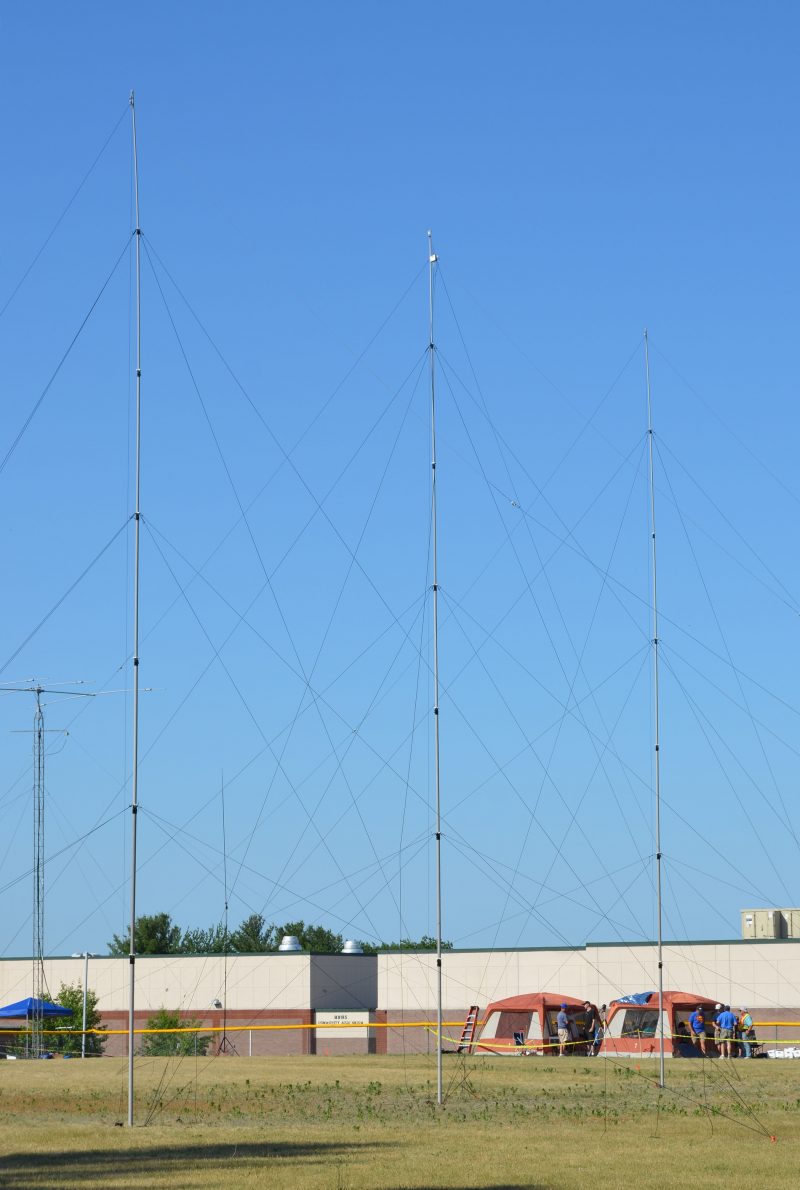
40m V-Beam
Our 40m V-Beam

Our setup was well planned and the execution was top-notch!

CW Row
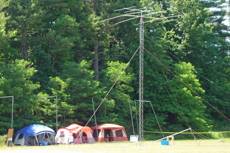
CW/6m Row With One Of Two Of Our Towers And Beams
20m CW Op
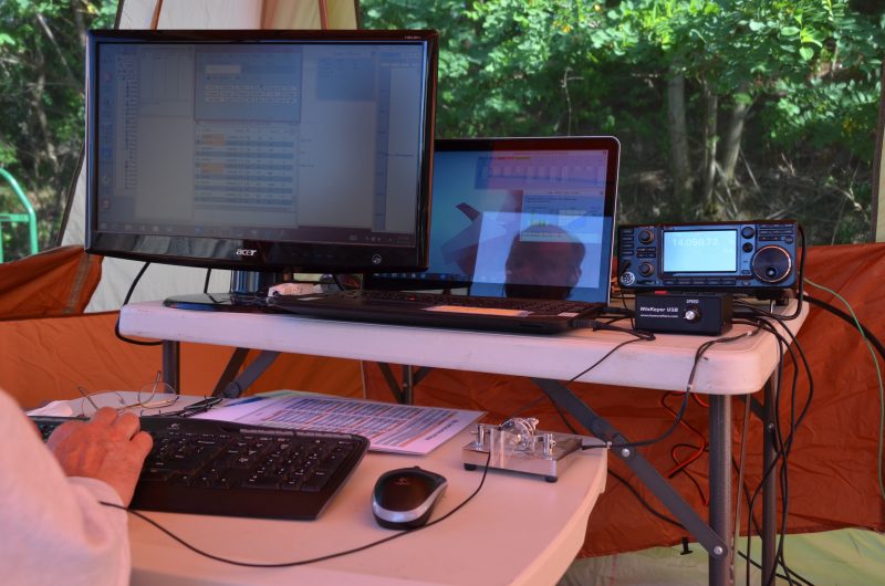
20m CW Station
DATV Station Equipment
SSB Stations and Digital ATV Station on 70 cm
Satellite Station Equipment
LEO Satellite Station

Many folks in our club pulled together to build our setup and we operated hard during Field Day.

Mike, KU1V Operating During Field Day 2016
Mike, KU1V Operating
40m CW Op
Ed, K2TE Operating 40m CW
20m CW Op
Bill, NJ1H Operating 20m CW
20m SSB Op
Jamey, KC1ENX, Operating 20m SSB
75m-15m SSB Op, AB1BY
Abby, KC1FFX Operating on 75m SSB
40m SSB Ops
Brian, AB1ZO Operating on 40m SSB
Jeff, WA1HCO Operating On 6m During Field Day 2016
Jeff, WA1HCO Operating On 6m
Field Day Fun
Field Day Fun 2016
Field Day Feast!
Merle, W1MSI Provided Us With A  Feast!

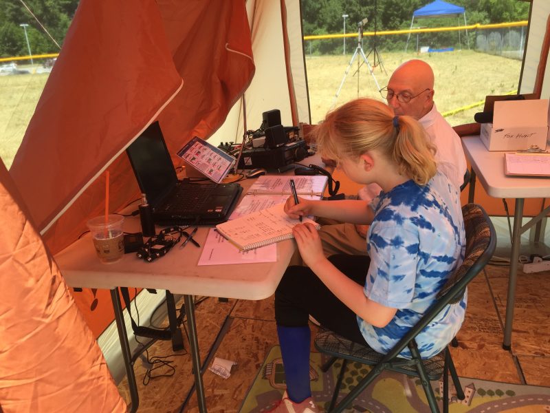
We also helped to introduce folks to Amateur Radio via our GOTA Station.

Field Day GOTA Station
Our GOTA Station Provided By Wayne, KB1HYL

It’s fun to think about all the great things that went on during Field Day this year.

Our 2016 Highlights Video

Looking forward to our 2017 Field Day operation!!!

Fred, AB1OC
Hashtag: #ARRLFD

Summertime Station and Antenna Projects At AB1OC/AB1QB

Summer is the time of year that many of us work on our antennas and improve our stations. Anita AB1QB and I did both of these things at our QTH this summer.

Antenna Projects - Removing Lower SteppIR Yagi From Tower
Removing Lower SteppIR Yagi From Tower

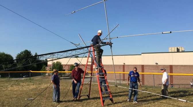
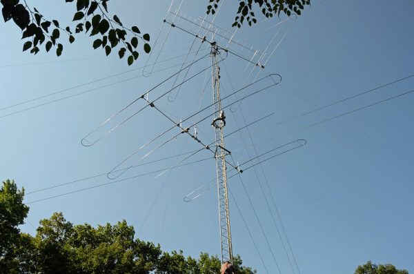
Our SteppIR DB36 Yagis were due for some maintenance so we took them off our tower. Special thanks to all the members of the Nashua Area Radio Club who helped us remove, recondition and reinstall our antennas! Matt Strelow, KC1XX of XX Towers and Andrew Toth provided equipment and know how to safely remove our two large SteppIR DB36 Yagis with help from the rest of us.

Antenna Projects - Lowering Antenna With Electric Winch
Lowering Antenna With Electric Winch

The SteppIR DB36 Yagis weigh almost 200 lbs each and Matt made good use of his electric winch to lower them.

Antenna Projects - Antenna Coming Down The Tram Line
Antenna Coming Down The Tram Line

The picture above shows the lower antenna coming off the tower. We used a Tram Line system to lower both antennas to the ground so that we could rebuild them.

Antenna Projects - SteppIR DB36 Antenna On The Ground
SteppIR DB36 Antenna On The Ground

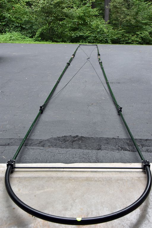
The SteppIR DB36 Yagis are quite large. They have 36 ft booms and the driven elements are almost 50 ft from tip to tip! They completely fill up our back yard when they are both off of the tower.

SteppIR Rebuild

Antenna Projects - Element Pole Sun Damage
Element Pole Sun Damage

The rebuild process began with a careful inspection of both antennas. They were both in good overall condition with some sun damage to the paint on the fiberglass element poles.

Antenna Projects - Disassembled SteppIR DB36
Disassembled SteppIR DB36

We removed all the element tubes and sweeps from both antennas for rebuilding. The picture above shows the disassembled upper antenna.

Antenna Projects - Rebuilt Stepper Motors Installed
Rebuilt Stepper Motors Installed

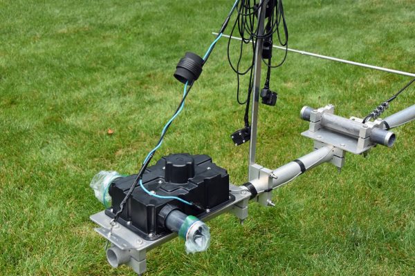
All four Stepper motors on both antennas were replaced. These motors move metal tapes inside hollow element tubes to adjust the length of each antenna’s 4 movable elements. These adjustments are done automatically by controllers in our shack which receive frequency information from the radios which are connected to each antenna.

Antenna Projects - Reconditioned Element Sweep Poles
Reconditioned Element Sweep Poles

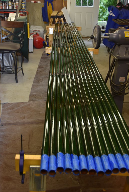
All of the element housing poles were cleaned, prepped and painted with a UV resistant clear coat to protect them from further sun damage. The poles cleaned up like new.

Antenna Projects - New Element Sweeps Ready For Installation
New Element Sweeps Ready For Installation

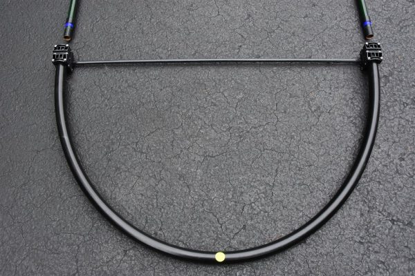
The assembly of all the new element sweep tubes (shown above) was done next. Each antenna has six sweeps.

Antenna Projects - Element Pole Preparation
Element Pole Preparation

The end of each element pole must be prepped with a tape system which ensures that the poles are seated properly, sealed to and firmly attached to the sweeps. This process and the associated assembly and tightening of the element couplers was the most time-consuming step in the rebuilding process as it had to be repeated a total of 24 times.

Antenna Projects - Rebuilt Element Assembly
Rebuilt Element Assembly

Here’s a picture of one of the rebuilt element tube assemblies. The ropes support the element tubes and keep them aligned when the antenna is up in the air. These elements are attached to the antenna motors with couplers and clamps.

Antenna Projects - SteppIR DB36 Yagi Rebuild Complete
SteppIR DB36 Yagi Rebuild Complete

The picture above shows the lower antenna with all the element tubes reattached. There is quite a bit of additional prep work associated with adjusting all the supports and taping all the exposed areas of the antennas which are susceptible to sun damage. Also, all the electrical wiring on the antenna must be checked to ensure good electrical connections and good overall condition of the wiring.

SteppIR Ground Testing


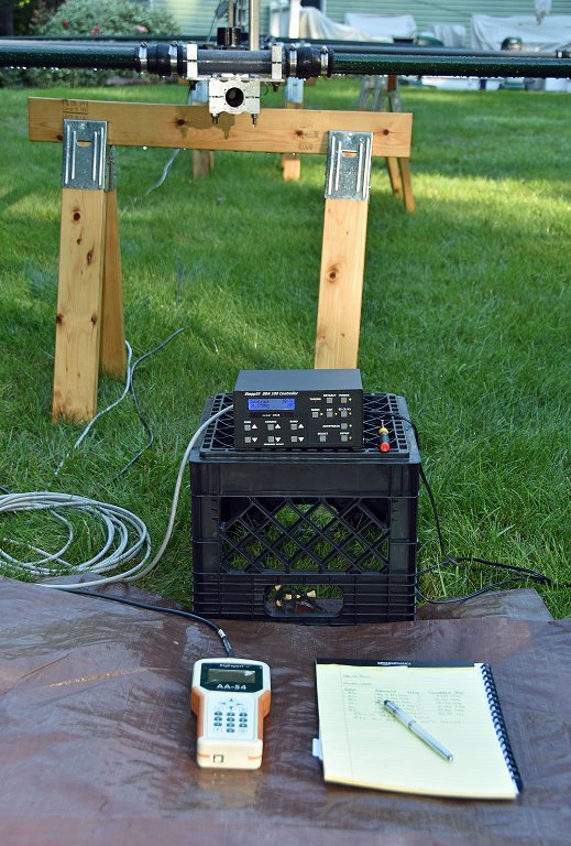
Antenna Projects - Ground Test Setup
Ground Test Setup

The final step in rebuilding the antennas is to test their operation on the ground. This ground test is done to ensure that all the motors are working correctly and that the element tapes move smoothly inside the rebuilt element tubes.

Antenna Projects - Ground Test Results
Ground Test Results

Another important part of the antenna Ground Test is to confirm that the antennas have a consistent resonant frequency and SWR on all bands. The resonant frequencies and SWR levels are far from those that would be measured when the antennas are on the tower at operating height. The idea here is to confirm that a resonance exists and that its frequency and SWR readings are repeatable as the antenna is adjusted to different bands.

SteppIR Installation and Final Testing


Tramming Antennas Onto A 100 Ft Tower

With both antennas rebuilt, its was time for Matt and Andrew to return and, with help from folks from our club, reinstall the rebuilt antennas on our tower. The video above shows this process. It is quite something to see! The installation took about 3 1/2 hours.

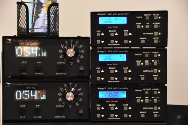
Antenna Projects - Updated SteppIR Controllers
Updated SteppIR Controllers

The last step in the SteppIR DB36 rebuild process was to install the latest firmware in the associated SDA100 Antenna Controllers. There were some integration issues between the updated SteppIR Firmware and our microHAM system but we are getting those worked out with help from the folks at both SteppIR and microHAM.

Transceiver Upgrade


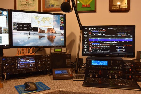
Icom IC-7851 With Display Monitor

I recently had a major birthday milestone and Anita surprised me with a new radio – an Icom IC-7851. This radio is an upgrade/replacement for our Icom IC-7800. While the two radios are quite similar in their operation and interfaces, I did not want to install the IC-7851 until the SteppIR antennas were reinstalled and all of their upgrades were working properly with our current radios. With the antennas done, it was the time to install the new radio!

Icom C-7851 Transceiver

The Icom IC-7851 has several important performance upgrades. The most impactful one is a new low phase noise oscillator which significantly improves RMDR performance compared to the IC-7800. The IC-7851 is in the top-tier of Transceivers in Sherwood Engineering’s tests. The receivers in the IC-7851 are very quiet, have excellent Dynamic Range and perform great in when close-in interference is present.

Icom IC-7851 Display Monitor

The Icom IC-7851 has a higher resolution and faster display. It also supports higher resolution external monitors so we installed an upgraded display monitor along with the new radio. The IC-7851 has a number of new networking features and supports stand-alone remote operation over a LAN and the Internet. We are planning to use these capabilities to add a second remote operating gateway to our station. More on this in a future article.

The combination of the rebuilt antennas and the new IC-7851 Transceiver has our station performing better than ever. The antennas are working as well or better than when they were new and the IC-7851 has significantly better receive performance compared to its predecessor and is a pleasure to use.

We will be hosting the ARRL Rookie Roundup RTTY contest for our club members who have received their first license in the last 3 years next weekend and we’re going to use the new radio and rebuilt antennas for the contest.

This project was completed in a little over two weeks and was a lot of work. I could not have done the project without the help of the many folks in our club. Again, a big Thank You to all the folks in our club who helped me with this project! I hope that many of you will be able to find some time to operate from our upgraded station.

73,

Fred, AB1OC

Radio Amateurs Developing Skills Worldwide