Fortunately, the Nashua Area Radio Club had a Technician License class coming up and we thought that the new station test would be a great way for our students to learn about Amateur Radio Satellites.
Satellite Status from AMSAT Website
Final preparations included checking the operational status of potential satellites on the AMSAT website. The page shown above is like a spotting cluster for LEO Satellites – it shows satellite activity as reported by HAM satellite operators. Using this information, we configured MacDoppler to track the active satellites.
Satellite Pass Predictions
Next, we used MacDoppler to generate pass predicts for the weekend of our Technical Class. We assembled this data for all of the potential satellites and color-coded the available passes to identify those which had the best chance of producing contacts.
With this done, we loaded our portable tower, antennas, and all of the rest of the gear into our pickup truck and transported it to the class site.
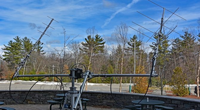
Satellite Antennas Setup Portable
The first step at the class site was to unload all of our gear and move the portable tower to a suitable location. We used a compass to orient the tower to true north and leveled it. We used the weight bags that we made up to anchor the tower securely and then installed the antennas, rotator loops, and control cables. The antenna system worked out very well in the portable environment and was easy to set up.
Satellite Antenna Details
Here’s a closer to look at the LMR-400 UF coax cables which connect the antennas to the rest of the system. The loops just behind the antennas are necessary to keep the coax from affecting the pattern of the antennas. The coax cables shown were made long enough to allow the antennas to be rotated through their full travel in the azimuth and elevation directions without binding.
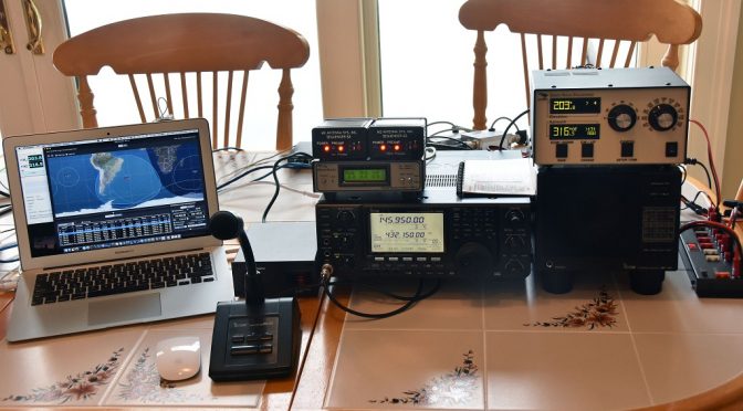
Satellite Station Portable – Radio and Supporting Equipment
The final step in the portable setup was to put the IC-9100 Transceiver and Supporting Equipment together in the building and check everything out. As soon as we got everything hooked up and working, we heard an ON4 station through FO-29 which was near the end of a low angle pass. A very good sign!
We took some time to fine-tune the calibration of our rotators and to check the operation of the computer controls – everything checked out fine. The video above shows MacDoppler controlling the Azimuth/Elevation rotator and the IC-9100 Transceiver during the testing.
First Contact using New 2.0 Station (via AO-85)
With all the setup done, it was time to try to make our first contact. Fortunately, we did not have long to wait. We caught a medium angle pass of AO-85, a U/V Mode FM Easy Sat. With MacDoppler setup and tracking, we immediately heard contacts being made through AO-85. I gave a whistle and adjusted my uplink VFO until I heard my signal coming back through AO-85. I gave a quick CQ call and immediately got a response from Jonathan, NS4L in Virginia, USA! It took on a few seconds to exchange call signs and grid squares and our first contract with our new station was in the log.
Explaining Satellite System to License Class
Our Technician License Class students were very interested in the station. We spent some time explaining the setup and demonstrating how it worked. We made more contacts between our class sessions using AO-85 and FO-29 (a V/U Mode Linear Transponder Satellite). Our most interesting contact was with Burt, FG8OJ in Guadeloupe through FO-29. It was great to work DX using the new station during the first time we used it.
We learned several things during our first use of the new station. First, while the 35 ft. maximum separation allowed between the antenna system and the rest of the station is adequate in many applications, the antenna system’s close proximity to the building we were in blocked passes to the west of us with this separation. We have subsequently made up an additional set of feed lines using a pair of 100 ft. long 7/8″ hardline coax cables to allow for a greater separation in portable deployments such as this one.
We were glad that we had the Heil Pro 7 Headset with us and we used it for most of our contacts. The separate speaker allowed our students to hear the contacts well and the boom microphone on the Pro 7 Headset eliminated feedback due to our own voice coming back through the satellites. We improvised a mono to stereo converter cable to connect the Heil Pro 7 Headset to one of the two speaker outputs on the IC-9100 Transceiver. This allowed the radio to drive the separate speaker and the headphones at the same time.
We were glad to have the low-noise preamps available. These were especially useful during low-angle satellite passes and the sequencing setup that we built worked well.
All in all, our first test of our new 2.0 Portable Satellite station was a success. Our license classes students enjoyed learning about Amateur Satellites and had fun along with us making contacts through a few of them. Our next goal will be to get packet modes and APRS working with our setup. We plan to do another article in this series when this part of our project is completed. Other articles in this series include:
We are planning to add larger antennas and switchable polarity to our portable satellite station in the near future. This will enable us to make contacts with Satellites and the ISS in more difficult conditions.
The Icom IC-9100 provides 100W on 2M and 75W on 70 cm which is more than enough power for our application. It also has some nice satellite features such as support for synchronized VFO tracking between the 2M and 70 cm VFOs on the radio. This radio also uses a single USB connection to allow computer control of the radio and creation of a sound card interface on the host computer. A Heil Proset 7 will be used for operator audio to avoid feedback due to our audio coming back from the satellite. The Icom SP-23 speaker is included to allow observers to hear satellite contacts while they are in progress.
Radio Management via MacDoppler
The MacDoppler software provides automated control of the IC-9100 including mode selection and automatic correction of both VFOs for Doppler shift. These features greatly simplify the operation of the radio, especially when satellites with SSB/CW transponders are used.
The video above shows MacDoppler’s management of the IC-9100 Transceiver during a pass of AO-73. The constant adjustments of the VFOs take care of Doppler shift correction and ensure that our signal stays at a fixed position in the transponder passband of linear transponder satellites.
Preamp Sequencers and Output Monitoring
M2 Antenna Systems S3 Sequencers are used to provide control of the Advanced Receiver Research low-noise preamps on our portable tower. One of the nice features of the Icom IC-9100 is that it can be configured to provide separate keying lines for the 2M and 70cm VFOs. This allows a preamp to remain enabled on the receive VFO while the other VFO is in transmit mode with its preamp shut down by the sequencer. This arrangement is very useful during tuning when one needs to hear your own signal coming back from a satellite. A custom-made cable assembly was made to interconnect the S3 Sequencers with the ACC socket on the IC-9100, the Weatherpack connector on the tower preamp control cable, and DC power.
We used the excellent WaveNode WN-2 Wattmeter again in our portable satellite setup. This is a modular output monitoring system which has a sensor for VHF/UHF use as well as voltage, signal quality, and other monitoring functions.
DC power for the setup is provided via a Powerwerx SS-30DV Power Supply and a RigRunner 4007U distribution unit. We use this power supply in all of our portable setups. It is light weight, provides plenty of power for a 100W station and accessories, and is quiet from an RF perspective.
Equipment Packing and Protection
With the transceiver test of the station complete, we turned our attention to transporting the setup. Proper protection of the equipment during transport was provided via a large case from Pelican. We combined this with a roller bag and an inexpensive storage bin for documentation and accessories which are not very fragile. We also included our RigExpert antenna analyzer in the setup to make testing of the station during setup in a portable environment easier.
Station Packed and Ready for Transport
With all of the assembly and testing of the components of our 2.0 Portable Satellite Station complete, we packed up all the components. We used an inexpensive furniture dolly to allow us to roll the tower around to load and unload it.
We are ready to test our new station in a portable application. More on that in the final article in this series. Other articles in the series include:
.We came upon the M2 Antenna Systems booth while walking around the exhibit halls at Dayton last year. M2 had one of their LEO Pack satellite antenna systems on display there. This got us thinking about building a new, more capable version of our portable satellite station. The LEO Pack is a relatively lightweight circularly polarized antenna system for working satellites using the 2 m and 70 cm bands. It turns out that AMSAT members can purchase the LEO Pack at a discount. Starting with the LEO Pack in mind, I began to lay out some goals for a new, 2.0 Portable Satellite Station:
Capable of working all active Amateur LEO Satellites including those using linear transponders and digital modes
Be portable and manageable enough to be setup in an hour or less
Simple enough to operate so that HAMs who are new to satellites can make all types of satellite contacts with a relatively short learning curve
Utilize computer controlled antenna tracking to aim the antennas
Utilize computer control to manage radio VFOs to compensate for Doppler shift
Be easy to transport and store
Satellite Antena System Components
Computer Controlled Satellite Station via MacDoppler Software
We decided to take a computer controlled approach for both antenna aiming and Transceiver VFO management. This was done to meet our goal of making the station simple to operate for new satellite operators. After some research on the available options, we choose MacDoppler from Dog Park Software Ltd. for this purpose. MacDoppler runs under Mac OS/X and works well on our MacBook Air laptop computer which is very portable.
This program also has broad support for many different rotator and transceiver platforms and is very easy to understand and use. Finally, the program features high-quality graphics which should make the station more interesting to folks with limited or no experience operating through Amateur Satellites.
With the satellite tracking software chosen, we made selections for the other major components in the 2.0 Portable Satellite Station as follows:
Glen Martin RT-424 4.5′ Roof Tower to mount all of the antenna system components for portable operation
I will explain these choices in more detail as our article series proceeds.
Portable Satellite Antenna Tower
Glen Martin 4.5′ Roof Tower
Our solution to making the antenna system portable is built around a Glen Martin 4.5′ Roof Tower. This short tower is a high-quality piece made of extruded aluminum parts. The tower is very sturdy when assembled and is light in weight. We added a pair of extended “feet” to the tower which is fabricated from 36″ x 2″ x 1 /4″ strap steel. This gives the tower a firm base to sit on and allows us to use sandbags to weight it down (more on this later).
Our chosen Yaesu G-500 AZ/EL Rotator is a relatively inexpensive Azimuth/Elevation rotator which is suitable for light-weight satellite antennas such as those in the LEO Pack. This rotator can be installed as a single unit on the top of a tower or separated using a mast. We choose the latter approach as it is mechanically more robust and helps to keep the center of gravity for our portable antenna system low for improved stability.
Yaesu G-5500 Elevation Rotator
Separating the Yaesu AZ/EL rotator requires a short mast and a thrust bearing to be used. The mast was made from a 1-3/4″ O.D. piece of EMT tubing from our local hardware store. The thrust bearing is a Yaesu GS-065 unit. Both of these pieces fit nicely in the Glen Martin Tower. The thrust bearing provides support for the LEO Pack and G-500 elevation rotator and greatly reduces stress on the azimuth rotator. We also added a Yaesu GA-300 Shock Absorber Mount to the azimuth rotator. This part provides shock isolation for and reduces strain on the azimuth rotator during the frequent starts and stops which occur during satellite tracking.
Control Cables and Coax
LMR-400UF Feed-lines and Antenna Connection Jumpers
We decided to use LMR-400 UltraFlex coax throughout our antenna system. LMR-400UF coax provides a good balance between size, flexibility, and loss for our application. To keep feed-line losses reasonable, we choose to limit the total length of the coax from the transceiver output to the antenna feed point to 50′. This results in a loss of about 1.3 dB on the 70 cm band.
The result is that our planned IC-9100 Transceiver which has a maximum output of 75W on 70 cm will deliver a little more than 50W maximum at the feed point of the 70 cm yagi. This should be more than enough power to meet our station goals. Allowing a total of 15′ for antenna rotator loops and transceiver connections, we settled upon 35′ for the length of our coax feed-lines between the tower and the station control point.
Portable Tower Cable Connections and Base Straps
We added some custom fabricated plates to the tower to act as a bulkhead for feed line and control cable connections and to mount our low-noise preamplifiers. The control connections for the rotators and preamps were made using 6-pin weatherpack connectors and rotator control cable from DX Engineering. The control cables are also 35′ long to match the length of our coax feed lines. This length should allow the tower and the control point to be separated by a reasonable distance in portable setups.
Satellite Antenna Preamp System
Low-Noise Preamplifiers from Advanced Receiver Research
We added tower-mounted Low-Noise Preamplifiers from Advanced Receiver Research to improve the receive sensitivity and noise figure for our satellite antenna system. Two preamps are used – one each for the 2 m and one for 70 cm antennas. We decided to include the preamp control lead in our control cable to allow for control of the preamp switching via sequencers. This was done to provide an extra measure of protection for the preamps.
Miscellaneous Components
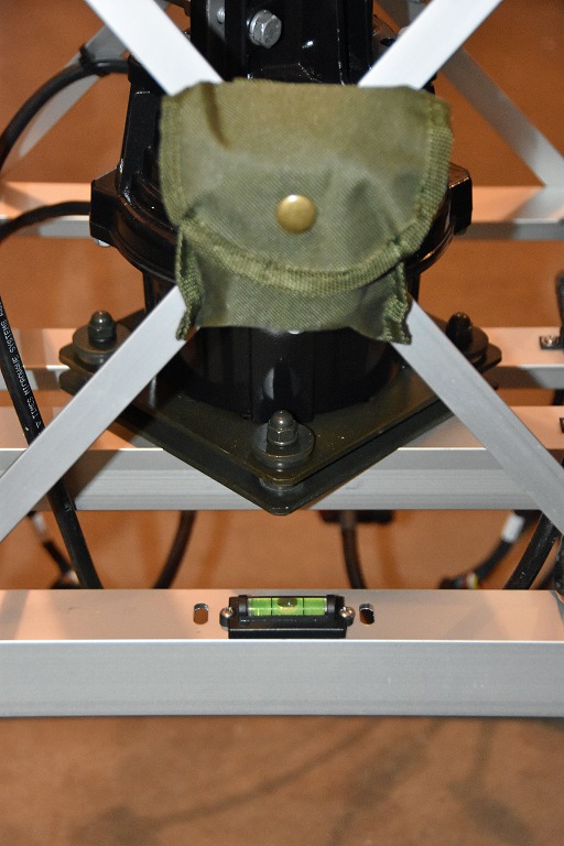
Levels and Compass for Tower Setup
We added a compass and pair of bubble levels to the tower assembly. These additions make it easier to orient and level it during setup. This picture above also shows the Yaesu shock absorbing mount for the azimuth rotator.
Weight Bags to Anchor Portable Tower
Finally, we added a set of weight bags to securely anchor the tower when it is set up in a portable environment. These bags are filled with crushed stone and fasten to the legs of the Glen Martin tower with velcro straps.
Satellite Antenna Assembly and Test
LEO Pack Satellite Antenna Parts
With the tower and rotator elements complete, we turned our attention to the assembly of the M2 LEO Pack. The LEO pack consists of two circularly polarized yagis for the 2m and 70 cm bands.
The 2m Yagi is an M2 Systems 2MCP8A which has 8 elements (4 horizontal and 4 vertical) and provides 9.2 dBic of gain. The 70 cm Yagi is an M2 Systems 436CP16 with 16 elements (8 horizontal and 8 vertical) and provides 13.3 dBic of gain.
Both Yagi’s are meant to be rear mounted on an 8.5′ aluminum cross boom which is included in the LEO Pack. The picture above shows all of the parts for the two antennas before assembly.
Thanks to some help from Jamey, KC1ENX and Mike, KU1V, it took us about a 1/2 day to assemble and test the antennas and both produced the specified SWR performance when assembled and test in clear surroundings.
Assembled LEO Pack on Portable Tower
The picture above shows the assembled LEO pack on the portable tower. We attached a short 28″ piece of mast material to the cross boom as a counterweight to provide better overall balance. Also, we can minimize the strain on the elevation rotator this way. The antennas and the two outer sections of the mast can be easily removed to transport the antenna system.
Satellite Antenna Polarization
2m Circularly Polarized Yagi Feed Point
The LEO Pack yagis achieve circular polarization via a matching network. The matching network drives the vertical and horizontal sections of the antennas with a 90-degree phase shift. The phase shift (and a final 50-ohm match) is achieved using 1/4 wave delay lines made of coax cables. We configured our antennas for right-hand circular polarization.
The choice between right and left-hand circular polarization is not a critical one in our LEO satellite application. This is because most LEO satellites are not circularly polarized. The advantage of circular polarization in our application is the minimization of spin fading effects.
Satellite Antenna Rotator Controls
Green Heron RT-21 AZ/EL Rotator Controller
The final step in the construction of our antenna system was to add the rotator controller and test the computer aiming system. We have had very good results using Green Heron Engineering rotator controllers in our home station so we selected their RT-21 AZ/EL rotator controller for this application. The RT-21 AZ/EL rotator controller is really two rotator controllers in a single box. The rotator control parameters can be independently adjusted. The available settings include such as minimum and maximum rotator speed, ramp, offset, over travel, and others.
Rotator Test Using MacDoppler
The RT-21 AZ/EL Rotator Controller connects to our computer via a pair of USB cables. We run Green Heron’s GH Tracker software on our MacBook Air laptop to manage the computer side of the rotator controller and to provide a UDP protocol interface to the MacDoppler tracking software. The picture above shows the test setup used to verify the computer controlled antenna pointing system.
Configuration and System Test
Mixed OS/X and Windows Software Environment
One challenge associated with selecting a Mac OS/X platform for computer control is what to do about the inevitable need to run Windows software as part of the system. In addition to the GH Tracker software, the WaveNode WN-2 Wattmeter and digital modem software for satellite/ISS APRS and other applications require a Windows run-time environment.
To solve this problem, we use a virtual machine environment implemented using VMware Fusion and Windows 10 64-bit on our MacBook Air Laptop along with Mac OS/X. Using the Unity feature of VMware Fusion allows us to run windows apps such as GH Tracker as if they were native Mac OS/X apps. The picture above shows an example of this.
Rotator Controller and Software Configuration
With the antennas removed from the cross boom, we tested the operation of the computer controlled tracking system. The Yaesu G-5500 AZ/EL Rotator have some limits as to its pointing accuracy and backlash performance. Setting up the combination of the RT-21 AZ/EL rotator controller, GH Tracker, and MacDoppler required experimentation to achieve smooth overall operation.
We finally settled on a strategy of “lead the duck” tracking. The idea here is to set up the rotators so that they over-travel by a degree or two. Also, we couple this with a relatively wide 2-3 degree tracking resolution. This maximizes the overall accuracy of the pointing system. Also, we minimize the tendency towards the constant start-stop operation of the rotators during satellite tracking. Our current configuration for all of the elements involved in the tracking system is shown above.
Next Steps
We can now move onto the next step in our project – the construction of a computer controlled transceiver system. We will cover this element in the next part in this series. Other articles in the series include:
We use cookies to ensure that we give you the best experience on our website. If you continue to use this site we will assume that you are happy with it.


")