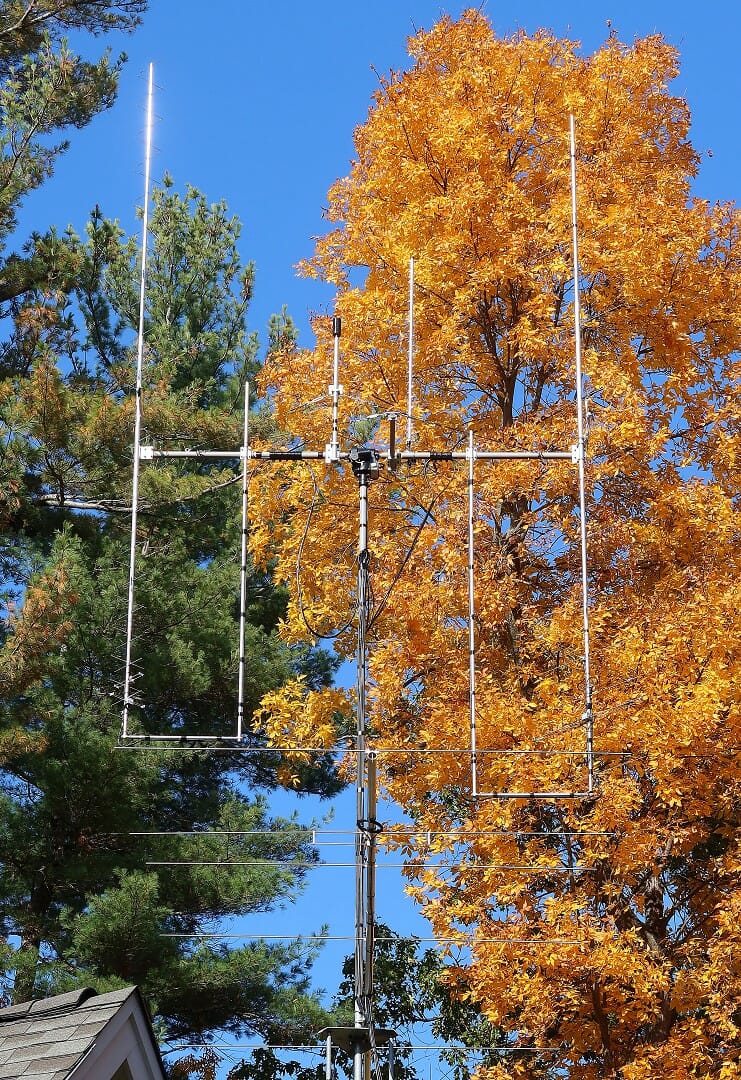
We’ve been making good use of our Satellite Ground Station. Our existing 2MCP14 and 436CP30 antennas have enabled us to make over 2,000 satellite contacts; working 49 of the 50 U.S. States, 290+ Grid Squares, and 31 DXCCs. Our station is also an ARISS Ground Station which enables us to help Schools around the world talk to astronauts on the ISS.
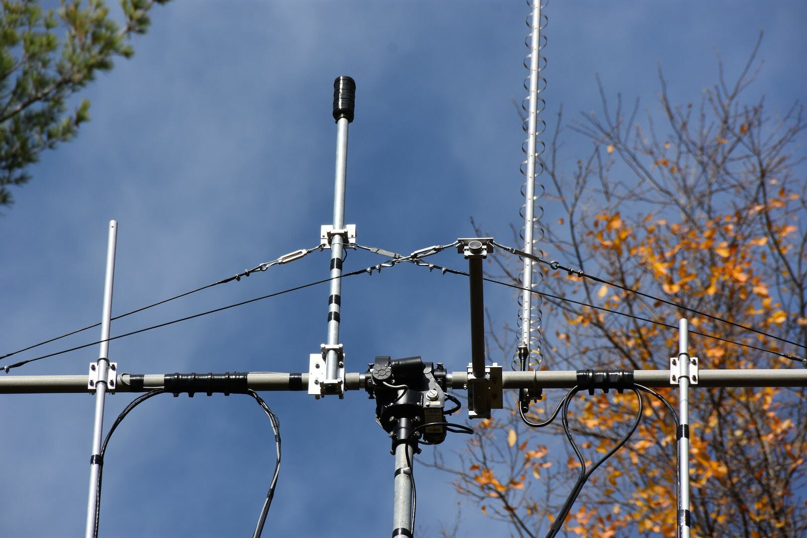
As you can tell, we are pretty active on Satellites so we decided to take our station up a level by upgrading our antennas. We choose larger yagis with booms over 18+ ft in length. The upgrade required us to improve the mechanical aspects of our Satellite Antenna System as well…
We’ve been pretty busy with antenna projects at AB1OC-AB1QB this fall. In addition to building a new EME Antenna System and Station, we’ve also been working on upgrading our Satellite Antennas.
The article above covers the construction and adjustment of the new antennas. It also covers several custom enhancements that we made to our satellite antenna support system.
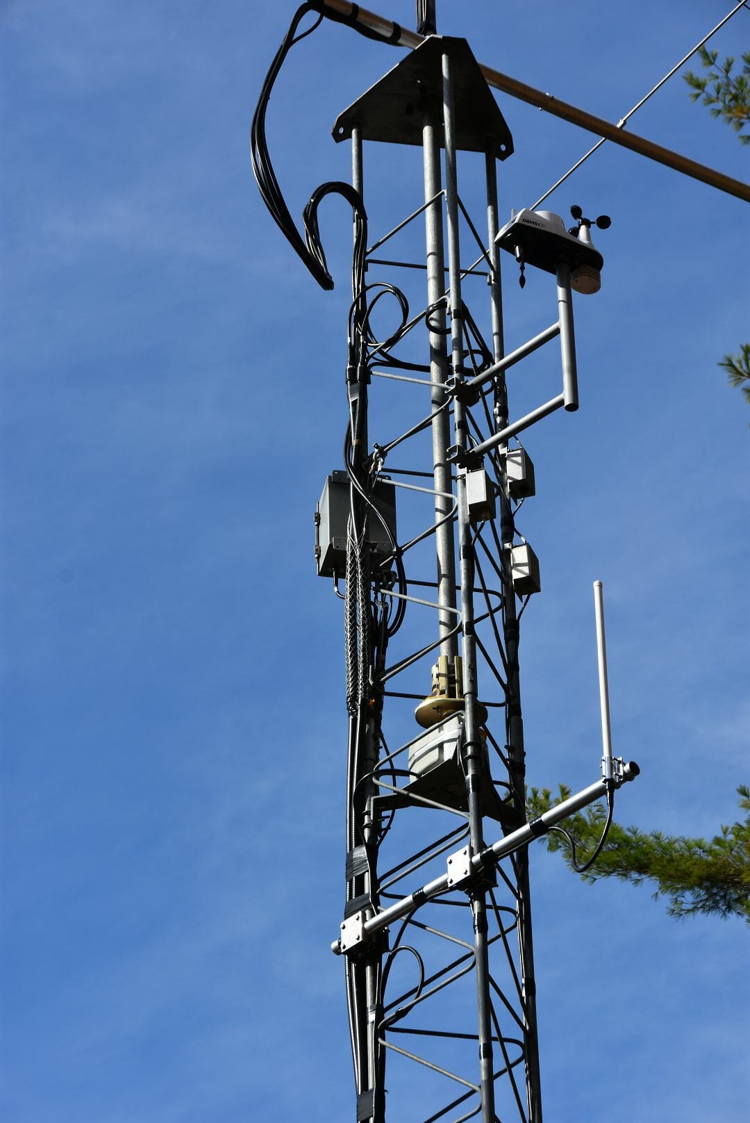
Aircraft Tracking Antenna System Addition
Satellite Tower Infrastructure including ADS-B Antenna
We also added an outdoor antenna for our FlightAware ADS-B Tracker as part of the project. ADS-B is a relatively recent aircraft tracking system. Our new ADS-B antenna has increased our Tracker’s contribution to the ADS-B network considerably.
If you’ve ever wondered what goes into building and putting up a high-performance satellite ground station, take a look at the article. The ideas shared there are applicable to the construction of any VHF and above antenna system – especially those that utilize elevation rotators and thus require balancing.
Software is a big part of most current EME stations. The JT65 Protocol, which was created by Joe Taylor, K1JT, has revolutionized EME operations. It has made it possible for modest single and two yagi stations to have fun with EME…
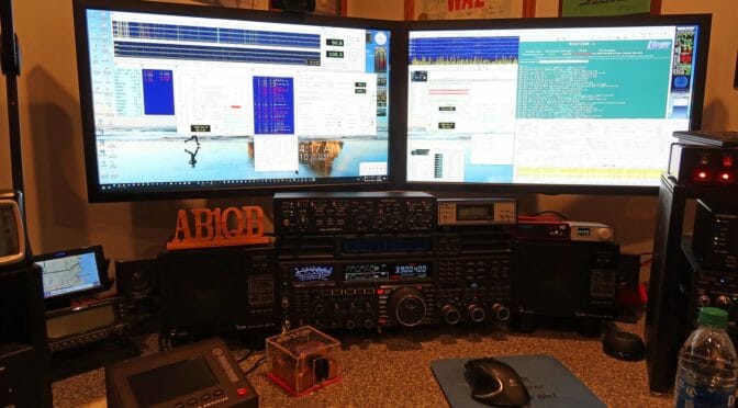
Operations using EME or Moonbounce communications is all about software. Every station’s software architecture and configuration is a little different.
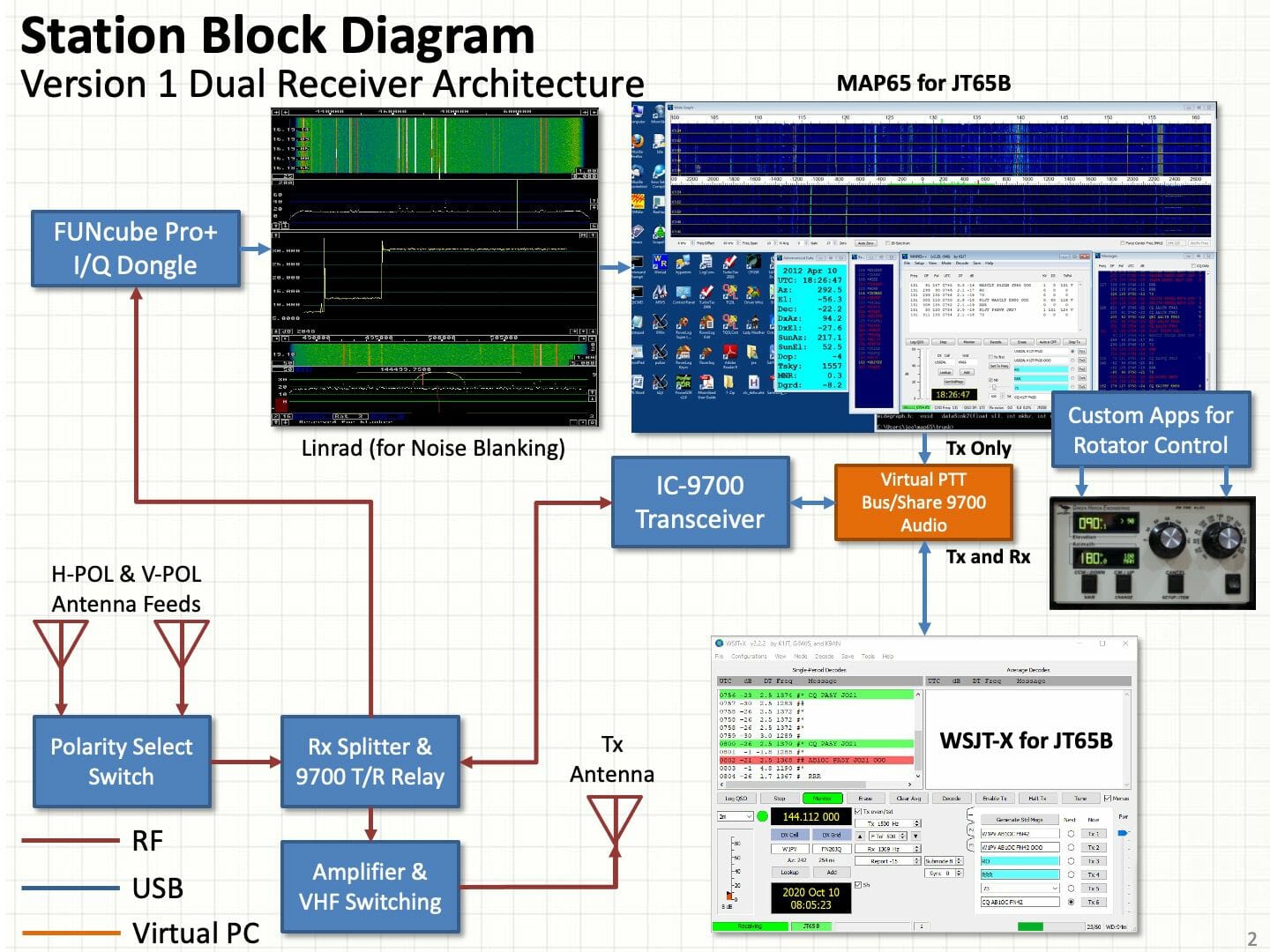
Station Software Block Diagram – Phase 1
We recently put together our software suite for our new 2m EME station. Our setup features multiple JT65b digital decoders, automatic tracking of the Moon, computer logging, and some useful web-based tools that make finding QSOs easier.
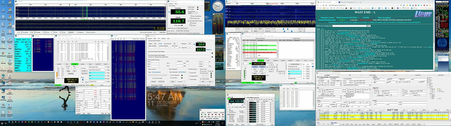
EME Station Software Operating Environment
Our Phase 1 station configuration is mostly about integrating all of the components in our setup, sorting out operational issues, and learning to use all of the new software and hardware in our new Station.
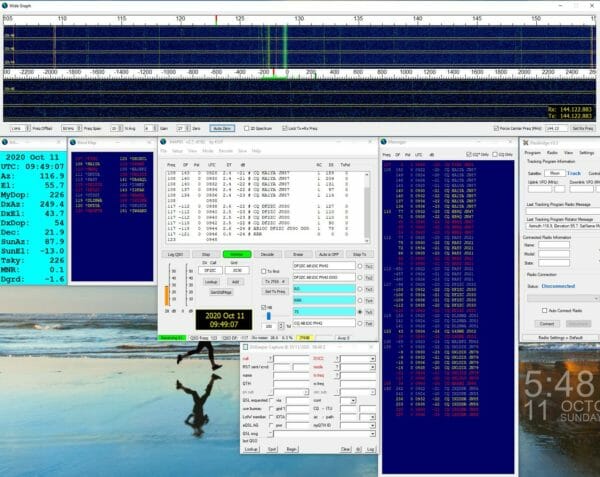
MAP65 Software
Our primary software application is MAP65. This program can decode all of the signals on a given band at the same time. This is very useful during an EME Contest and for finding contacts during day-to-day operations.
You can read all about our software setup for our station via the link above.
It started over 2 years ago when my wife and I decided to downsize and chose a home for us to enjoy our final years. I was also looking for a home that had a view and would allow a ham radio tower to be erected.
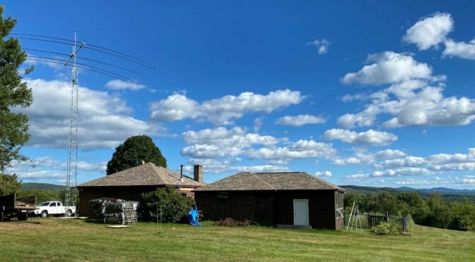
Antenna and Tower with a View
My home and property
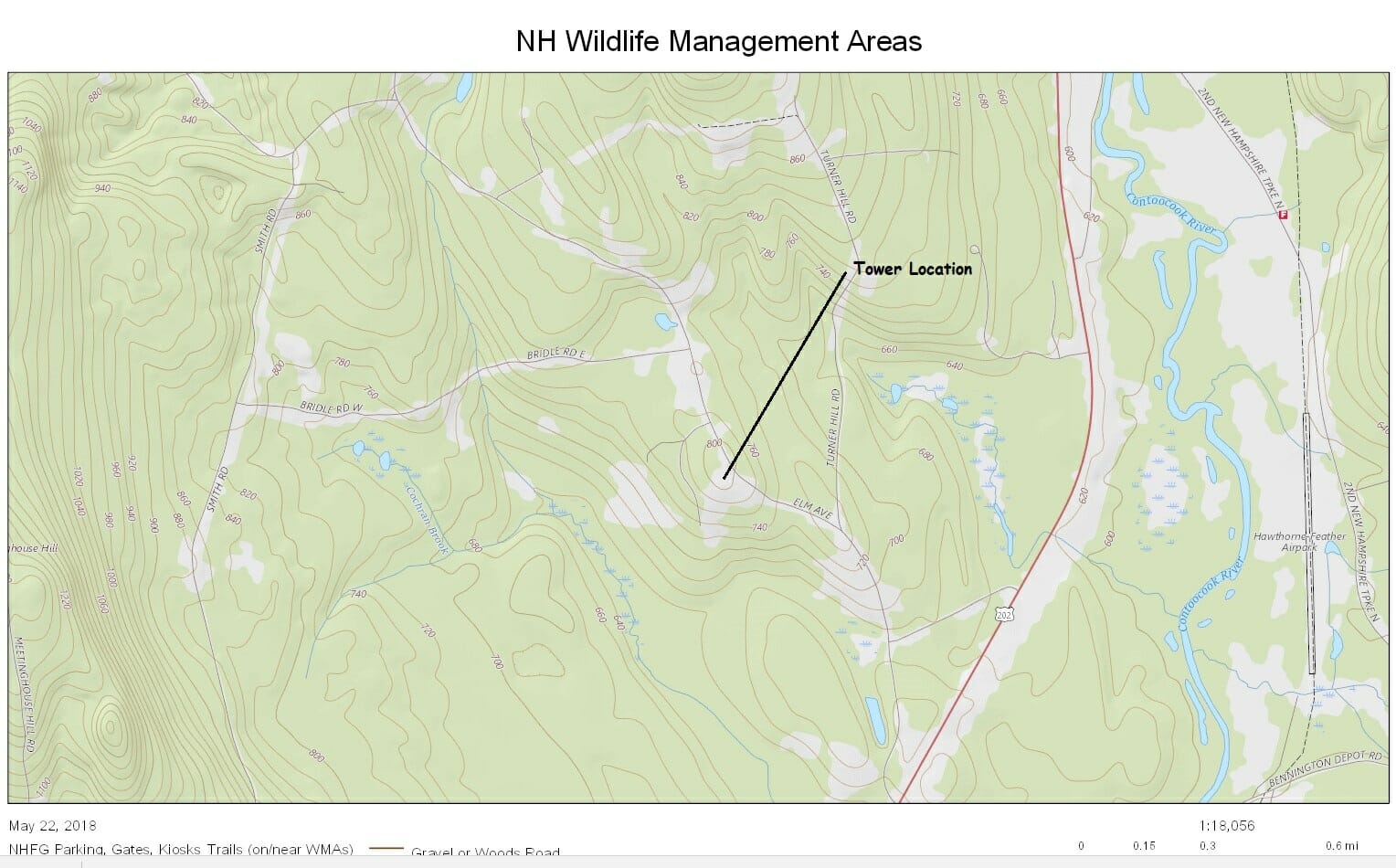
My house is at 810’ above sea level. I have exceptional views South, and it extends both East and West. I’m going to describe the home/tower exposure because it’s important for later.
To the North and East the tree line is about 100’ away and the ground slopes away about 40’ down North and a 60’ slopes down to the east. To the West is nothing for 300 yards and slopes down over 160’. To the south, there are 300 yards to the tree line which is below the line of sight and slopes down 160’. Otherwise, we can see 40 miles south and 2 miles west and east. To date, as a weather front comes through, we have experienced winds at around 45 MPH. You can see from the photo that the view is spectacular. I included a topo of where the house/tower is located, from this you can see the hilltop location.
Topo of Tower Location
Antenna Selection: Vertical
One of the first things I was told about selecting an antenna was to wait until you can afford a SteppIR antenna. It made sense because you don’t have to worry about VSWR. The antenna will change the element length to match the frequency currently tuned to. I have a Stepp BigIR Mark IV vertical which covers 40 Meters through 6 Meters. This antenna works great for FT8 also. You just need to make sure you have lots of ground radials. I have 32 40’ radials.
Antenna Selection: Horizontal
I had a Mosley Classic 33, 10M, 15M 20M, tuner for voice, auto tuner had fits if I wanted to do FT8. I was looking for something that would provide good results for low sun cycle propagation. That meant wanting 20M and 40M and the other bands would be nice when the sun cycles improved. I focused on 3 elements vs 4 elements. So, I settled on the SteppIR DB18, because I could not justify a $2000 increase for an antenna that gave less than 2dB more gain. Also, this antenna allows me to flip the antenna 180 in like 2 seconds, make the director the reflector and the reflector the director
Mast: ¼” thick walls, 17’ long, 2” at the base and 1 ½” at the top. 5-foot wind load buried 4 feet into the tower
Town Requirements
Some towns only allow amateur radio towers to be 50’ while other towns allow 70’. Antrim initially had 70’ for amateur radio and if you wanted taller than that you had to follow the commercial tower requirements. It is now whatever the FCC / State requires. When I filed for the permit the inspector stated that a building permit is not required for amateur radio towers, but he did look at the request to ensure there was no safety issues, ie., could the tower fall on a neighbor’s house, public roadway, etc. and that I was more than 50’ from the roadway and 25’ to the property line. I had also submitted a copy of my Amateur Radio License, which he thanked me for and requested that I submit my renewal when I do my 10 year renewal. He then filed all of it into the town records.
It doesn’t hurt to talk to your neighbors to ensure that they will not be upset at you for putting up this (non-hams) ugly tower. I did this and we agreed that if I put the tower towards the front of my garage it would not be as visible to him.
My Tower Requirements
To start with you have to have a wish list in mind. Mine was as follows:
DIY (do it yourself) Install
No climbing
Fold Over at the base
Would be nice to be able to hang an 80m inverted Vee (65’)
Tower Selection
The easiest way was to start looking at the Rohn catalog. They have a section in front to get you started. They start with understanding TIA-222 revision G. It goes through Classification of the antenna structure, HAM’s will always be Class I. Next is the EPA (Effective Projected Area) or area (size) of your antenna, don’t forget the mast and the rotor. Next is what is your exposure, folks in the flatlands of Ohio(?) will be exposure C, here in New Hampshire where we have mostly 100’ trees around most homes and will be Exposure B. Anyone living along the coast fits the last exposure D. The next category is what snagged me. Topographic category, remember the section above where I pointed out the terrain of my house. I got snagged as a category 3 site, at the top of a hill which means you must multiply the wind load by 2.3. Damn, that’s 10.1 + 1 + 1.5 = 12.6 * 2.3 = 28.98. That’s a huge value.
So now I set out to search for an antenna company to meet my wish list. Remember, I’m not interested in climbing a tower. There are lots of towers out there, but I needed something with the ability to handle 29 EPA (that’s TIA-222 talk for wind load). ROHN towers did not meet my wish list of no climbing towers. Universal towers have an aluminum tower rated for 35 sqft at 110 MPH winds. Next was Heights Towers, they had aluminum towers rated by the exposure that would meet the requirements. I love the features that they offer and the fold-over kit. But not the cost. I’m retired and don’t make a lot of money, so I opted for the Universals tower. When looking at these towers don’t forget the cost to ship it to you. There is a big difference shipping from Florida to NH vs Michigan to NH (more than double).
Tower Height
I read in QST “The DR Is In” article where someone was asking how high does a Yagi antenna needs to be? His reply was a Yagi only needs to be 43 feet off the ground. I also know that angle is related to the topology of where the tower is installed. Therefore my 40-foot tower is great for my topology.
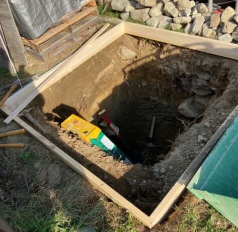
The base for a Standalone Tower
Tower Installation
Did you know that digging a hole for a self-supporting tower is a really BIG HOLE. 5 feet by 5 feet by 6 feet deep? It took me 2 weeks of digging a couple of hours per day to dig the hole and I move the dirt away. The last foot was this stone and stone dust mixture. I only got down a couple of inches per day. Lessons Learned don’t wait to make the bottom of the hole 5’ by 5’, because every shovel full is going up over 6’. Why not a backhoe? They don’t want the dirt disturbed around the hole. Besides I wanted to DIY. It takes 6 cubic yards of cement to fill a 5’ x 5’ x 6’ deep hole. I waited almost 2 weeks to raise the tower/antenna. The concrete was nice and hard. I actually built the antenna during the curing time.
Another lesson learned, concrete in the center will shrink, next tower (HaHa) don’t level it, instead have the center higher than the sides and exaggerate it.
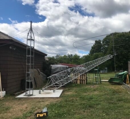
Raising the tower.
Tower Raising
I had some older tower parts and I thought I’d use them as a fulcrum. On the back of the truck is a hand winch. Went high enough on the tower (halfway to the top of the actual tower) to anchor onto the back 2 legs. The fulcrum didn’t respond well so I called a safety assessment time out. We lowered and only went up about 12’ and only used a 10’ section of the tower. This ended up working much better but the winching was much harder. I’d like to redesign the fulcrum and swap out the hand winch with a power winch.
Cable Selection
I choose to use LMR-900 to run from the entry point to the top of the tower. Worked out to be 110’. The top of the tower to the antenna is 10 feet of LMR400, from the house entry point to the back of the radio is 15’ of LMR400.
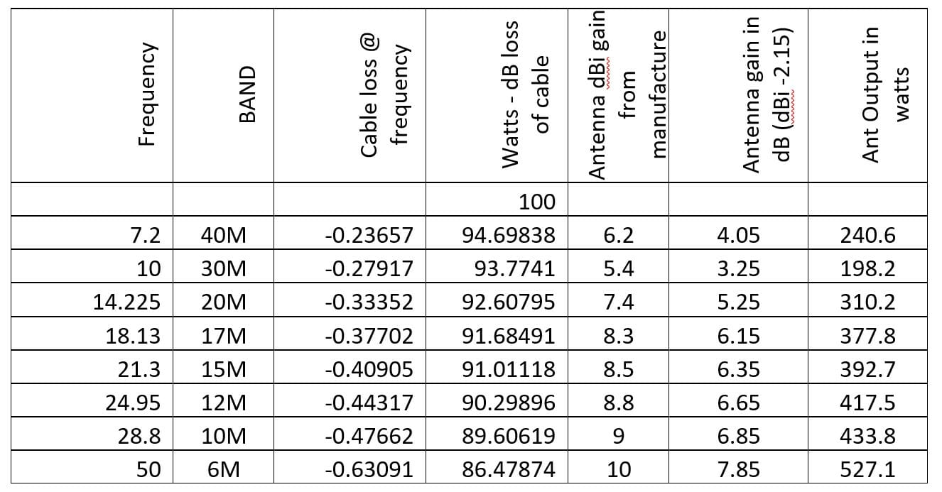
Did you ever want to know how much power you are radiating in the direction of your wonderful Yagi? First, you must determine the power you’re going to lose through the cable at the frequency you’re transmitting at. Next subtract the cable loss from the power out of your transmitter, say 100 watts. Then look up your antenna gain, convert dBi to dB and multiply that by how much power you are providing the antenna at that frequency. The results will be how much transmit power you are sending in a direction. This whole exercise is based on dB and Transmit Power or dB loss/gain. I had to convert things back and forth to get the right power from dB gain.
Antenna Power Out by Frequency
It’s the little details that are missed sometimes. Making drip loops to ensure that water doesn’t run down your cable and right into your connector or control box. Have enough cable for the rotor to turn 360 degrees. Have enough cable to fold down the tower.
Tower Completion
I grounded the tower on all three legs. I used 4 gauge bare solid copper wire from the tower leg to ground rods, 4’ from the tower legs. I wanted to run the RF cable down the center of the tower. It made sense that lightning would travel on skin effect (tower legs) and not on the RF/control cables to the ground. I did not have a good enough method to hold the cable suspended in the center of the tower. A failure of my ingenuity.
Also, at the entry point into the house, there is a ground rod that I have an RF lightning arrester attached to. There are no lightning arrestors for the control cables. This ground rod is also grounded to the point of entry ground rod and is the ground point for all of my radios and support equipment.
At the very top of the tower, I have a wind gage (anemometer) but it doesn’t give me the wind direction. It’s a very simple device. It uses a bicycle reader and the anemometer at the top. Just counts revolutions, it gives you current, average and MAX speed. It was all I needed, I’ve tried others and they didn’t last very long or did not give an accurate wind speed.
Now the SteppIR doesn’t help me for VHF/UHF and you probably asking why didn’t I put a VHF/UHF antenna on top of the tower. I have a CREATE Log periodic in my attic on a rotor. It is able to do a full circle in less than 60 inches. My cable run is very short, so power loss is kept minimal. Covers 50 to 1,300Mhz and has 10dBi gain. I have this going to an antenna switch to go to multiple radios.
So far, I’m getting great reception in Europe. Had contacts with Japan, South Africa and have been hearing Australia and Indonesia. One of the reasons I love FT8 is it labels the contact’s country of origin. Just wait as the sun cycle improves, so will my contact log.
The next project is to complete a wiring diagram of my shack. I’d like to be able to visually know how everything is wired together.
Hope this helps you with your design and planning process for your dream tower.
It would be nice if there was an Elmer antenna and tower board to submit your ideas to get feedback.
We use cookies to ensure that we give you the best experience on our website. If you continue to use this site we will assume that you are happy with it.