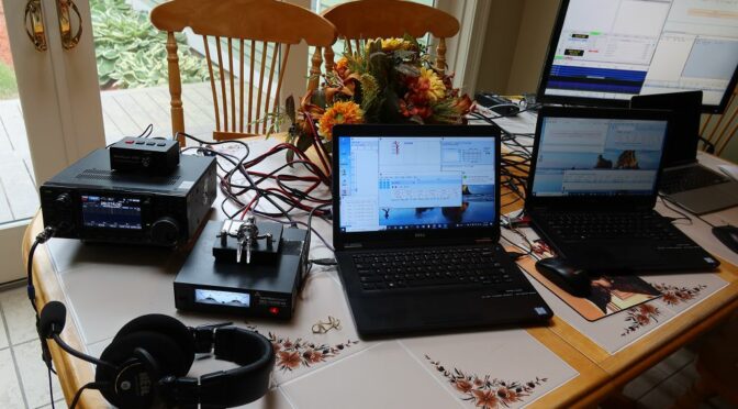
Lee KC1GKJ, Joe AC1LN, and Fred AB1OC got together today to configure our radios and loggers for 2022 Field Day and do a Field Day Test. We focused on the 80m/15m/10m station as it is the most complicated of our four planned stations at Field Day.
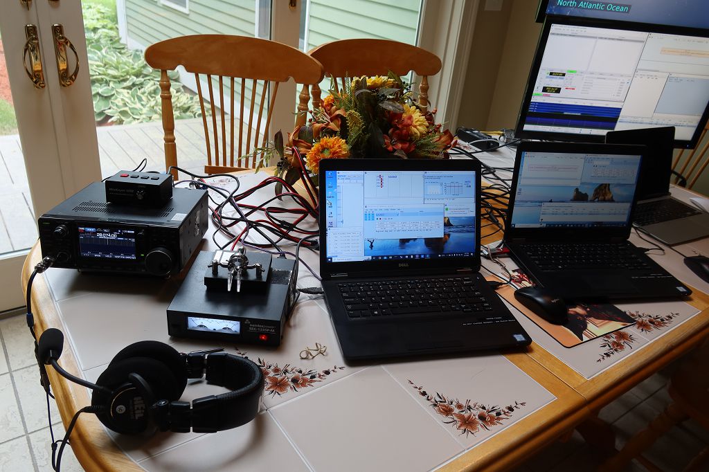
Field Day Station Setup – 80m/15m/10m
We also configured a second computer running N1MM+ for use with the 20m station. We used both PCs to check out log sharing,
Joe AC1LN and Lee KC1GKJ
which will be used at Field Day. Thanks to Joe and Lee for the great work to prepare NARS for Field Day 2022 and complete our Field Day Test.
This article is an adaptation of a presentation I gave for Nashua Area Radio Society Tech Night on February 8, 2022.
Want to learn Ham Radio operating skills and technical skills? We hold a monthly Tech Night Session as part of our mission to help our members develop and expand their Ham Radio-related technical knowledge. NARS holds a Tech Night meeting every second Tuesday of each month. We record our Tech Night presentations, and they are available online for our Members and Internet Subscribers.
Membership Meetings and Tech Nights
Our Membership Meetings are held on the first Tuesday of each month. You can find out about our meetings here. We have a variety of speakers who share interesting presentations about Amateur Radio at our meetings. We invite you to attend one of our meetings. This is a great way to meet our members and learn more about what we are doing. Check out our recent presenters below. We’re looking forward to having Bob Heil present at our March 1, 2022, meeting coming up. Please join us.
Membership Meetings
Antenna Evolution
You got your license and want to get on the air. The next step is to get a radio and an antenna installed. I started with a very good radio, the IC-7300. My first antenna was a Chameleoncha-emcomm-ii end-fed antenna 60′ long installed as a sloper in a pine tree in the back yard. This setup worked but not very well. I was able to make QSOs in the eastern part of the US out to the Mississippi River or so. I was on the air but needed more and so I began my quest for bigger and better antennas. It is now five years later, and the quest continues.
First upgrade
I began my search for a better antenna by researching the alternatives. The budget was a consideration and my physical situation at home was another. I took note of where the trees were located on my property and quickly saw that an Off-Center-Fed-Dipole would fit the situation very well. I read that it is best to focus attention on improving antennas before spending resources on amplifiers and fancy radios and intended to follow that path. As a new ham, I decided to purchase a proven commercial solution rather than attempt to homebrew something on my own. I bought a Buckmaster 7 band low power OCFD. It is 135 feet long with one leg 45 feet long and the other 90 feet long. This matched the locations of two trees on the property with the feed point directly over my roof peak.
20 feet OCFD
What next?
This iteration of the Buckmaster was quite an improvement over the short sloper and I was now coast-to-coast! It was in the summer of 2018 at the bottom of solar cycle 24 so conditions were poor. This setup was OK, but weak in a pileup and I wanted to go to the next level. Fortunately, the next level did not require a new antenna. It only required that I raise the feed point of the current antenna to 1/2 wavelength on 20 meters to have it perform at its potential.
33 feet OCFD
Here is a picture of the Buckmaster optimized for my QTH. The feed point is up at 33 feet high ~1/2 wavelength for 20 meters. The ends of the antenna are 15 and 18 feet high, giving the antenna an inverted V configuration with the angle at the top around 120 degrees. Performance with this antenna and 100 watts from the IC-7300 was very good. At the bottom of the solar cycle, I worked all states and made my first 80 DXCC contacts. Still, I wanted a better station and my research informed me that the next step was a beam antenna.
Why choose a Wire Beam Antenna?
Wire Beam Pros
Lightweight
Low wind load
Possible to utilize light masts and rotators
Can be excellent choices for towers or masts which can telescope, retract, or tilt
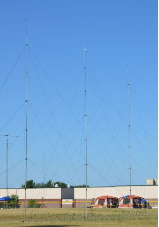
The wire beam is a very high performance, but it cannot change direction. It is possible to rotate it 180 degrees electronically with stubs and relays. In this example NARS N1FD club station was located in NH, so we oriented the beam at 260 degrees and had coverage for all of the USA. Max Gain Systems has this picture on their website, they sell the 50-foot fiberglass masts used here.
Delta Loop
Delta Loop PU1JSV
I have a little more than 11,000 QSOs in my log so far. Only 3 or 4 people had pictures of Delta Loop beam antennas on their QRZ pages. This picture is an excellent example from PU1JSV. There are a few commercial options available in Europe, but I haven’t seen any in the USA for HF bands. For that reason, I would classify these as mostly DIY. There is a disadvantage with this design in that it has a more 3-D wind profile so may be more vulnerable to the elements.
Quad
4 Element Quad Antenna-LA4UOA
Similar to the Delta Loop style beam antennas the Quad or Cubical Quad antenna does not have much commercial availability in the USA. It is very popular, and I found many examples of it in my QRZ logs. This example from LA4UOA in Norway works great. I’ve had 7 QSOs with Tor on it. Like the Delta Loop Beams this antenna also has a 3-D wind profile so may be more vulnerable to the elements.
Moxon Beam
Wire Moxon M1DAZ
Here is an excellent example of a wire Moxon. They are usually 2 elements. This style is widely available in aluminum commercially and there are many parts suppliers and plans available for DIYers to construct one successfully. The design is simple, compact, and lightweight.
Broadband Hex Beam
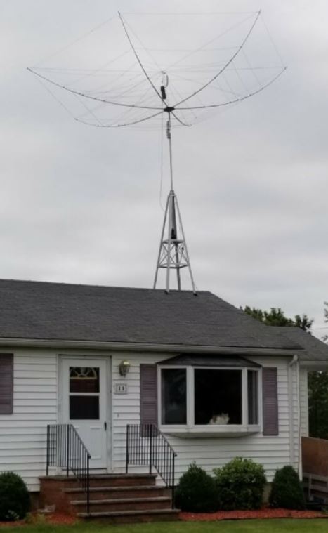
Hexbeam AC1EV
There are many different commercial options for Hex beam antennas. Parts and supplies for DIY projects are also widely available. There are even websites with free detailed plans for constructing a hex beam. Typically, each band is 2 elements. Some have options for 40 meters, but those are usually only bent dipoles. Hex beams with a 20-meter band included are relatively compact, around 22 feet in diameter.
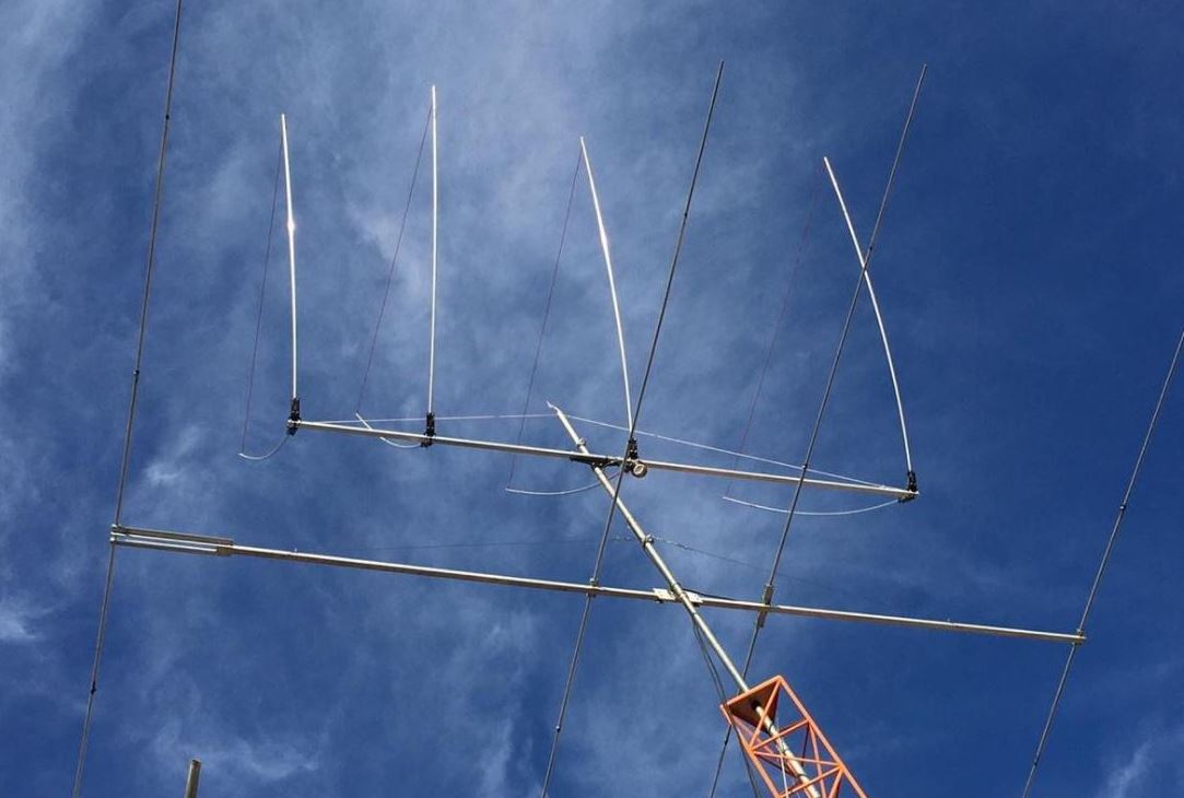
Spider Beam
Spiderbeam AC1EV
Spiderbeam was founded in the year 2000 by DF4SA. The company is from Germany, and they also have a US distributor and online shop here in the USA. The original spider beam was a full-size lightweight triband yagi for 20-15-10m, made from fiberglass and wire. Further development yielded a complete 5-band-beam (20-17-15-12-10m), a WARC version (30-17-12m), and several other configurations. Several full-size monoband beams are interlaced on one boom with negligible interaction. The HD 5 band version of the antenna is around 33 feet in diameter and weighs only 25 lbs. Spiderbeam offers a kit assembly service that delivers a pre-assembled antenna kit, with the wire elements, guy lines, and balun prepared to make assembly go much faster. They also provide complete instructions for a DIY’er to build the antenna at no charge.
Hex Beam Size vs Spider Beam Size
Hexbeam v Spiderbeam Size
The picture above shows the Hexbeam and Spiderbeam antennas on the ground during construction.
Hexbeam to RoofWalking the Spiderbeam
The two pictures above show part of the transition of the antennas from the construction on the ground to mounting on the roof or mast. You can see the relative size of the antennas. The Spiderbeam is around 850 square feet, which is definitely the largest thing I have ever picked up.
Get it in the air – Mast Selection
Chimney Mount
Chimney Mount
What about using the chimney to support a mast? If you want to consider this, be aware that even a brick chimney is not necessarily all that strong. The brick is a façade and unless you are confident of the structure behind the bricks, I would be cautious about mounting a hex beam mast against it. A TV antenna is fine, but a wire beam antenna is in a different category from a weight and wind load standpoint. My chimney on the left could hold the Spiderbeam but we get ice in winter regularly and it could cause substantial damage to the house if it failed. That said, on the right is an example of a chimney-mounted Hexbeam.
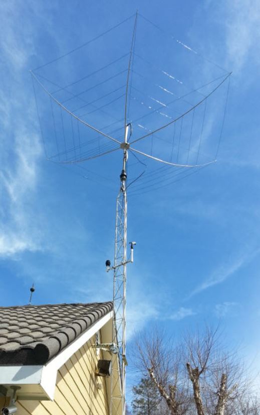
Roof Top Mast
Roof Top Mast
I used a Glen Martin 8-foot tower to mount my Hexbeam on the roof of my home in Massachusetts. W8IO is a manufacturer of similar towers and might be a good source for them if you are interested in mounting your antenna this way. These short towers are very sturdy and, on a roof, in combination with a proper mast can be a good solution for mounting your beam antenna at around 33 feet. It is important to pay attention to the manufacturer’s admonitions about properly bracing beneath the roof decking and sealing against leaks.
Push up mast
Push-up Mast
With a push-up mast, the best arrangement is to locate the rotator at the bottom and rotate the mast as well as the beam. This keeps the load on the mast at a minimum. Many push-up masts have floating guy rings that make this possible. My selection was a Spiderbeam Aluminum Telescopic Mast 14.5m HD (47ft). It is a robust mast for permanent installation and is specifically rated to extend the mast to a full height of 14.5m (47ft) with the 5 band HD version of the Spiderbeam antenna. The additional height may improve the performance, especially on 20 and 17m due to the lower take-off angle.
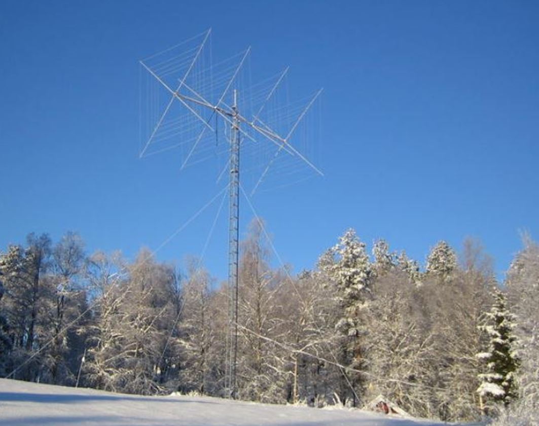
Conventional Tower
Conventional Tower
If you already have a tower or got one from a fellow ham and don’t mind the issue of digging the hole, the rebar and concrete, there is not a thing wrong with using a conventional tower. They probably are a better choice than the other choices above but usually cost a lot more. This may be beyond the skill set of many hams as a DIY project. Here is a beautiful example of a house bracketed tower with a Hexbeam.
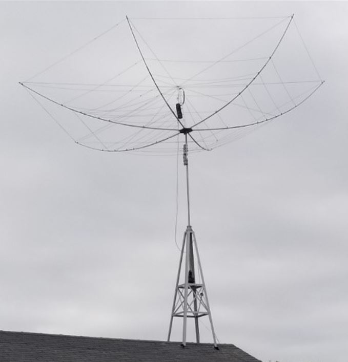
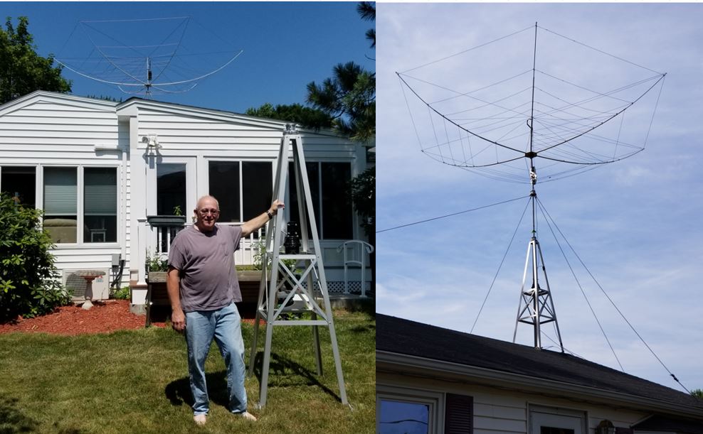
My Wire Beam Antennas – Hex Beam
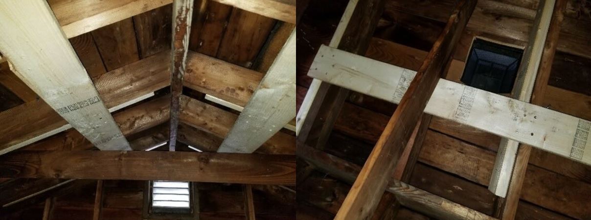
Reinforce Rafters
The first step prior to installing the Glen Martin tower was to reinforce the rafters under it to take any additional strain it would cause. I sistered the rafters with 2X8s and then braced them horizontally with additional 2X8s connected to 5 rafters.
Hexbeam with Tilt Plate Ready to Raise
I purchased the K4KIO model Hexbeam and ordered it on a Monday. It was delivered on Thursday. I assembled the antenna in my driveway, with the central hub mounted on a short section of chain link top rail stuck in an umbrella stand. Assembly was simple. I put the antenna on the old tripod from the dipole for temporary use until the parts were installed. The height from the ground to the peak of my roof was 15 feet. I ordered the 8-foot Glen Martin tower to mount on the roof. I also ordered a Hex Lock Tilt Plate, which adds a foot of height. The main mast extends 6 feet from the top of the tower and there is a small section from the tilt plate to the antenna. The antenna is close to 3 feet deep, which puts the 20-meter segment at 33 feet or ½ wavelength exactly.
How Does It Perform?
Hexbeam at 33 feet
The first day began with Frankie VP2MNI in Monserrat having a QSO with Masa JE1LET in Japan. When I heard that Frankie was with a Japan station I rotated there and was able to hear Masa at a 56. When they finished their QSO I called out and Masa replied first try!
The last contact I made was KH7XS. Normally this station generates big pileups, but for some reason, everyone had gone to 40-meters, and we were almost alone on 20-meters. We had an 18-minute QSO at 59 for most of it. Japan in the morning and Hawaii at night, I never had a day like that before the hex beam.
These results were not typical, and I haven’t had any QSOs with Japan since then but from Australia to Alaska, Europe to South Africa, and points in between it is always strong.
My Wire Beam Antennas – Spider Beam
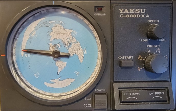
Preparing the base for the mast
Prepare the Base
The Yaesu 800DXA Rotator that will rotate the mast and antenna is mounted to a steel pipe buried and cemented into the ground. While I waited for the concrete to cure properly, I constructed the antenna.
Beginning Antenna Assembly
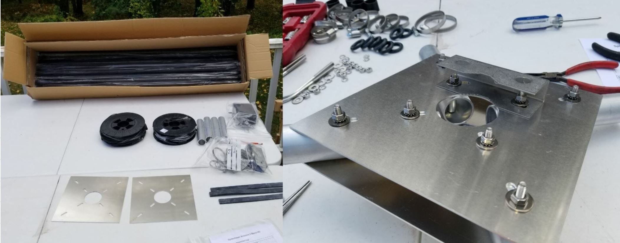
Beginning Spiderbeam Assembly
The box contains 20 fiberglass tube segments along with all the other parts required to assemble the antenna. The right shows the Spiderbeam Center Joint. The wires are loaded on the spools in the order you need to have them which helps a lot. The wires are close to the lengths required but the driven elements do need to be tuned for each situation.
Completing Antenna Assembly
Mount Spiderbeam on Mast
The Spiderbeam is constructed on the topmost element of the telescopic mast. After carefully installing the wires and balun the top element needs to be joined to the rest of the mast. With each of the spreaders 16 feet long, it is an awkward object to maneuver. The spreaders are quite strong and with the use of a ladder, it was simple to connect it to the mast.
Stepping the Antenna and Mast on the Rotator
Mount Mast on Rotator
I connected the combined antenna and mast assembly to the rotator with the help of a ramp, two jack stands, and the ladder. Notice the ladder is securely strapped to the ground and does not move at all. By resting the mast on the top rung, I was able to guide it into the rotator. I needed to raise the mast adaptor to fit properly, and the chisel made that simple. I secured the whole thing to the ladder while I installed the bolts for the rotator.
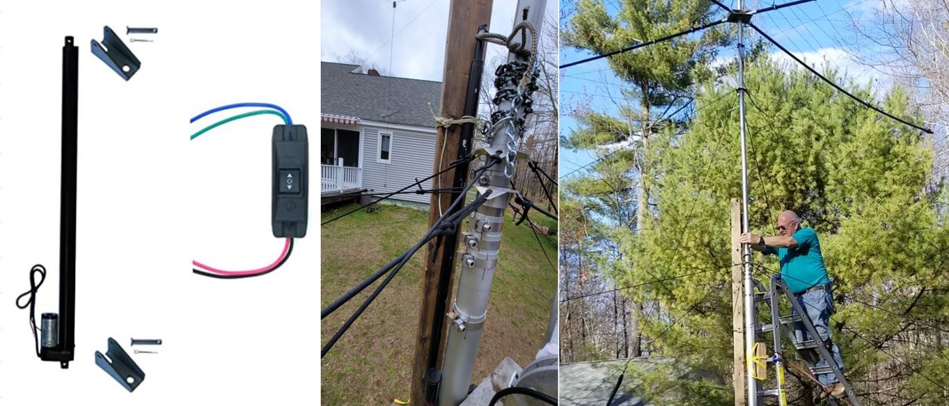
Linear Actuator
Linear Actuator
I purchased a 12-volt linear actuator to use to raise the antenna. It has a 30-inch stroke and can lift 225 lbs. I attached it to a 10-foot 2X4 and attached it to the mast with a length of chain that I sprayed with liquid rubber. I powered it with a 12-volt jump-starter that had a cigarette lighter plug. This allowed me to extend the mast 18” to 24” per cycle. Each cycle included wrapping the chain, taking the mast under tension, loosening the clamps, raising the mast, tightening the clamps, releasing tension on the chain, moving the chain, and adjusting the 12 guy lines to give enough slack for the next move, while stabilizing the mast. It was a slow process, but safe to do on the ladder with my feet only about 5 feet above the ground.
Raising the Antenna
Raising the Spiderbeam
At various stages during the lift, I needed to manage the coax and attach it to the mast with enough slack so it would not tangle with the 12 guy lines. I also preset the rotator so it would be pointed north on its controller and kept the antenna aligned to the north as well.
How Does It Perform?
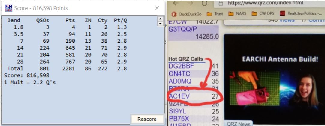
Score and QRZ
The Spiderbeam performs quite well and takes advantage of the favorable terrain at my NH QTH. I have generated numerous pileups during casual operating and had great results in contests and 13 Colonies. Below is my 2021 CQ WW DX SSB score. I made more QSOs on 10 meters than any band and I was able to run and hold the frequency on 10, 15, and 20 meters.
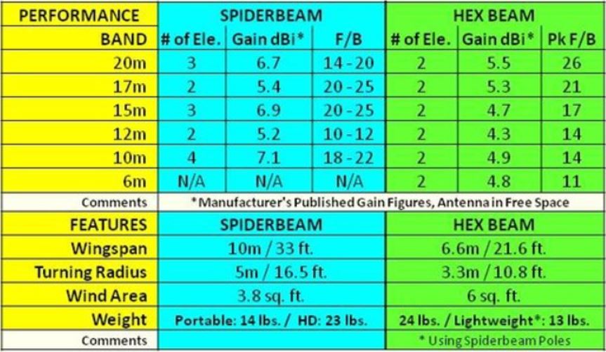
Spiderbeam vs Hexbeam
Spiderbeam v Hexbeam
Here is some additional detail from Spiderbeam.
Spiderbeam Detailed Specifications
Click here for even more details on Spiderbeam’s performance.
Click here for even more details on the K4KIO Hexbeam performance.
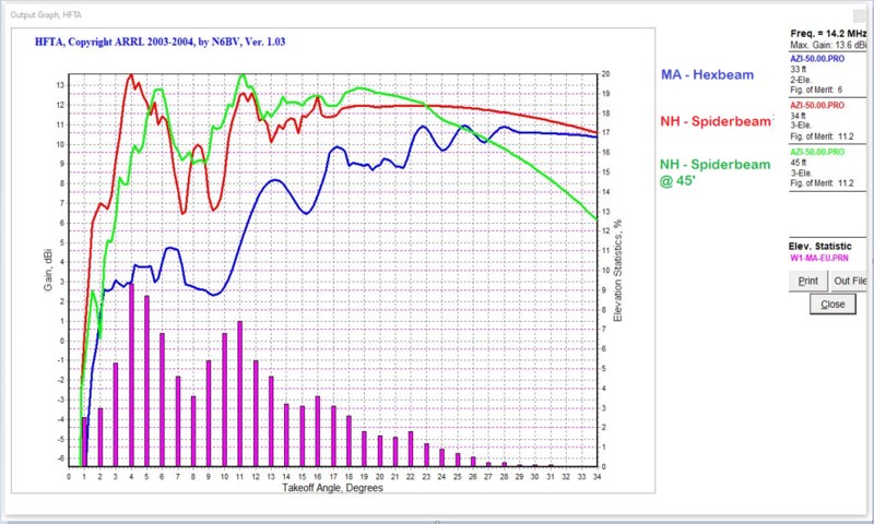
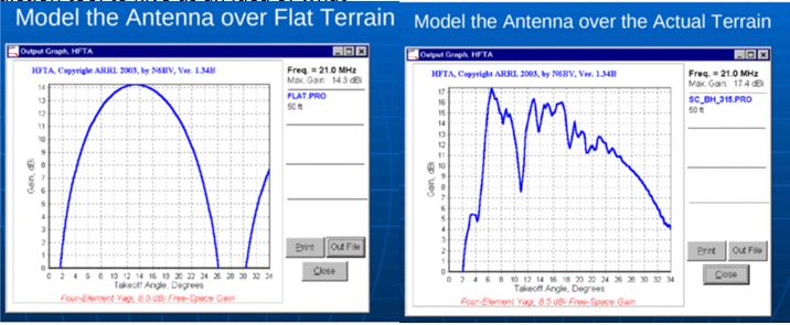
HFTA Comparison
HFTA Comparison
The above output graph from HFTA compares the Hexbeam and Spiderbeam at 33 feet The antennas are pointed at Europe ~50 degrees. This one is theoretical and does not take any terrain into account. It shows around 1.5dB advantage for the Spiderbeam on 20 meters. This is consistent with the previous chart.
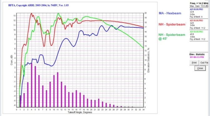
Terrain Based Results
This chart shows the real-life analysis including terrain and shows a dramatic advantage of the Spiderbeam over the Hexbeam at my 2 QTHs.
Conclusions
There are many options for wire beam antennas.
Hexbeam has many competing commercial solutions and can be homebrewed
Spiderbeam is a commercial product and can also be homebrewed
Moxons, Delta Loops, and Quads have limited commercial availability and are often DIY.
Hexbeam and Spiderbeam may be the maximum gain antenna a single person without a crane or man lift can erect.
HFTA stands for High-Frequency Terrain Assessment. Some documentation refers to it as High-Frequency Terrain Analysis.
HFTA is a software tool that generates the vertical radiation pattern of horizontally polarized antennas taking into account the profile of the surrounding terrain. The irregularity of local terrain has a profound effect on vertical radiation patterns. Note that HFTA does not compute radiation patterns for vertically polarized antenna radiation.
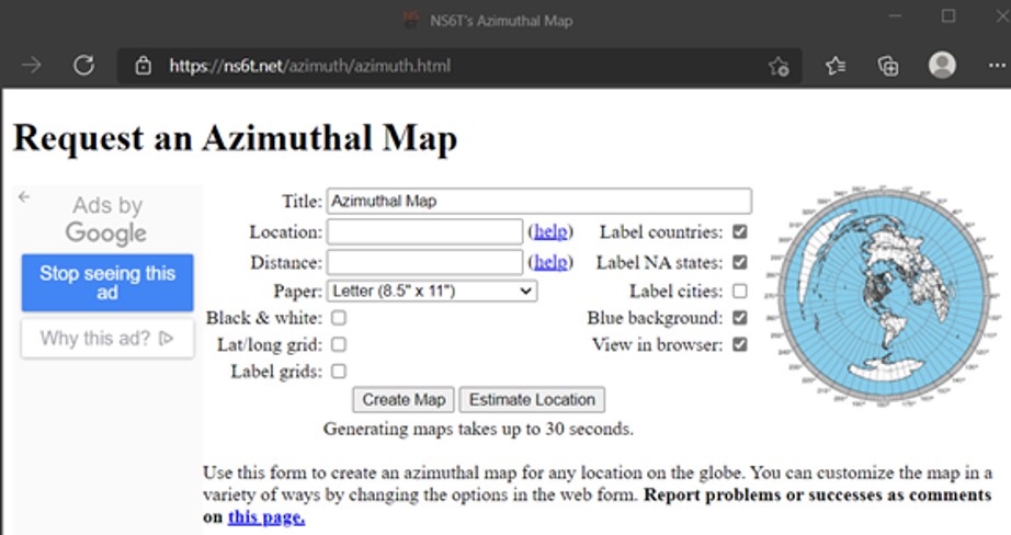
Azimuthal Maps
Request Azimuthal Map
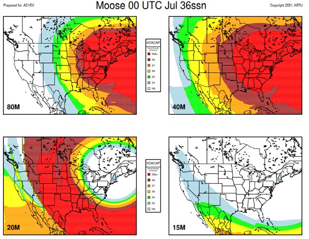
HFTA provides performance information for your antenna taking account of the terrain profile in a particular direction. Do you know what is out there in any direction? Standard Mercator maps show a representation of the world, but do not provide important information that is of use to Hams. There is a website that will create a map with your location at the center of it. It is free and all you need to know to use it is your grid square info. The more info you have the more accurate the map is.
You can put the map on your rotator controller to show where it is pointing. Some computer-based rotator control programs can also use the image.
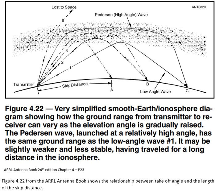
Take-off Angles
ARRL Take Off Angles
Why use HFTA
Use HFTA for planning an HF station scientifically. It can assist with determining the optimal antenna location and height. HFTA takes ground elevation data, frequency, and the height of the antenna to calculate the take-off angle in a specified direction. It is particularly useful for Hams interested in DX and contesting. Many of us use some type of propagation prediction tool to give us an idea of what bands may be open at a given time and to a specific location. Once the terrain profile and antenna information are configured the results can be used to provide a tool for propagation prediction that is custom tailored to your precise situation. This is very helpful when formulating strategies for contesting or hunting down rare DX. Terrain around your antenna up to 10,000 feet has a significant impact on your signal.
HFTA Models
Typical questions that HFTA can answer
How high should my antenna be?
Is it worth spending more money on a taller tower?
My mast is up 35 feet. Is it worth it to extend it to 45 feet?
Why can’t my antenna hear signals from ??
About to by a new house? Is the house location well suited for Ham Radio?
How does it work
1. Generate terrain profile data files. These are created using digital terrain data available from various online databases. There are a few additional programs that can be used to create these files and the HFTA instructions cover the required steps in detail.
2. Choose the type of antenna and the number and heights of antennas in a stack.
3. Select the type of antenna to be used.
4. Select an Elevation-Statistics file for your targeted receiving area. This file will include your station location (receiving area) and the area from which you will be receiving signals.
The software includes files with statistics that were computed for all the times over the 11-year solar cycle when each band was open. The Antenna Book’s data contains files for all regions of the USA to Europe (EU), the Far East (JA), South America (SA), South Asia (AS), Southern Africa (AF), and the South Pacific (OC), plus data files for a wide variety of other transmitting sites throughout the world. You choose the general area where your transmitter is located during initial installation of the HFTA program.
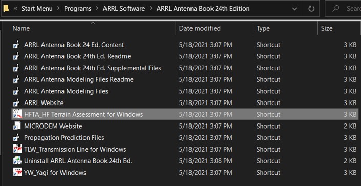
How to get HFTA
How to get HFTA
HFTA is included in the ARRL Antenna Book (currently 24th Edition). It is part of the package that includes the book when you get it for download from the ARRL. It was also included in a CD that came with the physical book. The e-book or Kindle is available from different sources. To be sure you get the software files associated with the book I suggest ordering it directly from the ARRL. Here is a link: http://www.arrl.org/shop/ARRL-Antenna-Book-eBook-Windows-Version/
K6TU.NET
K6TU.NET
The website https://www.k6tu.net/ is an excellent resource in combination with the HFTA software and offers many tools and resources beyond those that support HFTA.
Users need to register for free to use the tools and there is also a subscription service which offers more tools that go beyond the scope of HFTA available. To create HFTA Terrain Profiles, this website makes it very easy and offers very accurate data for stations located in the USA.
K6TU.NET provides a framework of simple to use forms to build propagation predictions or Terrain profile requests. Use the Resource menu at the top of the page to access guides, FAQs and background information. Use the Getting Started page to start with a tutorial which will guide you through the steps to create your first prediction.
Generating an accurate terrain profile
K6TU.NET now has the capability to generate a set of profile files for your location by simply filling in a form and submitting the request. Much like generating a Propagation Prediction, the site captures the information necessary to fulfill the request and then generates the results in the background. Once the results are available, an email is sent to you with a link to the results.
Generating a Terrain Profile Request is very simple and starts by selecting Terrain Profile from the New menu at the top of the page when you are logged in as a registered user. You do NOT need to be a subscriber to K6TU.NET to access this service – it is freely available to anyone with an activated account.
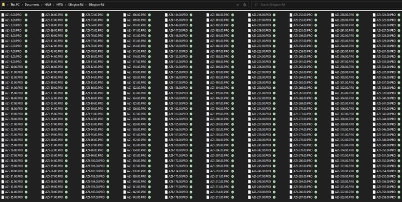
When the request is completed, the site creates a Terrain Profile Result which has a link to the ZIP file containing the terrain profile files (360 of them, one for each degree of azimuth) together with an explanation of the source of the terrain data for this profile.
Terrain Data
The screenshot above shows the 360 files for the terrain data for my QTH in Tewksbury, MA I have another folder with the terrain data for my NH QTH as well.
HFTASweep
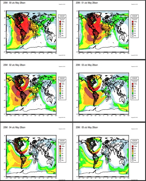
HFTASweep is a program “wrapper” for the ARRL HF Terrain Analysis program (HFTA). HFTASweep runs HFTA 90 times programmatically to model your HORIZONTAL polarized antenna over the actual terrain around your location. The program captures the results for each azimuth direction (4 different azimuth angles at a time) and at the end, builds a VOACAP type 13 antenna model as a file called antenna.13. You can upload type 13 antenna files to K6TU.NET and use them in the different prediction options by creating an Advanced Station Configuration from the New option under the Navigation menu. Once you have the type 13 antenna file you can use it to create custom tailored propagation forecasts. Here are a few examples:
HFTASweep
This is 20 meters in May. There is one chart per hour.
Custom Tailored Propagation Forecasts
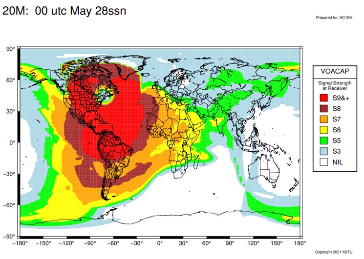
One Hour Forecast
Here is a close-up of one hour on 20 meters.
Contest Strategy
Contest Strategy
Another feature is to prepare multiple band reports to use for formulating contest strategy. Here is an example I created for my NH QTH for 13 Colonies back in July. There are very good instructions and examples on the K6TU web site. It is worth checking out.
How to use HFTA
Blank HFTA and Terrain Files
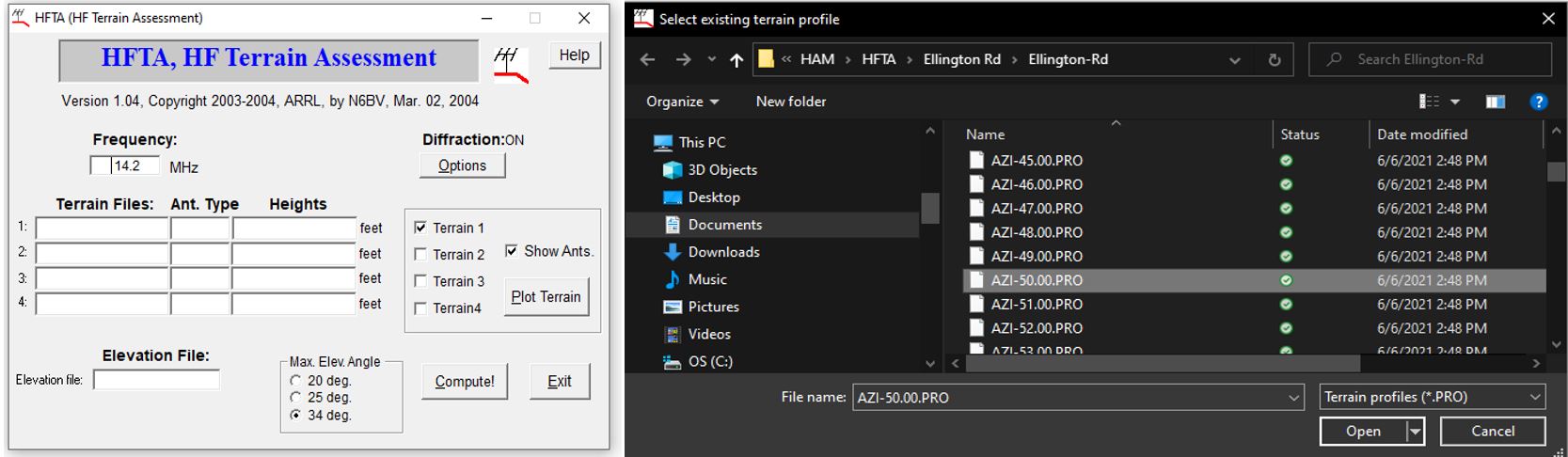
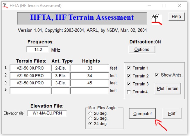
1. Launch the program
2. Select the terrain files you will use for this assessment by clicking in the box. In this example we will examine performance for 50 degrees, which is towards Europe. This Terrain File is for my MA QTH
HFTA Antenna Type
3. Click in the Ant. Type box to select the antenna type from a pull-down list. Enter the antenna height in the appropriate box. You can stack antennas up to 4 high!
4. Repeat for other antennas, locations, and heights you wish to compare. In this example I will add a 3 element yagi at 34 feet at my NH QTH (just select the Terrain Profile from that location) and a 3 element yagi at 45 feet from the NH QTH.
Add Elevation File
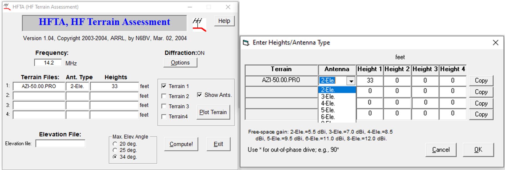
5. Enter the Frequency
6. Select an Elevation file. These are included with the HFTA software. They are the files derived from the 11-year statistical data mentioned above. This example is for Boston to Europe.
7. Check off the boxes for terrain for each antenna selected and HFTA will generate a profile for that compass heading.
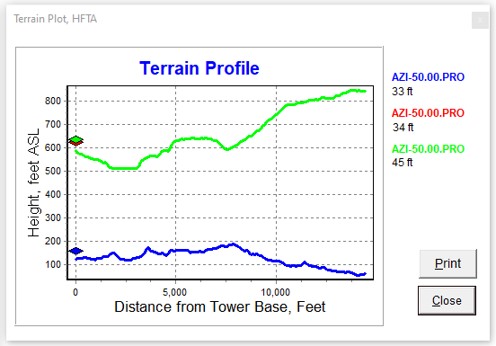
Terrain Profile
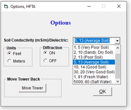
8. The Options button lets you configure units of measurement, Diffraction on/off, and Soil Conductivity (among other things). I have Diffraction turned on since I am around 3 miles from a ridge that is around 200 feet above my antenna. The chart makes it look like I am pointing into the hill, but it actually calculates out to be only 0.76 degrees up from my antenna. I believe my soil in NH is “Good Soil” but I selected Average Soil to create a conservative assessment.
OptionsReady to Compute
9. Click the Compute button to generate the chart.
My Results with HFTA
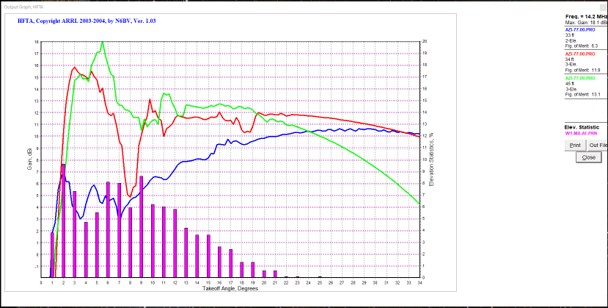
The Output Graph can be resized. Here are my results for the three antenna configurations pointing to Europe:
My Results
The Purple bars show the take-off angle plotted against the percent of time that signals arrive at that angle. This data is what is in the .prn files that you enter in the Elevation File field. Each antenna profile’s performance is represented by the colored line on the chart.
There are some very interesting things that show up on this chart:
1. The Spiderbeam at 33 feet has better performance at low angles than at 45 feet. Also, where the higher configuration is better, it is not a meaningful difference.
2. Both the Spiderbeam and the Hexbeam are adequate for coverage to Europe.
3. At this azimuth (50 deg) for some take-off angles the Spiderbeam has more than a 10 dBi advantage over the Hexbeam! This is before any radio or amp is added to the calculation.
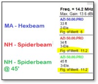
Figure of Merit
Figure of Merit
HFTA uses these elevation statistics, which indicate what percent of the time a signal arrives at a given elevation angle, and compares this info to your elevation plot, generating a relative performance rating called Figure of Merit, expressed in dB.
The software produces a “figure of merit” which is each antenna’s merit based on gain at takeoff angles where, statistically, the most prevalent signals can be expected. If you have great gain at takeoff angles where most of the time no signals are arriving, the FOM is low. When comparing different antenna configurations, the FOM can be used to identify which has an advantage. For the Spiderbeam used in my Europe example, the FOM is the same for 33 feet and 45 feet. The effort and risk to elevate the antenna does not appear worthwhile in this case.
Real World Example
Recently, I noticed a station from Kenya spotted on the cluster. I took a few minutes and was able to make a call successfully to 5Z4BU. I don’t often hear Kenya on the radio, so I ran an assessment using 77 degrees and the Africa Elevation file. Here are the results:
Real World Example
In this case the Spiderbeam at 45 feet would have an advantage, but the antenna at 33 feet was still capable of receiving signals from any likely take-off angles. The FOM for the 45-foot antenna was 1.2 higher than the 33-foot antenna. The Hexbeam in MA may have been able to make the call, but there was a pileup and the additional gain from the Spiderbeam really helped. I was able to make contact in 4 tries.
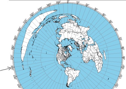
Australia and New Zealand
260 Degrees AZ Map
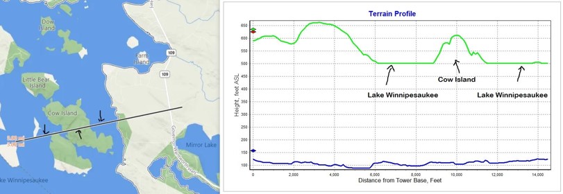
Here are two more examples to review. First, we’ll look at Australia and New Zealand. I’ll point my antenna at 260 degrees, which splits the difference between them.
Here is the terrain profile compared with the path covered on the map.
Lake Terrain ProfileAustralia and New Zealand
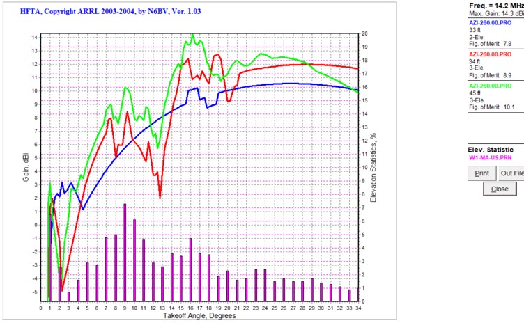
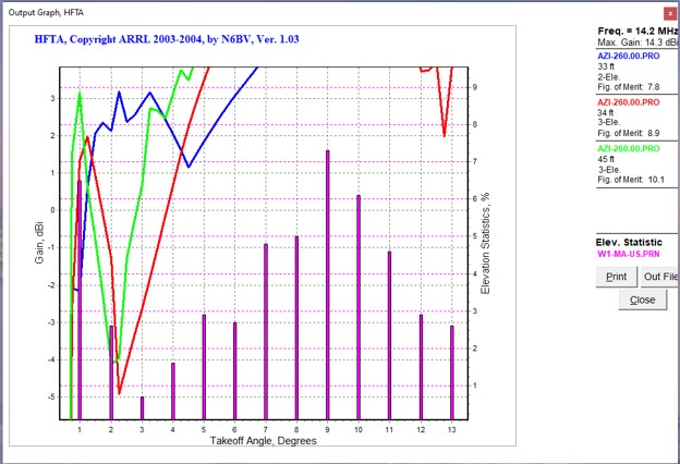
The chart above shows that although New Zealand is around 9,000 miles away, it is not difficult to make contacts there as there are many take off angles that can give successful results. You can select in the chart to capture a close-up of details.
Australia and NZ Close-up
The chart shows that the Spiderbeam at 45 feet will receive signals well at 1 degree and it looks like it will also at the 34-foot height. The Hexbeam will likely miss signals at 1 degree but should handle 2 degrees fine. New Zealand was one of my first Pacific DX QSOs and done with an OCFD and 100 watts.
Japan
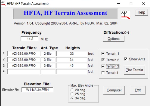
Next, we can check out Japan, which is at 335 degrees. We’ll review the steps again:
Japan
1.Select the Terrain files from each location for 335 degrees
2.Confirm Antenna type and heights are set properly.
3.Select the Elevation file
4.Click Compute!
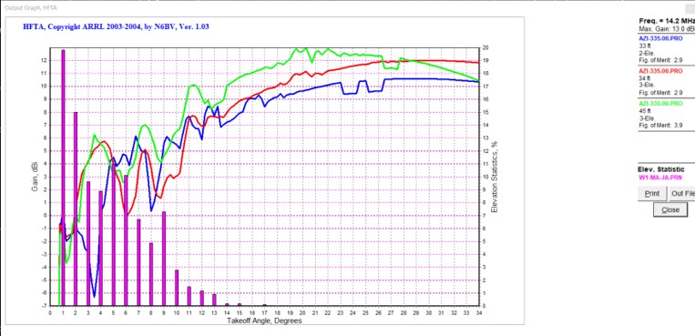
Japan Chart
This chart has lots of useful information. Unfortunately, it does not indicate that I will have a high probability of success contacting Japan. According to the chart, 20% of signals from Japan will come in around 1 degree and 15% at 2 degrees. Both antennas will fail at this angle. The Spiderbeam will have success from 3 degrees and higher. It is interesting to note that the Hexbeam will perform better at 6-degree take-off angle. Japan is only 6,700 miles away, but you can see it is way more difficult to reach than New Zealand.
Conclusion
This has been a simple introduction to HFTA. There are many documents and videos available that discuss the features of the program and strategies for using it.
How well an antenna “plays” depends on take-off angle to the target area, antenna height and local terrain
Lower is sometimes better.
More than one antenna per band will help your overall signal presence.
Design your antenna farm to cover all angles. If you can’t, choose what is important to you.
It is easier to make changes in the design stage of your antenna project. Time spent with this assessment tool can save big dollars and yield a better installation than trial and error.
The ARRL Antenna Book is a terrific resource. This presentation was based on only a tiny fraction of what the book covers. It makes a great gift, too!
We use cookies to ensure that we give you the best experience on our website. If you continue to use this site we will assume that you are happy with it.