Tag Archives: Station Building

Nashua Area Radio Society Field Day 2022

Nashua Area Radio Society Field Day 2022

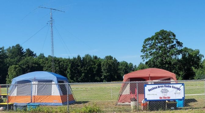
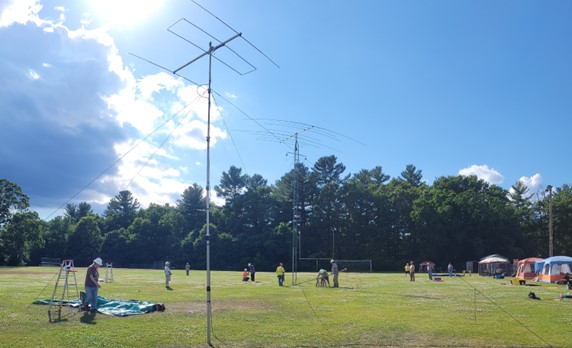
Field Day 2022 is over, creating great memories for all who joined us.  We have 47 names on our guest log, including members and visitors.  Add to that number our helpful volunteers, and over 70 people participated in Field Day with us. This year we returned to Hudson Memorial School, the site of some of our most ambitious past Field Days.  Our current effort was more modest, we would be class 3A, with four radios and antennas to cover 6, 10, 15, 20, 40, and 80-meter bands.  Our primary tower was 40 feet tall and held a tri-band Yagi and two dipoles, one each for 40 meters and 80 meters.  For 6 meters, we had a loop-fed array on a push-up mast.  All of our radios were configured to support all modes, SSB, CW, and Digital.  Each station incorporated a laptop PC to run our logging application and support digital modes.

Planning

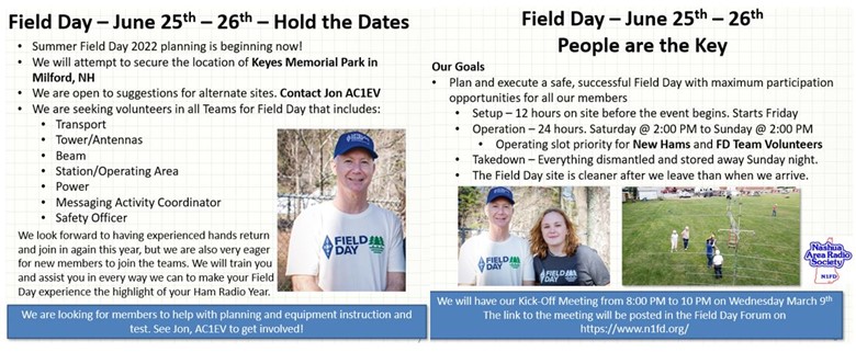
Our Kick-Off Meeting for Field Day was on March 9.  There is lots of planning and training to do before the day of the event.  Many of our volunteers have participated in Field Day with the club in past years, but this year some of them would become the leaders of their teams for the first time, myself included.  Fred, AB1OC, and Anita, AB1QB, would represent the ARRL in their new roles during Field Day and leave their past roles in NARS Field Days for other members to fill.  I volunteered to lead the effort this year, and both Fred and Anita generously gave their time and advice to our team to assist with planning and training for the event.

Hold The Dates
Hold The Dates

My first efforts went towards finding a group of volunteers who would commit to the project and to securing a venue for the event. In recent years we had successfully held Field Day at Keyes Memorial Park in Milford, NH, but this year it was booked for Field Day.  We also had great success with Field Day at the Hudson Memorial School in Hudson, NH so I inquired with them about returning to their site.  The school is a friend of NARS, we have done many activities with them, including an ARISS contact, so they made it easy for us to engage and obtain approval to use their field. Special thanks to Principal Keith Bowen for making this painless.

The Field Day 2022 Teams

We had 20 members volunteer to support our Field Day effort from planning in the beginning to putting the last bit of gear back into storage on Sunday night after the event.  Other members assisted as they could during planning or the during the event itself.  While NARS owns a lot of the gear we used for Field Day, we do not own any radios or peripherals.  We are very fortunate to have members who generously lent their radios and other gear to the cause. In our first few planning meetings, we took stock of our team’s skills, experience, and preferences and sorted ourselves into functional teams.  We were fortunate that each team leader had the basic skills and experience needed to assume their role.  We would arrange training where needed and documentation from past field days to take advantage of hard-won knowledge from past efforts.  The teams broke down as follows:
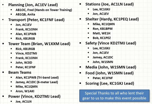
Team Members
Team Members

Transport Team

NARS has a storage trailer where we keep all of our gear that does not require a climate-controlled environment. Much of this gear is only used for our Field Day activities. On Field Day, our day begins here, the Transport Team gathers, and the other Team Leads make sure that all of the material they will need at our Field Day site is loaded onto the trucks.  We are fortunate that we have many members with pickup trucks, and we also have a number of trailers available.  We spent around 2 hours at the trailer on Friday morning loading the trucks with our gear.  This year our Field Day site was only a 15-minute drive from our store. Murphy loves Field Day, so we did make a return trip to the trailer to pick up additional material before the day was done.

Transport Team
Transport Team

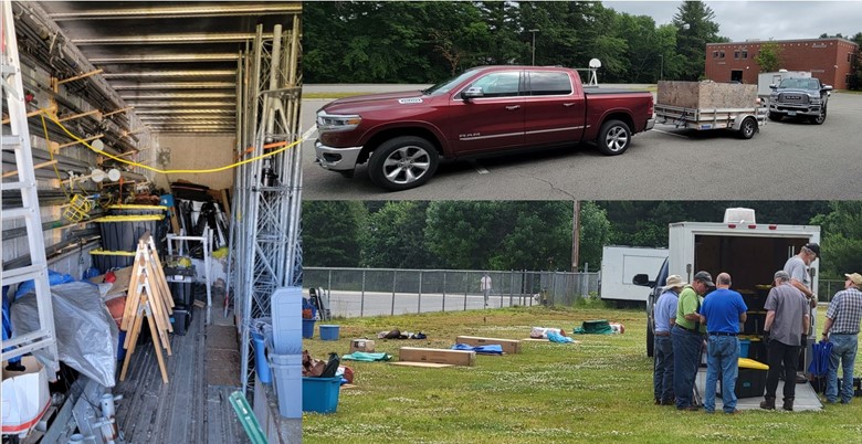
Once we arrived at Hudson Memorial School, we were able to unload and stage our equipment on the field prior to beginning setup.  Most of the team members from the other functional teams were there to assist, and the job was done very quickly.

Shelter Team

On March 15th, 7 members of the Nashua Area Radio Society met at BOB, our storage location for club gear, to do an initial gear test and evaluation to begin our hands-on preparation for Field Day.

Shelter Team
Shelter Team

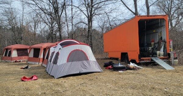
This gave the Shelter team a chance to set up all of the tents we would use and confirm that everything was in order and identify any gaps.  We also inventoried tower and antenna components to prepare for future training.  A more detailed article about this is here:

Gear Test and Evaluation for Field Day 2022 – Nashua Area Radio Society (n1fd.org)

Tower Team

As we met each week and worked out our upcoming tasks and responsibilities, we also uncovered areas where we needed to fill gaps in knowledge and skills.

Towers
Towers

One such area was in the Tower team.  Everyone on the Tower team had experience from past Field Days, but all had worked under a team leader who was no longer going to be active with us in our efforts this year.  Fred, AB1OC, led the team in the past and offered to provide us with hands-on training for erecting the tower and antennas in May.  This would give us the perfect opportunity to actually raise the tower, assemble the antennas and confirm that we had all of the assembly steps properly documented and that we had all of the required parts and materials available as well.  We met at BOB on May 11 and had a full-scale dress rehearsal for the Tower and Beam teams. You can read about this event in this article:

Hands-On Tower and Beam Antenna Training for 2022 Field Day (n1fd.org)

Beam Team

The Beam Team is responsible for assembling the antenna and making sure it is properly in tune for each band prior to raising the tower.  Our antenna is from 2014 and has been assembled and disassembled many times over the years.  There are many small parts, so the team performs the assembly on sawhorses placed on tarps. This allows for easy retrieval of any parts that may drop during assembly.  When the beam is completed, they sweep it with an SWR meter to confirm it is in proper tune. This beam antenna covers 10, 15, and 20 meters.

Beam Team
Beam Team

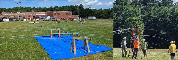
Once tested, the assembled antenna is carefully mated to the mast on the tower and the coax is attached.

Station Team

The Station Team also had a complex task to complete.  As a 3A Field Day station we would have 4 radios in operation.  We were going to have each radio setup in a separate tent with a laptop computer for logging and digital modes, and a Winkeyer and paddles for CW. Each radio is limited to specific bands and the coax to the antennas would be routed through band pass filters and/or a multiplexer and antenna switch on the way to the relevant antennas.  Figuring this out on the day of the event was not an option, so we planned on creating a full-scale test setup of the configuration prior to the event. I had experience with this area and had been a station master in a past 14A Field Day with NARS so could help out.  Joe, AC1LN volunteered to lead the team and Lee, KC1GKJ joined in to assist.  We were able to consult with documentation created in past years and that formed a good base of knowledge for us. We arranged with Fred, AB1OC to have a focused training at his QTH for some of the details of setting up the IC-7300 radios, N1MM+ logger and WSJT-X software along with the Winkeyers and paddles.  The goal of that training was to properly configure one radio and laptop and use that setup as a reference to roll out to the other radios. Shortly before the training, I caught Covid-19 and could not attend. Joe and Lee worked with Fred and accomplished the initial goal of setting up the first radio.

Joe volunteered to do the trial setup at his QTH and was able to set up an area in his basement that we could work in.  We were able to gather the gear we would borrow for the event and set it all up in the test lab at Joe’s. Thanks to Fred AB1OC, Lee KC1GKJ, Jamey AC1DC, Jack WM0G, Dave K1DLM, and Jon AC1EV for generously loaning their gear to the cause.

Station Team
Station Team

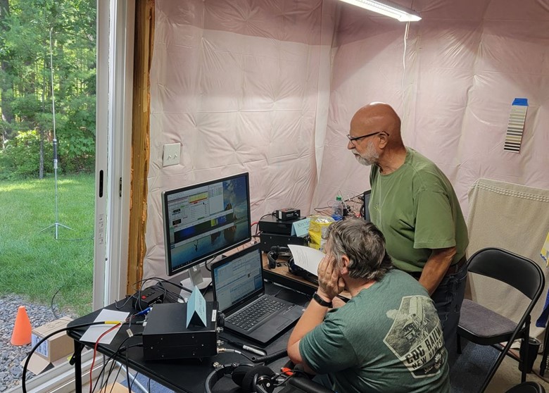
Joe, Lee, and I took multiple passes at completing the full setup of the IC-7300s along with the laptops and software to get everything configured properly. There are levels and levels of settings to manage, and we were able to get them ready in advance, so set up at Field Day was just a matter of assembling all of the labeled components. We used the Super Antenna MP1, seen in the background for testing on 20 meters, and Jerry AE7KI, an old friend from Tennessee, gave us an excellent report.

Media, Publicity, and Food

While all of the above activities were underway, John W1SMN was working behind the scenes to promote our Field Day activity.  He worked to contact various government officials, news media, and others to invite them to join us on Field Day.  He also worked with local businesses to obtain support from them for our efforts.  Here are the major donors to our event.

Sponsors on Food Tent
Sponsors of Food Tent

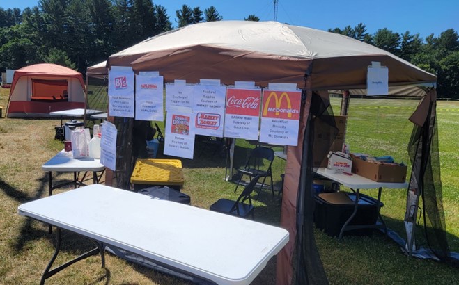
Nashua Area Radio Society is grateful for the support from these businesses, and we presented a certificate of appreciation to each of them to say thank you for supporting us.

Certificate of Appreciation

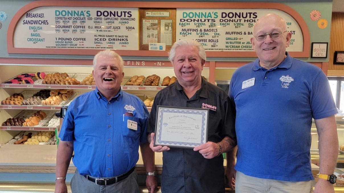
Here John W1SMN and I present Bill Wilson, owner of Donna’s Donuts in Tewksbury, MA, with a certificate of appreciation from the club.

Ready to begin

HMS Layout
HMS Layout

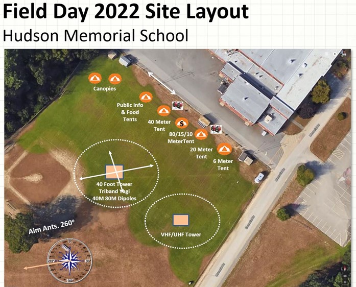
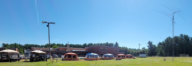
Here is a diagram of our proposed setup at Hudson Memorial School in Hudson, NH.  We have done much larger Field Days here in the past, even as large as 14A, so there is plenty of room for our setup this year.  As you can see from the following pictures, we were able to make the diagram above into a reality.

Tents and Towers
Tents and Towers

Operating

This year NARS is operating in class 3A. This means we are a club and have 4 radios. In addition to our 4 radios that can contribute to our QSO count, we also had another radio setup as a GOTA station.  GOTA stands for Get On The Air.  This station allowed our visitors to make contacts and join in the fun. No license is required as there is a Control Operator present under whose authority the visitor can operate.

Youngsters at GOTA
Youngsters at GOTA

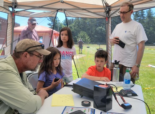
Some of our members came with their children and they were very enthusiastic about making contacts.  Day or night, the GOTA station had lots of use.  Each GOTA operator received a certificate to commemorate their participation.

Day and Night GOTA
Day and Night GOTA

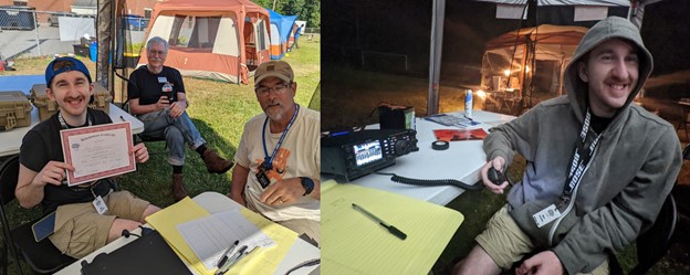
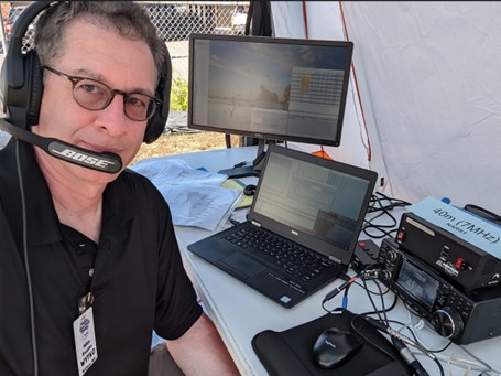
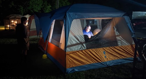
Club members also operated day and night. Each station was configured to cover all modes, so the operator could choose from Phone, CW, or Digital modes.  To maintain social distancing in this time of COVID-19, we only had one radio per tent.  Here is how each tent was setup. We had an IC-7300, power supply, Winkeyer, paddles, laptop, mouse, and external monitor.  The laptop was connected to the IC-7300 and was running N1MM+ and WSJT-X software.  All Laptops were networked together including a 5th laptop in our information tent, so we could track our cumulative QSO score in real time.

40 Meter Operating Position

This being Summer Field Day it was hot during the day. Propagation was good at night, so we had many members operating at that time. Each operating station included a fan and light so we could see what we were doing and stay cool.

Night Operator
Night Operator

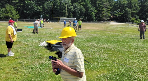
Field Day operations last for 24 hours and after that it is time to break down the setup and return everything to its place.  We learned in past years that effort spent during this time to stay organized pays extra dividends next year when we do it all over again.  Our members really put in extra effort for this, after a few long hot days and even with everyone tired from Friday and Saturday’s work, had enough energy and effort to complete the task.  From the end of operations at 2:00 PM on Sunday to the last items stored at BOB and the 6-meter antenna and mast returned to Hollis only took around 4 ½ hours.  There are a dozen people in this picture helping with breakdown and others out of view.

Breakdown on Sunday
Breakdown on Sunday

Field Day 2022 – How Did We Do?

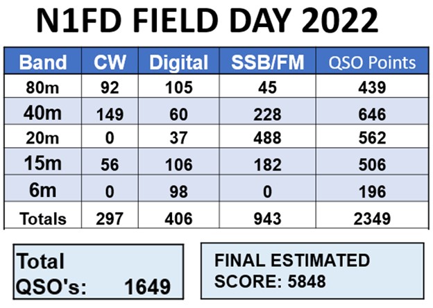
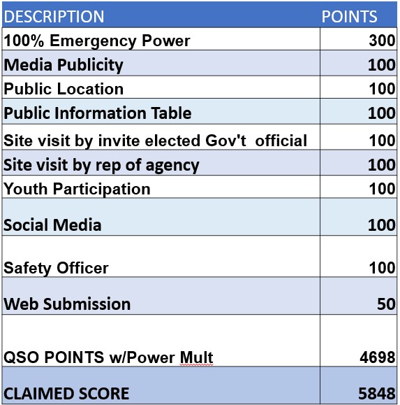
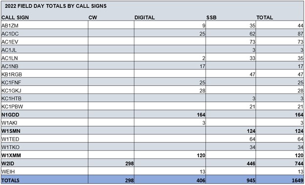
Lots of people had loads of fun! In addition to operating the radios we also learned from every aspect of the event.  Field Day is a complex endeavor; we began planning in March and acquired new skills as we progressed towards the day of the event.  We worked together and depended on each other. We shared our skills and now those skills are an asset to the club.  This year we took training on things we didn’t know and next year we may give training in those same areas to others who follow us. Experienced Hams know that Field Day isn’t a contest, but we do keep score! Here are some of our stats.


QSO Score
QSO Score
Bonus Scores
Bonus Scores
Totals by Call Signs

Summer Field Day is the highlight of the year for many hams.  It is a big part of the history of the  Nashua Area Radio Society. It is also a lot of work. When I first joined NARS as an inexperienced ham, I witnessed a very ambitious FD effort with 3 40’ towers, a 60’ tower, a 40 meter V Beam, VHF, and satellite antennas as well.  I was very impressed and decided that I wanted to participate in the event the next year.  The following year, the club had a similar effort, I think it was 14A and our score reflected our size.  Since then, with Covid-19 restrictions and changes in club membership we scaled back our operation. We are fortunate that many of the volunteers who participated this year had experience in past years and were able to assume leadership roles. Our new members are now experienced too, and the club will benefit from the expanded skill sets of its members. We all had fun and working together has given many of us the basis for lasting friendships. We will take advantage of this year’s event to learn from it and apply those lessons to next years Field Day.  That’s it for now, 73 and best wishes from

Jon AC1EV

Control Your Rig Remotely With This USB-Controlled Power Station

Introduction

Remote station operation has become more popular now that several rig manufacturers offer accessories to enable the radio amateur to do so. However, there is usually a large expense associated with acquiring these accessories. For some, it may not be cost-effective to own them for occasional use. In this article, we describe a solution for remote operation from another room of your home, your yard, or while on travel. It is also convenient for controlling on/off functions in the shack with the click of the mouse. The solution revolves around a Velleman relay card that can control a number of relays from a computer desktop.

The Power Station

This article describes a USB-controlled AC power strip, Figure 1, that was built around the Velleman K8090 8-Channel Relay Board in kit-form [1]. Varistors were added to the board as a recommended option [2]. The board can also be purchased fully assembled [3].

Figure 1. USB Controlled Power Strip. Each 15A duplex outlet is under USB control. There are just enough contacts on the barrier strip for 8 relays, neutrals, and grounds.

The PC communicates to the board via USB. A free, desktop, graphical user interface (GUI) is provided by Velleman for use as test software, or you may opt to purchase an application such as N-Button Lite [4].

Some type of rig interface is required to control your rig and audio from a PC. You may use the interface in your rig if it has one, or buy or build one of your own.

In order to log onto your computer, see your desktop remotely and hear rig audio, some kind of conferencing software is required. I use TeamViewer [5] to see my desktop and hear computer audio remotely.

Cautionary Notes

You will be dealing with AC line voltage in this project. Keep the clear polycarbonate cover on the enclosure while AC power is applied. Since the Velleman card operates on 12 VDC and control is over USB, all testing can be completed prior to plugging the AC line cord into the wall socket.

The FCC requires some means to disable the transmitter within 3-minutes if something goes wrong during remote operation. Velleman makes a WMT1206 Universal Timer Module with USB Interface [6] that should prove useful for this application. Its relay can handle 8A of AC. There are also similar USB timer modules available on eBay. It’s also a good idea to have the ability to reboot your computer remotely. The exact details of how to implement this FCC requirement are left to the reader but there are plenty of suggestions to be found online.

Kit Construction

An experienced kit builder can assemble and test the board in an afternoon. The added varistors are specified at 125J, 300VAC, 385VDC, and 4500A clamping peak current [7]. If these are not readily available, there are equivalents. A suggestion was made to thicken the circuit board traces that must handle the 16A relay current with additional solder. I didn’t care for this approach and opted to solder bus wire onto these traces, instead. You might find it ludicrous to solder #14 AWG buss wire onto the board, so your other option is to derate the relay capabilities to what the conductors can safely handle since the PCB traces have not been rated. For example, the ampacity of #20 AWG buss wire is at least 5A (11A at 75°C) [8], and that will be good for 575W. None of the circuits that I run from this PCB require anywhere near 575W.  Take care not to damage the PCB traces while soldering. Excessive heat will lift the PCB traces.

Housing, Connectors, and AC Outlets

There are 8 duplex outlets in this project – each one under separate relay control. Each outlet has been wired with #14 AWG. Each relay is rated at 16A, resistive load (see the previous section for derating). The duplex outlets have been spaced far apart so that a variety of line cords and wall adapters will fit without interference. The control board is housed in a Bud Industries PN-1340-C polycarbonate enclosure [9] with a clear cover (not affixed), Figure 2. The clear cover provides visibility for the status lights on the PCB. Bud Industries also manufactures an internal aluminum panel, PNX-91440 [10], upon which the PCB and barrier strip have been mounted. Take care in locating connectors on the housing or the PCB will not fit. The PCB is fastened to the aluminum panel with 4-40 hex standoffs. The Bud Industries enclosure is fitted with 1/2-inch male terminal adapters [11] at either end. DC power for the relays enters the enclosure at the top left through a 2.1mm panel mount connector [12]. The relay power required is 12VDC at 400mA. A 12 VDC wall adapter with a 2.1mm plug can provide this voltage. AC power enters the housing through a cable gland at the lower left. Switchcraft makes the USB connector at the lower right. It converts USB A inside the enclosure to USB B on the outside. The connector was purchased from Newark [13]. The short USB jumper patch cord was purchased on Amazon [14]. A step drill [15] is the most effective way to bore the large holes in a polycarbonate or ABS case without cracking it.

Remote Control

Figure 2. Interior View of Control Board Enclosure. Eight 16A relays are visible. There’s not much space to spare. Take care in wiring the AC connections and in locating the connectors on the housing or the PCB will not fit.

Software Apps

The test software that is supplied by Velleman for the circuit card is adequate, or N-Button Lite [16] may be purchased Figure 3. A screenshot of the lower right corner of the monitor shows the buttons for N-Button Lite. The green buttons indicate that four of the eight relays are active. If you purchase the Bud enclosure with a clear polycarbonate cover as I did, you will be able to see all eight red indicator lights on the Velleman board, one for each relay. They will light when a relay becomes active.

Remote Control

Figure 3. Screenshot of PC desktop. N-Button Lite controls each of 8 relays.

References

References
[1] https://www.jameco.com/z/K8090-Velleman-8-Channel-USB-Relay-Card-Kit_2123952.html
[2] https://www.velleman.eu/products/spareparts/?code=vdr300
[3] https://www.amazon.com/Velleman-VM8090-8-Channel-Relay-Card/dp/B00CPCQ88Y
[4] https://www.serialporttool.com/GK/n-button-lite/
[5] https://www.teamviewer.com/en-us/?utm_source=google&utm_medium=cpc&utm_campaign=us|b|pr|19|jul|Brand-TeamViewer-Exact|free|t0|0|dl|g&utm_content=TeamViewer_Exact&utm_term=teamviewer&gclid=Cj0KCQjw5ZSWBhCVARIsALERCvzZflNoCfAiFgi9STEIDiJkCtRuazuukru
[6] https://whadda.com/product/universal-timer-module-with-usb-interface-wmt206/
[7] Velleman, op. cit. https://www.velleman.eu/products/spareparts/?code=vdr300
[8] https://en.wikipedia.org/wiki/American_wire_gauge
[9] https://www.budind.com/product/nema-ip-rated-boxes/pn-series-nema-box/ip65-nema-4x-box-with-clear-cover-pn-1340-c/ – group=series-products&external_dimension
[10] https://www.budind.com/accessories/aluminum-internal-panel-pnx-91440/
[11]https://www.homedepot.com/p/1-2-in-Male-Terminal-Adapter-R5140103/202043509
[12] https://www.amazon.com/2-1mm-DC-Power-Jack-Chassis/dp/B073PKZPQ7
[13] https://www.newark.com/switchcraft-conxall/ehusbbabxpkg/usb-adapter-type-b-rcpt-a-rcpt/dp/08N9043?gclid=Cj0KCQjw5ZSWBhCVARIsALERCvycmWj-i38ykHaPrlbG8Eb-uxCyxcpZzdNWmZ0r7Z2iV9zgd7CpVKAaAh5KEALw_wcB&mckv=_dc|pcrid||plid||kword||match||slid||product|
[14] https://www.amazon.com/inch-USB-2-0-Male-Cable/dp/B079ZP65SN?th=1
[15] https://www.homedepot.com/s/step%2520drill?NCNI-5
[16] Relay Pros, op. cit. https://www.serialporttool.com/GK/n-button-lite/

Highly Efficient L-Matching Networks for End-Fed Half-Wave Antennas

Introduction

End-fed half-wave (EFHW) antennas provide a convenient way to move the coaxial feedpoint for a half-wave antenna from the center to one end. There are three types of antenna feeds in popular use: 1) transformer feed, 2) L-matching network feed, and 3) Zepp.

The transformer feed variety may be broadband and, depending upon its construction may be useful over the entire HF spectrum. On the other hand, an L-matching network will only work on a single band. There are distinct advantages and disadvantages for each type of feed. This article will discuss the L-matching network feed in detail. The subject of ferrite transformer feeds will be discussed in detail in another article. The subject of Zepp antenna feeds is discussed in great detail in many antenna books [1]. One may think of a Zepp antenna as a folded full-wave antenna usually fed 0.25 wavelength from one end. When one unfolds the antenna, we have an off-center-fed (OCF), full-wave antenna. Depending upon the feed section, a single or double Zepp antenna may be designed to have the advantage of fundamental and harmonic operation.

If fed with an L-matching network, an EFHW antenna may possess an efficiency that exceeds 95%. Here are some things to consider when designing and using this antenna.

First, the load impedance at the end of the half-wave wire must be determined by iteration or through electromagnetic analysis. The load impedance will dictate the values of the L-matching network components. Parameters that have the greatest effect on load impedance are antenna height above terrain, physical properties of the antenna conductor, ground properties, and immediate surroundings.

If we may digress for a moment, the radiation resistance of a center-fed half-wave dipole is well understood, and it varies with wavelengths above the terrain, as shown in Figure 1. For example, if we were to elevate a 40m dipole to 33′ (10m) above the terrain, we would expect a radiation resistance of about 80 ohms at the bottom of the band. This has been verified by modeling the antenna in EZNEC [2] (81.3 ohms) and by field measurement (78.8 ohms) [3]. One would expect the end resistance of a half-wave wire to vary in the same way, although at a vastly different impedance level.

Figure 1. Radiation Resistance of a Dipole Above a Perfectly Conducting Plane. Radiation resistance values for horizontal and vertical dipoles are shown as a function of wavelength above a perfectly conducting plane. The dotted line shows how the radiation resistance of a horizontal dipole departs from the graph when the dipole is close to real ground. It is expected that the end resistance of our EFHW antenna will follow similar variations as a function of wavelength above ground, although at very different impedance levels.

This article will present test results measured at 5 frequencies in 5 bands to demonstrate how end resistances vary at a fixed height above terrain. We allow the number of wavelengths above ground to vary as a function of frequency while holding the antenna height constant. There is not enough test data to draw any conclusions other than to say that the end resistance appears to vary as a function of wavelength above the terrain. It is hoped that the measurement program will be completed as future work.

Second, if the antenna is fed close to where the radio operator will sit, as may be the case for portable operation, the electromagnetic fields at the end of the antenna may rapidly exceed those recommended by the FCC for controlled and uncontrolled environments. For this reason, it is recommended that both ends of the antenna be elevated, with the possible exception of QRP operation.

Third, any end-fed half-wave antenna will require a counterpoise. Sometimes, the counterpoise is provided by the coax that feeds the L-matching network, in which case the feedline will definitely carry common mode currents that will tend to spoil the antenna pattern of the half-wave wire. Since the coax that feeds the L-matching network steals current from the half-wave wire, it reduces the main-beam efficiency. This problem can be remedied by placing a common mode choke in the feedline at a distance of 0.05 wavelength [4] from the L-matching network. Since the common mode currents are on the outside of the shield, the value of 0.05 wavelength is measured in air, not in coax. Any effect due to the outer jacketing will be small. Be advised, however, that the 0.05 wavelength value is not cast in concrete. It is a starting point. To be absolutely sure, the currents on the transmission line shield, counterpoise, and antenna wire should be measured with an RF current probe. One such probe is the MFJ-854 [5]. As will be shown by electromagnetic analysis with EZNEC in another article, there will always be some RF currents where we don’t want them to be.

While a portion of the coaxial feedline may serve as a counterpoise, the alternative is to co-locate the common mode choke with the L-matching network so that a separate counterpoise wire can be connected to the L-matching network ground. In any event, the counterpoise conductor should be perpendicular to the half-wave radiator, regardless of whether it is horizontal or vertical, to minimize the interaction of counterpoise fields with the main antenna beam.

Methodology

A lowpass L-matching topology is employed as shown in Figure 2 – a series inductor followed by a shunt, open-ended coaxial capacitor consisting of RG-316/U. (RG-316/U coax has a capacitance of 29 pf/ft.) It is widely known that if the shunt-matching element is in parallel with the load, the transformation will be from a higher load impedance to a lower source impedance [6]. This configuration is very easy to tune. However, this configuration will not bleed static charge from the antenna wire. While a series capacitor followed by a shunt inductor in parallel with the load will provide a similar transformation and static protection, this topology is more expensive to realize and more difficult to tune. We bring this point to your attention because static protection is often omitted from antenna installations.

The matching schematic below, and tutorial from Professor Stephen Long, Emeritus, ECE, UCSB, may be found online [7].Figure 2. Lowpass Topology. The inductor may be air-wound or toroidally-wound, while the capacitor consists of an open-ended piece of RG-316/U. While the capacitor appears to be grounded at the bottom of the capacitor, for this implementation, the ground connection is soldered to the shield-end closest to the inductor. Rs is the 50-ohm source impedance, real, while Rp is the antenna end impedance, real.

An online calculator that performs all of the calculations for a variety of L-Matching Network topologies may be found on John Wetherell’s website [8]. While online calculators are great, the reader is encouraged to perform at least one calculation if only to verify that the calculator yields the same result as theirs.

A quick way to arrive at the values for the matching elements is to estimate the impedance transformation ratio required. For example, if we needed to transform from a 50-ohm source to a 4800-ohm load impedance, the impedance transformation ratio would be 1:96. From that, we obtain the unloaded Q and the reactance values required.The unloaded Q = 9.75, and the reactance required for the inductor at the design frequency would be 488 ohms. The reactance required for the capacitor would be 492 ohms. If we were designing for 80m, we would calculate the inductance and capacitance from the reactance formulas at, for example, 3.6 MHz.

The series inductance would be 21.6 μH, and the shunt capacitance would be 89.8 pf. Then, we would build the network with a coaxial capacitor that had been cut too long and load the network with a 4800-ohm non-inductive resistor. An antenna analyzer would be connected to the network as the source, and the coaxial capacitor would be pruned a tiny bit at a time (it is easy to overshoot the mark) until the reactance at the design frequency had been canceled. If the antenna analyzer could be connected to a PC, tuning might be performed in real-time. A convenient display to use would be the Smith Chart view.

Two tables of component values at frequencies in commonly used ham bands are provided in Table 1 for CW and Table 2 for SSB. The tables are parametric and provide component values for a variety of EFHW antenna end resistances from 2000 to 4800 ohms.

A good starting value for any design is 3200 ohms, and in most cases, it will deliver satisfactory results. One need not rely upon the design frequencies in the tables. You now have all tools that you need to design networks for any frequency and any load impedance!Table 1. CW Band Segment Component Values as a Function of End-Fed Half-Wave Antenna End Resistance.Table 2. SSB Band Segment Component Values as a Function of End-Fed Half-Wave Antenna End Resistance.

Determining Component Values

Access to an Inductance-Capacitance-Resistance (LCR) meter is highly desirable to ensure that the L-matching networks are being built to the design values. Fortunately, these instruments have become inexpensive and accurate, and they are quite useful for identifying unknown component values.

Implementation

A 30m L-matching network test article that employs an air-wound inductor is depicted in Figure 3. The sketch in Figure 4 shows the network interconnects in greater detail. The final iterated load impedance was 3024 ohms, the inductance value was 6.16 μH, and the final capacitance value was 41.7 pf. The resulting VSWR was 1.04:1 at 10.133 MHz. The air inductor was been wound on a scrap length of ½” PVC conduit. The OD of this conduit is 0.840” (21.34mm). The inductance wound for this test article consists of 22 tightly-wound turns of #20 AWG enameled magnet wire, but #18 AWG is highly recommended for the final L-matching network. Hot glue was used to hold the turns together during tests, but non-corrosive silicone is recommended once the inductance has been finalized. You can use an online calculator to estimate the number of turns required for the air-wound inductor of a specific diameter and length [9], but please use an LCR meter for precision. The capacitor consists of an open-ended piece of RG-316/U coax that was chosen for its maximum voltage rating of 1,200 volts and 29 pf/foot capacitance. The approximate length of our coaxial capacitor is 17 inches. In a separate article, we will discuss voltage requirements for transmission lines when subjected to elevated VSWR.

Figure 3. Lowpass L-Matching Network Topology for 30m Test Article. The air-wound inductor consisting of #20 AWG enameled magnet wire is connected from the center conductor of the SO-239 UHF connector straight through to the antenna terminal. Hot glue holds the turns in place. The coaxial capacitor center conductor is connected directly to the antenna terminal. The other end of the coaxial capacitor remains open-circuited. The photo shows a short piece of clear shrink tubing that protects the open end of the coax (see text). A ground connection to the coaxial capacitor shield is soldered near the antenna terminal end of the coax with a piece of buss wire (see Figure 3). The other end of the bus wire is grounded to the flange of the SO-239 UHF connector with a solder lug. The housing is a Bud Industries PN-1320.

Figure 4. Lowpass L-Matching Network with Air-Wound Inductor Interconnects. The sketch shows where an optional, separate counterpoise may be connected if the coax is not used as the counterpoise. It also shows where the ground connection is soldered onto the coaxial capacitor shield. The dotted lines show where to connect the test load resistor to the network.


Figure 5 shows the configuration for a 15m L-matching network test article. The magnet wire gauge used is #18 AWG because the inductor will fit the housing. Hot glue is used to keep the turns in place. The final inductance value is 2.91 μH, and the coaxial capacitor value is 20.7 pf. The test frequency is 21.09 MHz, while the end resistance is 3042 ohms. The uninsulated open circuited coax is visible. The braid and jacket must be pruned back and insulated to prevent RF arcing. A 1 pf capacitor is soldered in parallel with a coaxial capacitor to correct the capacitance. This capacitor combination was replaced with a longer piece of coax for the final configuration.


Figure 5. A 15m L-Matching Network Test Article. A 1 pf capacitor  (visible in the white circle) is soldered in parallel with the coaxial capacitor to tune the network without changing the coax. The coaxial capacitor will have to be changed before transmitting because the capacitor is not rated for high RF voltage.


In order to prevent the coaxial capacitor from arcing from its center conductor to the shield near its open end, it is a good idea to snip back the coax shield a tiny bit near the open end. This has to be done while the coaxial capacitor is being tuned to its final value, however. Once one arrives at the final value, the end of the coax may be covered with a short length of shrink tubing to protect it. When tuning these networks for the higher bands, namely 20, 17, 12, and 10 meters, it may be beneficial to complete the tuning with the coax coiled in its final configuration. The pruning procedure can be somewhat fussy, and altering the capacitor configuration at the very end can lead to disappointing results.

From the network configuration, one can see that there is always access to the inductor and capacitor for measurement. It is a good idea to record the as-built values of the network once it has been tuned into the test load. Many times it will be found that the as-built values will not be exactly the same as the design values. The reason is usually the inter-turn capacitance of the air-wound coil. It’s alright as long as there is a good match into the test load resistor. We will explore the inter-turn capacitance in a separate article.

One final note on construction: The inductors for the 160, 80, 60, and 40m bands will require a large number of turns. If air-wound, they may be too long to fit within your enclosure. One solution has been to build the network in a bigger enclosure. That will preserve the low-loss properties of the L-matching network. There will be a separate article that describes the construction of a 600W L-matching network with an air inductor for 40m. For portable use, however, compactness may be a virtue, and you may wish to wind the inductors in some other way at the expense of some RF efficiency. For such cases, consider the use of small ferrite or iron cores. You will want to choose a core type for the frequency range of interest, most likely #2 (red) iron material [10] or #61 ferrite material [11]. The permeability of iron is much lower than it is for ferrite. More turns will be required on an iron core. You may also want to choose a core size that is large enough for several turns. If the core doesn’t have enough turns, it will be difficult to fine-tune the inductance. If there are too few turns, even a small adjustment will dramatically affect the inductance, and the required value will not be obtained. A 40m L-matching network that employs a toroidal inductor is depicted in Figure 6. The sketch in Figure 7 shows the network interconnects in greater detail. An FT114-61 ferrite core has been used for 40m. Eleven turns of #18 AWG magnet wire were required to obtain 10.4 μH. The coaxial capacitor consists of approximately 19” of RG-316/U. The inductance of the toroid may be altered by spreading and compressing the turns and/or by adding and removing turns.


Figure 6. Lowpass L-Matching Network Topology for 40m. The toroidal inductor is connected from the center of the SO-239 UHF connector straight through to the antenna terminal. The coaxial capacitor center conductor is connected directly to the antenna terminal. The other end of the coaxial capacitor remains open-circuited. A ground connection to the coaxial capacitor shield is soldered at the antenna terminal end of the coax with a piece of buss wire (see Figure 5). The other end of the bus wire is grounded to the flange of the SO-239 UHF connector with a solder lug. The housing is a Bud Industries PN-1320.


Figure 7. Lowpass L-Matching Network with Toroidal Inductor Interconnects. The sketch shows where an optional, separate counterpoise may be connected if the coax is not used as the counterpoise. It also shows where the ground connection is soldered onto the coaxial capacitor shield. The dotted lines show where to connect the test load resistor to the network.

The 80m L-matching network shown in Figure 8 was constructed with a T130-2 iron toroid core because the material was available. There are approximately 40 turns on the core for an Inductance of 21.3 μH. This core material permeability is 10, which is about one-tenth the permeability of #61 ferrite material. With so many turns, the inter-turn capacitance is apt to be large. For this design, an FT114 -61 core would be a better choice for fewer turns. This test article was built for a test frequency of 3.55 MHz with an end resistance is 4639 ohms. The coaxial capacitance value is 93.8 pf.


Figure 8. An 80m L-Matching Network. This network was constructed with a T130-2 iron core. The initial permeability of this core is too low, requiring too many turns with attendant inter-turn capacitance. The next iteration will employ FT114-61 material.

Lab Test Procedure

Once the design frequency and antenna load impedance have been chosen for the design, an L-matching network is fabricated. The network is loaded with a non-inductive load resistor (a cermet trimpot is a good choice), having the same value as our antenna load impedance design value. The network is connected to a vector antenna analyzer. If possible, the Smith Chart view should be utilized. Most vector antenna analyzers can be connected to a computer via USB, and a Smith Chart may be displayed in real-time. What we should see, if we sweep through the design frequency, is a display near the center of the Smith Chart. If the display is below the axis of reals for the Smith Chart, the coaxial capacitor will have to be pruned a bit at a time until the display at the design frequency is right at the center of the chart. Thus, the reactance has been canceled, and we are left with a perfect transformation from the load impedance to the characteristic impedance of 50 ohms. If we call for the reactance view on the vector antenna analyzer, we should be able to see the reactance pass through zero at the design frequency of the L-matching network. Finally, we disconnect the load resistor from the network and prepare for field testing.

A Smith Chart for the 30m L-matching network is shown in Figure 9. Data was collected on an MFJ-226 Graphical Antenna Analyzer with the network connected to a 3024-ohm cermet trimpot test load. Once the inductance had been adjusted with an LCR meter, the coaxial capacitor was pruned until the reactance was canceled to place the cursor at the center of the Smith Chart. The network was designed to match 3000 ohms, and a slight adjustment of the trimpot placed the cursor at the center of the chart. Tuning is a bit tricky because the 30m Band is so narrow.


Figure 9. Lab Tuning of the 30m L-Matching Network. The inductor, capacitor, and test load are adjusted to place the cursor and the center of the Smith Chart.

The VSWR performance of the 30m L-matching network is shown in Figure 10. Excellent performance has been achieved over the entire band after lab tuning.Figure 10. VSWR Performance of the 30m L-Matching Network. Excellent performance has been achieved over the entire 30m Band.

The 40m L-matching network of Figure 6 was tested in the lab. The network was loaded by a 4573-ohm load. The resulting Smith Chart that was swept over the entire 40m band is shown in Figure 11.

Figure 11. 40m L-Matching Network Smith Chart. An excellent match is observed over the entire band.

The VSWR performance of the 40m L-matching network is shown in Figure 12. Excellent performance has been achieved over the entire band after lab tuning.

Figure 12. VSWR Performance of the 30m L-Matching Network. Excellent performance has been achieved over the entire 40m Band.

Field-Test Prep

In preparation for field-testing, we will want to prepare the counterpoise that will consist of a length of coax that has been cut to 0.05 wavelength at the design frequency. If the common mode choke will be connected to the L-matching network at the SO-239, a wire should be cut to 0.05 wavelength at the design frequency. A grounding stud should be provided to the network ground for counterpoise connection. This may be a separate ground stud mounted on the case and connected to the SO-239 connector flange, for example. Please refer to one of the interconnection diagrams for the counterpoise connection point.

Field Test Procedure

In order to test the EFHW antenna with an L-matching network feed, two end supports will be necessary. The supports may be a pair of nearby trees, a pair of telescoping masts, or one of each. Each support should be fitted with a halyard so that each end may be raised and lowered. Ideally, testing should be performed at least 0.25 wavelength above ground, except, of course, for the case of an inverted-L. The L-matching network and common mode choke will be heavy, so the end support has to be sturdy enough to support the weight of the transmission line, matching network, counterpoise, and choke. Once that is arranged, testing may begin.

Without altering the L-matching network or counterpoise in any way, the length of the antenna wire should be pruned to cancel any remaining reactance at the design frequency as viewed on the antenna analyzer. Once that has been accomplished, the real part of the impedance may be read. It should be close to 50 ohms. If it is not, then we know that we have chosen the incorrect impedance transformation ratio and, consequently, the incorrect value for unloaded Q.

Figure 13 shows the field-test Smith Chart for the 30m L-matching network. The swept measurement places the cursor very close to the center of the Smith Chart. The actual performance is very good for the entire 30m Band.Figure 13. Field-Test Smith Chart for the 30m L-Matching Network. Measured performance is very good over the entire 30m Band.

The field-test VSWR performance of the 30m L-matching network is shown in Figure 14. Excellent performance has been achieved over the entire 30m Band.

Figure 14. Field Test VSWR Chart for the 30m L-Matching Network. VSWR performance is very good over the entire 30m Band.

If the VSWR is satisfactory, testing may be completed. If it is not, iteration is the next step. Usually, the real part of the transformed antenna resistance will hint at whether we have chosen a transformation ratio that is too high or too low.

There is another approach that is worth considering. An L-matching network can be constructed from a tapped series inductor and a shunt air variable capacitor. Calculations may be performed in the field to alter the impedance transformation ratio by adjusting the inductor and capacitor. Once satisfied with the result, the inductor and capacitor values may be made permanent. If you happen to have a home with a second-story window, you might consider stringing the antenna from the window out to a tree or mast. Then, the L-matching network adjustments can be made from the open window. Please take care to keep children and pets away from any open window.

In any event, the antenna wire length will have to be restored to its full starting length so that it may be pruned enough to cancel any residual reactance that might be observed for the iterated L-matching network. Tiny wire rope cable clamps [12] shown in Figure 15 provide a way to splice pieces of wire back onto the antenna.

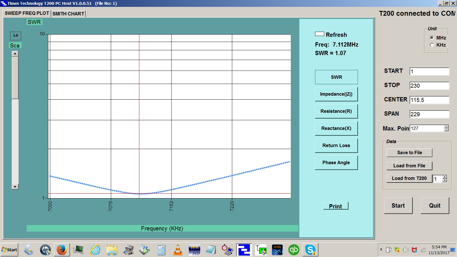
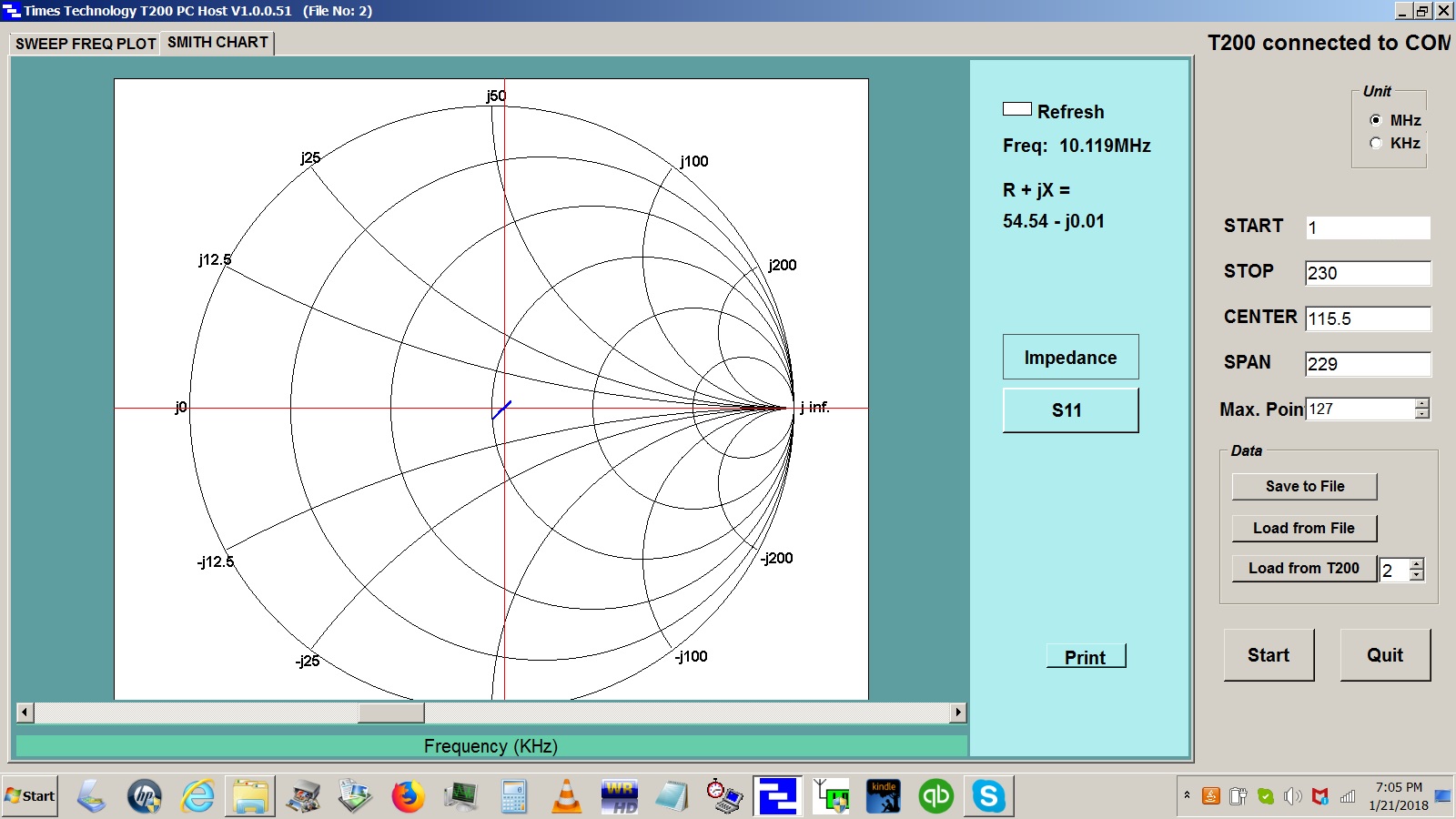
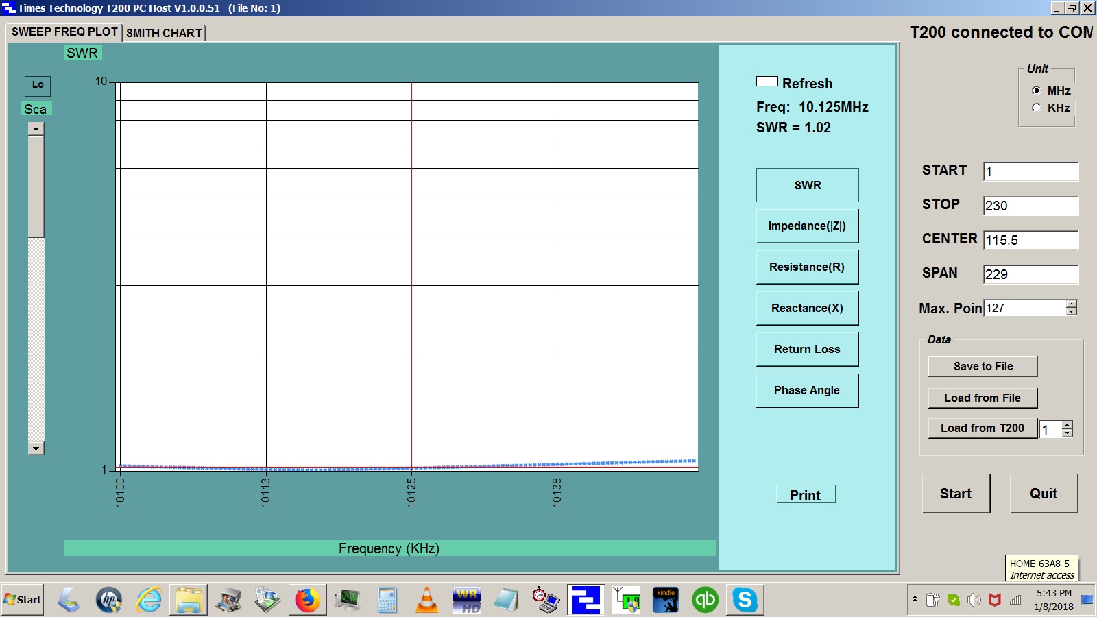
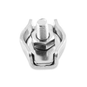
Figure 15. Wire Rope Clips. The 2mm and 3 mm variety are handy for splicing pieces of antenna wire together.

By now, you have probably figured out how to perform some reverse engineering from the field-test results. If the values of the inductance and capacitance have been determined experimentally, it is possible to work backward to determine the unloaded Q and then the impedance transformation required to obtain a match. From this, you will be able to estimate the end resistance of the wire.

Field Test Results

Some field-test results are summarized in Table 3. Many of the load impedances for the L-matching networks have been iterated, and these values appear in the table. Because of weather considerations on the test range in Florida in spring 2020, the test program was suspended. Nonetheless, all of the networks were tested and iterated, with the exception of the 80m L-matching network. This may have been fortuitous, as there was no means to elevate the 80m antenna to a height exceeding 0.25λ (66 ft) with the masts available.

All of the measurements in Table 3 were made with 50′ of RG-8X coax. The reference plane of each measurement was moved to the plane of the SO-239 connector on each L-matching network by means of an open/short/load calibration load kit.

Table 3. Spring 2020 Field-Test Data Summary. The as-built component values and VSWR results are as reported. The L-matching networks and coax were supported by a 33’ (10m) mast. The mast was judged to be of insufficient strength to support an additional common mode choke. Consequently, all measurements were made with a 50’ length of RG-8X where the entire coax acted as the counterpoise. No attempt was made to optimize the length of the counterpoise. The 80m L-matching network could not be tested because of the weather. See text.

References

[1] ARRL Antenna Book, 21st ed., Ch. 7, p. 2.
[2] https://www.eznec.com/
[3] Blustine, M., L-Matching Networks – Field Measurements, March 17, 2020.
[4] https://www.aa5tb.com/efha.html
[5] https://mfjenterprises.com/products/mfj-854
[6] https://web.ece.ucsb.edu/~long/ece145a/Notes5_Matching_networks.pdf
[7] Ibid.
[8] https://home.sandiego.edu/~ekim/e194rfs01/jwmatcher/matcher2.html
[9] https://www.66pacific.com/calculators/coil-inductance-calculator.aspx
[10] http://www.qrz.lt/ly1gp/amidon.html
[11] https://www.66pacific.com/calculators/toroid-coil-winding-calculator.aspx
[12] https://www.amazon.com/Rannb-Stainless-Simplex-Single-Diameter/dp/B07DLVNR54/ref=sr_1_7?crid=26694JFBAHN04&keywords=cable+clamp+3mm&qid=1654922072&sprefix=cable+clamp+3mm%2Caps%2C85&sr=8-7

Martin, K1FQL


Radio Amateurs Developing Skills Worldwide