We activated Mount Monadnock (W1/HA-009) on Saturday, May 25th. Myself, Brian (W1BP), Brian’s son Nick, John (KB1EEU), Mike (AB1YK) and Randall (KC1KSY) all started out from the parking lot of the park headquarters around 8:45 in the morning on a beautiful day.
KC1KSY, KB1EEU, Nick, W1BP, and AB1YK eager and ready!
We hiked the White Dot trail on the way up. This was the shortest route up, which also meant the steepest. The advantage of the steepness was that we had beautiful views most of the way up.
A quick break before it gets really steepFantastic views
Once we arrived at the top we took a quick breather and had a bite to eat before setting up our stations. Brian used a KX3 with his Buddipole mast, tripod and shock-corded whip. I used my new Buddipole shock corded mast that I got from Hamvention. John used a Xiegu 5105, which is similar to the KX2 on a crappy pole with an end-fed antenna. Mike, who is a homebrew guru came out with the Yaesu FT-817 and his home-made 6m yagi that he repurposed from his old 6m home-brew he brought to Mount Pack Monadnock.
Mike, AB1YK with the home-brew 6m yagiLove the Buddipole! No tuner needed for AC1DC
None of us created any pile-ups while on the peak, but we all had a great time. I did make one dx call to Italy which gave me enough QSOs for a successful SOTA activation.
On the hike down we traveled the White Cross trail which was less steep and still offered some beautiful views. We were all tired by the end, but looking forward to our next SOTA event!
AB1YK and W1BP descending after a wonderful afternoon
The club will be going up Mount Kearsarge for a SOTA/POTA activation during the ARRL’s VHF/UHF contest on Saturday, June 8th. Members can hike up the mountain or drive up and there should be plenty of activity on 6m and up!
The little RockMite was designed and sold by Dave Benson, K1SWL, for many years. When Dave retired from the task some time ago he was sure to hand it off to someone he (and we all) could trust to be a good steward for its legacy. That man was Rex, W1REX, proprietor of the amazing QRPme.com website. Under Rex’s steady hand the RockMite has thrived. This article will begin to look at the magic of the RockMite’s design.
What is a RockMite? The RockMite is a crystal controlled QRP transmitter that can operate on one frequency (okay, two frequencies, but we won’t get to that until later). It has a little PIC processor on the board that hosts a CW keyer and provides some feedback (through audio) of the state of the radio. The design is so small that it fits easily into an Altoids tin or other small enclosure. Third party outfits also sold very nice aluminum anodized cases that gave your radio a very finished look.
Close-up view of NE1RD’s 20m RockMite in a blue anodized aluminum case
The schematic for the RockMite is deceptively simple. Here it is (click the image to make it bigger):
Schematic for the RockMite transceiver (from QRPMe.com)
Let’s walk through the signal paths a step-at-a-time to see how the radio works.
The Receiver
The RockMite is a direct conversion receiver. That means that the signal you get off the air is processed directly and converted into audio. Contrast a direct conversion receiver with a superheterodyne receiver that has multiple steps where the original signal is translated into an intermediate frequency, processed further, then the audio is created. Direct conversion receivers are more simple than their “superhet” counterparts, but superhet receivers make it easier to make multi-band radios.
Before we can look at how the signal we receive is turned into audio we need to learn about something that I always thought was amazing. It is astonishing to me how often some obscure mathematical concept has a purpose in our physical world. Here’s the one we need now.
If you have a frequency and “mix” it with another frequency, you get the following from that combination:
You get the original two frequencies back out,
You get the sum of the frequencies,
and you get the difference in the frequencies
Imagine you have a 40m RockMite. You want to be able to listen to signals on that band. How do you convert something at 7,000,000 Hz to something at 600 Hz? You mix signals together!
The SA602/612 or NE602/612 double balanced mixer is a part that does nearly all the heavy lifting. Here is a block diagram of what you have inside this small 8-pin DIP part.
NE612 Mixer block diagram
The interesting bit in this picture is the circle with the cross. This is the mixer part. The other pieces are just there to support the mixer. Note that the mixer has two inputs: one from an oscillator, and the other from an input signal source. The mixer “mixes” those two signals and outputs the result on pins 4 and 5.
The general idea is this: apply power to pins 8 (Vcc) and 3 (ground). Then hang enough parts between pins 6 and 7 to have the internal oscillator create a steady signal. This can be a crystal oscillator, or just a capacitor and inductor network, depending on your needs. Then apply a signal to pins 1 and 2. The results (f1, f2, f1+f2, and f1-f2) appear at pins 4 and 5.
If we configure the oscillator to be, say, 7.040 MHz, then mix in a signal near that frequency from our antenna (say 7.041 MHz), the mixer should create our four products (7.040 MHz, 7.041 MHz, 14.081 MHz, and 0.001 MHz, which is 1 KHz. That frequency is a little high for comfortable audio listening, but it is within the audio range. If only we could snag only that frequency and ignore the others.
We can. We run the results of our mixing through a low-pass filter and we’re left with only frequencies below that filter’s limits. Then again, if we are only doing audio processing those other frequencies become nearly invisible. (Good headphones might respond to 20 Hz to 20 KHz, but a frequency of 7 MHz is going to do nothing!) Let’s look at the mixer part of the receiver in the RockMite.
RockMite Mixer
The direct conversion receiver mixer
The signals come in on the left and go left-to-right. The point (A) on the diagram is a connection to the antenna. That is the source of our CW signal. It travels through a capacitor C1 to AC-couple the signal to the remainder of the mixer. We then have a couple of back-to-back diodes D1 and D2 that are used to clamp the amplitude of the signal received. This protects the rest of the circuit should we get an unusually strong signal from a nearby transmitter or a lightning strike somewhere. Diodes like these “turn on” (conduct) in the forward direction when there is 0.7 Volts present. We hope our radio signals are strong, but not that strong! So, if there is an exceptionally high voltage (RF-wise) then we want the diode to turn on and shunt that signal to ground. In normal operation, those diodes sit there and never turn on.
The signal is then pass through a crystal for this band. The RockMite we are studying is built for a single frequency: 7.040 MHz. By sending the signal through a crystal of this frequency we allow signals of that particular frequency to pass easily while rejecting other signals far from 7.040 MHz. By the time our signal is on the right side of that crystal, it should be a reasonably pure signal near that frequency.[I’m going to ignore the capacitor C2.]
What we have left is the mixer! I said that power comes in through pins 8 (+) and 3 (-). For pin 8 we have a connection to V+ (our power supply) running through a current limiting resistor R1. We also have a connection to ground through a Zener diode. Zener diodes are interesting because they can be used as a very simple voltage regulator. In this case, the diode D3 is a 6.0 Volt Zener. That means that the diode “turns on” when it sees a voltage above 6.0 Volts and maintains a 6.0 Volt potential at its feed. So, if V+ is 6.0 Volts then the diode probably does not even turn on at all. If V+ is 6.1 Volts then the diode turns on just enough to bring the voltage back to 6.0 Volts.
The SA612 Mixer is powered at 6.0 Volts because of the Zener diode. The resistor R1, therefore, is the current limiting resistor to protect the Zener D3. The C101 capacitor is connected to ground just to filter away any spurious noise that is on the power lead going into the mixer.
Pin 3 of the SA612 is connected directly to ground. With these two pins configured, we have successfully powered the device.
Pins 1 and 2 of the SA612 are the input to the device. This is where we send in the signal we want to process. Pin 2 is connected to the signal path and the crystal Y1. Pin 1 is connected to ground (though through an AC coupling). That’s our input for the signal. Now we need to mix it with something.
The Oscillator in the SA612 can be driven with passive parts (like crystals, capacitors, etc.), or it can be driven directly from an external oscillator through pin 6. That’s the decision Dave Benson made when he designed this radio. So, for now, assume that the signal coming in from the outside directed at pin 6 is from an oscillator not pictured. Again, like so many other things here, this is AC coupled through a capacitor (C3 in this case). We now have our baseline frequency.
If the input frequency from point (A) in the diagram is 7.041 MHz, and the oscillator coming in through pin 6 on the SA612 mixer is 7.040 MHz, then we will get the four products we discussed (the original frequencies from our two sources, and the sum and differences of them). That is precisely what is produced in our pins 4 and 5 on the SA612 mixer.
The hard part of the radio is done! We have taken a signal off the air and converted it into something our ears can hear. All we need to do is make it loud enough. To do that we use a single-chip amplifier solution built around the LM1458 Operational Amplifier. (Note that Benson only needed to use one of the two OpAmps on the device. Even with the design this compact he had excess capacity!) Here’s the part of the schematic for the audio amplifier.
The audio amplifier stage for the RockMite, enough power to drive headphones
Here is the block diagram for the LM1458 device.
The LM1458 Dual Operational Amplifier
I’m not going to go through how the audio amplifier works. (I’m not all that hot on good amplifier design!) But, you don’t need to know much here except (1) the output from the mixer drives the amplifier directly. The output of the amplifier is run through a transistor switch Q1, a 2N7000, that can connect, or disconnect, this amplifier from the headphone jack. Why do we need this?
The RockMite is a transceiver. When we are transmitting it is nice to be able to hear a “sidetone” of our keying. When we transmit the switch (Q1) turns off the signal path to the audio amplifier and the “Sidetone” signal (that comes in from another part of the circuit) drives the headphones instead.
What’s next?
This concludes the discussion of the RockMite’s receiver. I’ll continue on with follow-up articles for the radio’s oscillator, the keyer, the transmitter, and final amplifier, and the output filtering starting next month.
At least some of my interest in ham radio can be boiled down to my curiosity. How did they do it? How does it work? Why does it work? My college degree is in Computer Science, not Electrical Engineering, so I needed to start small and work my way up.
Radios do not need to be complicated to work. Like many of you, I imagine, I built a crystal radio and listened to AM broadcasts as a child. It seemed mysterious at the time (and still does, to a degree) that this simple collection of parts: a coil of wire that I sanded and tapped to tune, a small “diode” (whatever that was), and some earphones could take radio waves from the air and create sounds.
One of the reasons I became a ham was to learn a little more about how radios work. I think that’s why I gravitated to QRP stuff so early in my adventure. The radios were small and simple (at least compared to the big Icom I had on my desk), and yet they were “complete” transceivers. As a kid I would take apart anything I could find to see how it worked. (My survival probably depended on my being able to put things back together; I was relentless!) These small radios seemed like a gateway to learning.
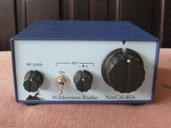
Back in the early 1990s, Wayne Burdick, N6KR, designed a small, trail-friendly transceiver for 40m that was to become the NorCal (Northern California QRP club) 40. He completed this design by himself in three days! There wasn’t much to this radio. It had a couple of knobs, a BNC antenna connection, and two jacks for headphones and key. Later versions of the device produced by Wilderness Radio (called the NorCal 40A) included a keyer with memories, a boon to anybody working portably.
Wilderness Radio’s NorCal 40A photo from K7NIB (used without permission)
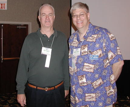
A destination of note for all things QRP and radio is the Chuck Adams, K7QO, website. In particular, I’ll point you to the catalog of YouTube videos Chuck has discussing many aspects of radio design. There are a couple of different builds for the NorCal 40A: one done Manhattan-style and another done on a PCB. You don’t need the kit to build the radio! Chuck shows you how to do-it-yourself.
http://www.k7qo.com/k7qo_youtubes.html
Me with Chuck Adams, K7QO, in 2006 at the Four Days in May convention in Fairborn, Ohio.
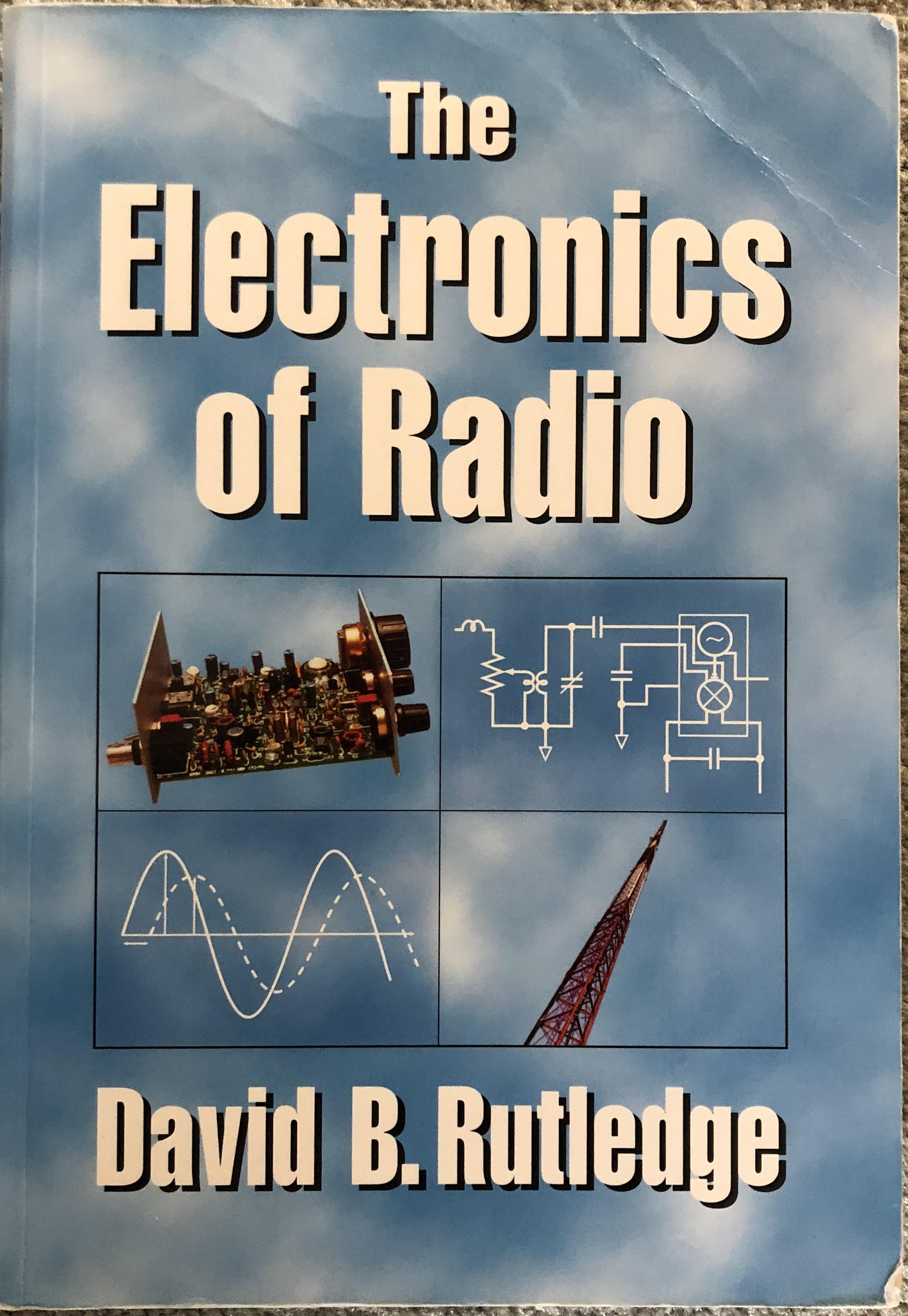
Alas, like so many things in our kit world, this radio is no longer in production. That is a shame for there is a whole book dedicated to teaching Electrical Engineering principles call “The Electronics of Radio” by David B. Rutledge, KN6EK, that uses the NorCal 40 throughout. The book is still available on Amazon.
The book walks students through filters, transformers, transistor switches and amplifiers, oscillators, and mixers, all using the NorCal 40 as the example. As students build up the radio they learn how each piece works, and how it all works together. I recommend this book even if you never intend to build this radio.
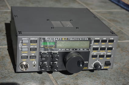
Where this story picks up, though, is when Wayne Burdick and Erick Swartz, WA6HHQ) start the company Elecraft. Wayne’s NorCal 40 proved there was a market for radio kits, and radios with hot receivers and very-low power consumption. Their first offering was the K2, a multi-band radio. It was not unusual for DXpeditions to carry these Elecraft K2s to faraway places because of their exceptional performance. You can still buy K2 kits ($799.95).
Elecraft K2 transceiver. Photo credit B. Scott Andersen, NE1RD.
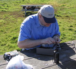
While the K2 is a wonderful radio, it isn’t exactly trail friendly. Here I am in San Francisco’s Golden Gate Park with my trusty K2. I was going to do some winter sprint contest of some kind, but the final transistor was shorted to the case and the radio wouldn’t work. I walked to a nearby Radio Shack® and bought enough tools to at least open up the radio and diagnose the problem. (I miss Radio Shack!)
Me at a picnic table in San Francisco’s Golden Gate Park in 2005.
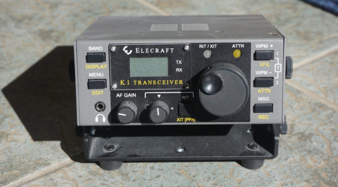
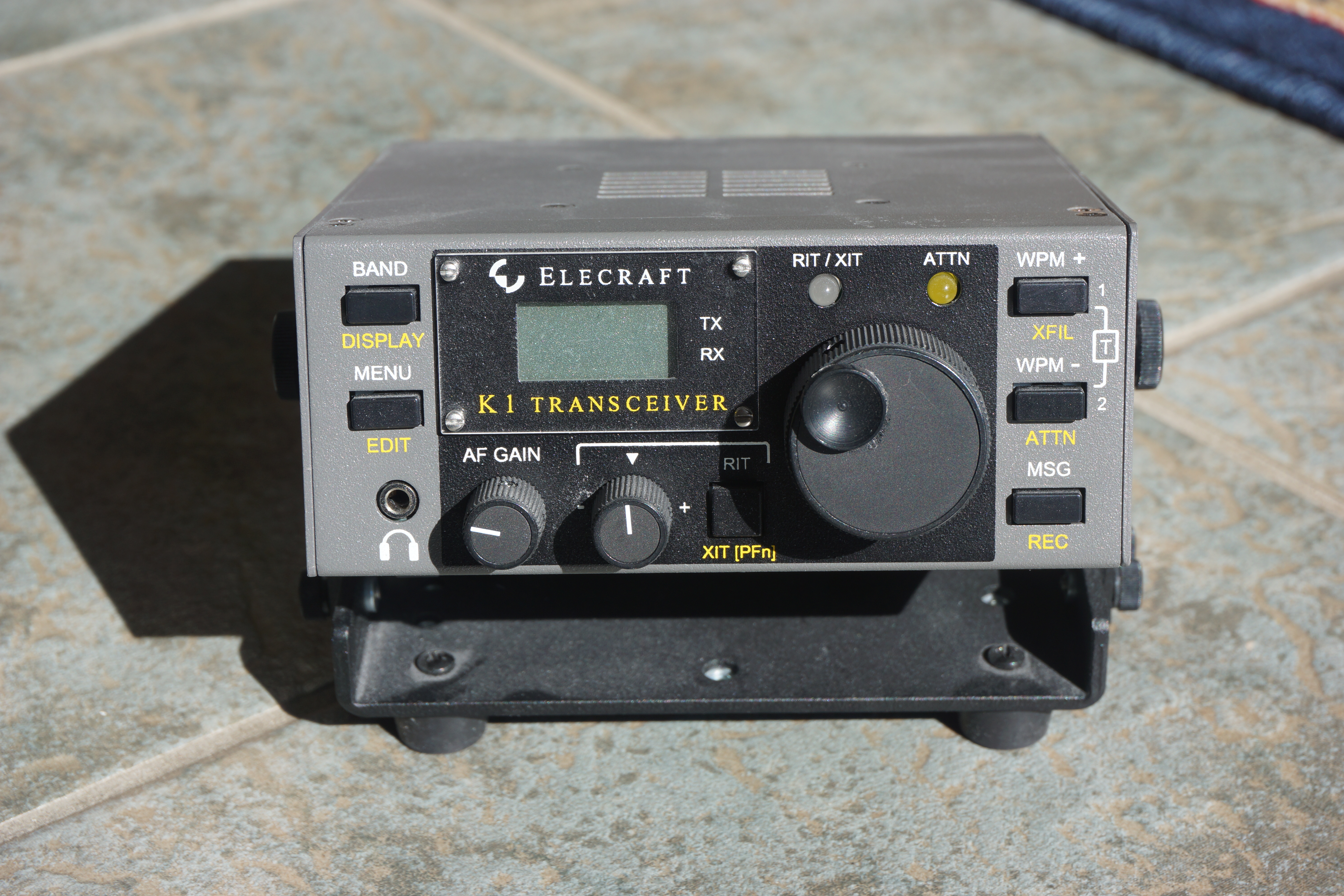
A simplified version of this radio, the K1, came soon after the K2. The K1, unfortunately, is no longer in production. Some combination of lower demand and problems finding the through-hole parts needed by the kit doomed it. Nevertheless, the manuals for the radio are still available on the Elecraft website. You can download the complete K1 manual here: K1 MANUAL.
Elecraft K1. Photo credit B. Scott Andersen, NE1RD.
There are complete schematics for the radio and this wonderful block diagram illustrating how the radio components fit together.
K1 block diagram from the Elecraft manual. Used without permission.
I highly recommend fetching this gem if only to have the block diagram and the radio’s schematic handy. I printed out the schematic (just four pages, and really only two that are interesting) and carried them with me everywhere for a couple of years. I would occasionally take out these pages and follow along the signal path to see how Wayne Burdick and Eric Swartz did it.
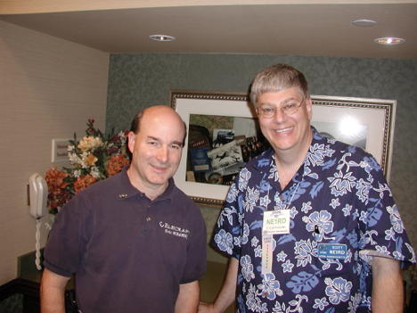
Me with Wayne Burdick (N6KR) in Dayton 2006.
The K1 manuals are free. Chuck Adams’ YouTube videos are free. There is a lot you can do to learn about how radios work by “taking apart” some of the best designs QRP radios have ever had. The K1 is such a radio.
Please take a moment and get that Elecraft manual for the K1 and give it a look. Skip past all the assembly steps and go straight to the back with the schematics and block diagrams.
I’ll go into the RockMite in my next article and walk through how the radio works.
We use cookies to ensure that we give you the best experience on our website. If you continue to use this site we will assume that you are happy with it.