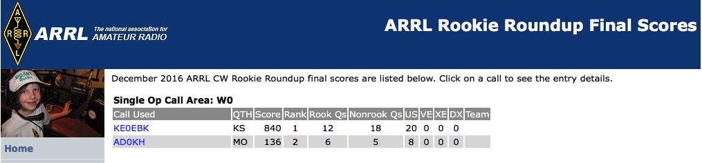
The scores are in! The N1FD team placed #1 in Area 1 Multi-Op category in the ARRL Rookie Roundup CW! We have won the Area 1 Multi-Op category in all three Rookie Roundup contests this year. The complete results can be found here.
2016 ARRL Rookie Roundup CW Final Scores
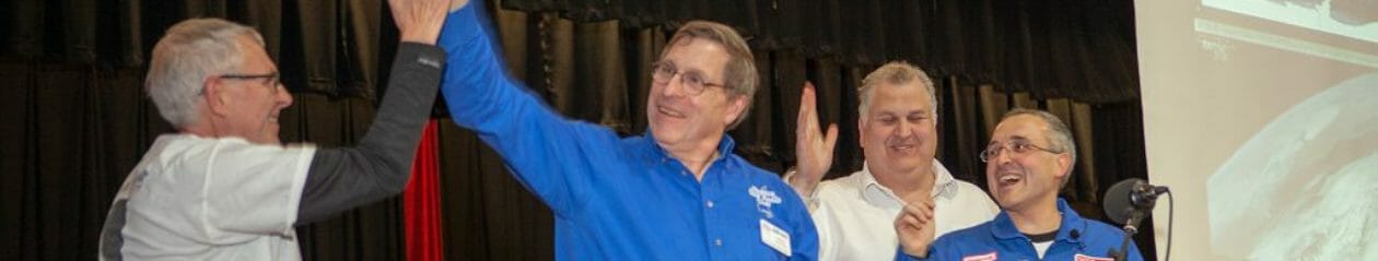
Congratulations to Abby, KC1FFX and Jamey KC1ENX, who operated in the contest!
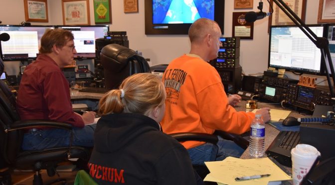
The N1FD Contest Team operated in the final Rookie Roundup of the year – the ARRL Rookie Roundup CW. Jamey, KC1ENX and Abby KC1FFX operated as a Multi-Op team using the N1FD callsign at the QTH of AB1OC and AB1QB.
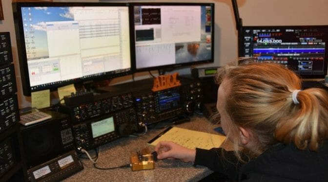
Abby, KC1FFX in the Rookie Roundup CW
The CW contest proved to be a great way to improve the CW skills of the rookies as well as the Elmers! It was the perfect follow-on to the Morse Code Class held earlier this year.
N1FD Multi-Op Score in the ARRL RR CW
Abby and Jamey made a total of 21 QSOs in the contest, including one with another rookie from Alberta, Canada. Most of the activity was on the 20m band with a few contacts on 40m.
US States and Canadian Provinces Worked in the Contest
We all had a great time in the contest and are looking forward to working another CW contest soon.
We’re also looking forward to the next Rookie Roundup, the SSB contest which will be on April 17. We invite all of the new hams in the club to join us for the SSB version of the contest.
Let me begin by setting the scene. Imagine bone-chilling cold…It was colder. I was going to wait outside for Fred (AB1OC) and Jamey (KC1ENX) but the biology supporting my internal survival mechanism had other plans.
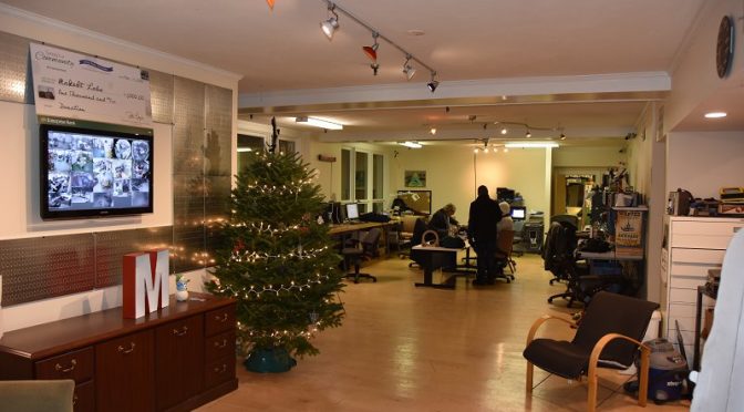
Bravely, I opened the door and was quickly greeted by John Bottoms. Interesting name, but a cool guy. We chatted for a bit and it turns out he’s working on embedding AI into VR…I think I have that right. He quickly pointed out that Thursdays are MakeIt Labs (see their web site) busy days since that is when they host their open house. I did see all around me many people working viciously on their projects. Truly, it was maker heaven.
Not long after, Fred and Jamey showed up and we were ready to begin our tour. Well, almost ready. There was a brief, but awkward exchange among two of the volunteers about who would be giving the tour. I was starting to wonder why it was so long and drawn-out. Odor-eaters in my shoes? (Check), Deodorant applied? (Check)…so it couldn’t be me. Eventually, the two fellas realized a better alternative to suit both their agendas was to elicit the help of a 3rd fellow. That fellow was Doug; he’s good people.
Machine Lathe
Doug began by taking us into the garage. Man, you all have to see this place. Woodworking shops, machine shops (including lathes and CNC machines), a litany of other heavy power tools to make the biggest kid drool), a plasma cutting machine, a mechanic’s shop to bring your vehicle to tune it up — change the oil — or add nitrous. This. Place. Was. Awesome.
CNC Plasma Cutting Table
Fred was definitely familiar with the tools and instruments there. Jamey and I looked awed but bewildered. During our combined awe-strike, Fred found himself in a conversation with another knowledgeable gentleman named Andrew about plasma cutting through steel. It began harmless enough. They were telling each other about the thickest piece of steel they ever cut through. But soon, you could tell the other could not be outdone. By the end of it, I swore I heard tall-tales of karate chopping through 4 ft. titanium able to withstand a nuclear strike. All pretty cool stuff. (I may have embellished a little)
CNC Vertical Milling Machine
We continued the tour to the electronics portion of the lab where they had 3D printers (and another one in color), a spare electronics parts room, networking stations, dudes flying around mini-drones. We also saw they had a fabric station where folks could come in to sew. I was surprised there wasn’t a line for this. Making blankets seems like the right thing to do currently.
CNC Laser Cutter
We saw multiple conference rooms available, a room for the FIRST robotics team they adopted, office space for folks with start-up companies — something for everyone.
Laser Cut Wood and Polystyrene Projects
By the conclusion of the tour, we got to meet a member of their Board, Bill. (Hi Bill!) This guy was definitely on board with bringing amateur radio to the masses. He liked our ideas of setting up for Kid’s Day (or some variant of it), of our near-space balloon project, teaching license classes and/or intro. to amateur radio courses, and even helping us advertise before we arrive. I think he saw the strong parallels between what they do and what we do. This could truly begin to be a very useful symbiotic relationship.
So with our visit over, I would recommend to those of you who have not had the pleasure, get yourself out to MakeIt Labs. If you have questions, please contact me, Jamey, or Fred. (Fred became a member tonight, so he knows the secret handshake). I think if you have ideas, projects that you’ve always meant to get done but haven’t found the time yet — this is the place for you. I think after you see this place, and if you were on the fence about getting involved in the Club’s Youth Outreach effort, I think you’re going to be all in after visiting.
We use cookies to ensure that we give you the best experience on our website. If you continue to use this site we will assume that you are happy with it.