Tag Archives: Kits

QRPGuys Iambic Paddle Build

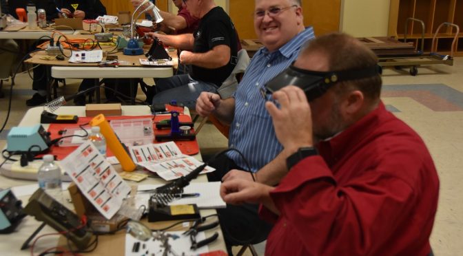
I’ve been practicing a lot of CW lately and had ordered a QRP guys iambic paddle from their website qrpguys.com awhile back. I went to the CW class on Saturday morning, which got me in the CW mood. After knocking some items off the honey-do list I was getting a little bored on Saturday night so I headed down to the shack and dug out the iambic key kit I had ordered.

I’ve never done any kit building or anything slightly engineer-y until joining the club. I don’t always understand why things work and building kits (even simple ones help me along). This kit didn’t look too hard, although it has a 4 out of 5-star difficulty rating on their website, so I jumped right in!

I made sure I started by sorting out all the parts in an orderly fashion.Iambic Paddle Build  I learned this much from working countless hours after Christmas and birthdays on Star Wars lego kits that are made for children, but built by adults after the kids get frustrated 15 minutes after starting!

I then got to the fun part of soldering. This was different than what I’ve done in the past as I started with soldering all the mechanical parts together by applying a small amount of solder and then checking to make sure everything lined up before putting a lot of solder on. Iambic Paddle BuildI enjoyed this as it was a large area to solder and it didn’t matter so much if my soldering skills aren’t very good! There were only a few electrical components to solder and that part was rather easy, even for my limited skills!

The toughest part of the whole build was assembling the paddles. You can see from the picture there are four nuts (and lock washers) that are to be assembled on the inside of the paddles with very limited space. TIambic Paddle Buildweezers were an absolute necessity – and earplugs for any youth that may be hanging around. After many – and I do mean many – attempts of dropping and picking up nuts and washers I finally got the washers and nuts in place and fastened.

Iambic Paddle Build

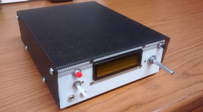
I was thrilled to have succeeded and ran out to the car, where my radio is hooked up at the moment and gave it a quick test run. Below is my not-so-professional video which shows my not-so-professional CW skills.

The paddles work well. The black pads do stick together a little when you push on both paddles at the same time, but I am very happy with my tiny QRP paddles! I am thinking of cutting slots in the sides and attaching a velcro band to attach to my leg to keep the paddle in place in the hopes that I could operate it with one hand. Let me know what you think or if you’ve built this kit before.

73,

Jamey (KC1ENX)

My SSB BitX-40 build from VU2ESE

Below is a photo of my BitX-40 kit from Ashhar Farhan VU2ESE in India with my very own custom designed case.  The kits are available from http://www.hfsigs.com/

The top cover shown is powder coated steel mesh.

BitX-40 Enclosure

The sheet metal housing was designed in a solid modeling software package called Onshape. This web based software is free to use if your designs are to be available to anyone who signs into an account.  This design is “in the cloud” and considered “open hardware”, available to anyone who would like to use it.  Below is a screen capture of my Linux desktop running Onshape within a web browser.

BitX-40 Enclosure CAD Design

With access to a CNC punch press and a 90-ton brake press, a coworker of mine helped out with a bit of “government work”!

I left out some of the detail in the housing to let others enjoy the use of a drill and allow for some creativity with a customized placement of components.

BitX-40 Enclosure with Board

Some of the wires are not needed but may be useful in future “hacks”. The image below shows some of the wires removed from the “Molex” connector.  A small sharp object can be used to push in on the barb to remove the contact for a future project.

BitX-40 Cables and Connectors

See http://bitxhacks.blogspot.com/

I used my sketch to drive the LCD screen and the SI5351 chip using the Adafruit library.  The checkered block moves left and right between the arrows to indicate when I am at or near the end of travel with the tuning potentiometer.

BitX-40 Frequency Stationary
Stationary

When I move the block all the way to the right with the potentiometer it turns into an arrow and automatically increases the frequency. To make it stop just turn the potentiometer to the left.

BitX-40 Frequency rising
Frequency rising

I like the ability to scan the band without having to turn a knob!

Below is an image showing 12v and 24v voltage regulators and electrical tape on the housing tabs.  12v is for the majority of the wiring and I used 24v for the IRF510 PA.  The black tape looks nice behind the black mesh cover.  while testing I measured about 4W RF output with 12v feeding the PA and 16W RF at 24v.

BitX-40 Enclosure

The bottom has extruded “feet” along with stick on feet to keep the rig from sliding.

BitX-40 Enclosure

I used an SO-239 connector for the antenna.  I saved the BNC connector from the kit for test gear.  The red terminal post is connected to 32v from a repurposed HP printer power supply.  The barrel jack is connected to 16v from the same supply.

For more information on the case, you may contact me through my QRZ page.

73,

Mike (AB1YK)

Our Latest “Tech Night” – A DSO138 Oscilloscope Kit Build

Our latest Tech Night became a Tech Day this past weekend. We got together on Saturday afternoon to build another kit – the DSO138 Oscilloscope. We had a great turnout with over 15 kit builders and helpers present.

Finished Oscilloscope Kit
Finished DSO138 Scope Kit in case

Brian, AB1ZO choose this really cool kit for us to build. Here are some specifications for the finished DSO138 Oscilloscope kit:

  • Analog bandwidth: 0 – 200KHz
  • Sampling rate: 1Msps max
  • Sensitivity: 10mV/Div – 5V/Div
  • Sensitivity error: < 5%
  • Vertical resolution: 12-bit
  • Timebase: 10us/Div – 50s/Div
  • Record length: 1024 points
  • Built-in 1KHz/3.3V test signal
  • Waveform frozen (HOLD) function available

The kit came with all Surface Mount parts pre-installed.

The kit included a very nice case to finish off the project. This was a pretty big project to complete in a single afternoon but quite a few of our builders completed their kits and got them working!

The gallery below contains more pictures from our kit build. Everyone was very focused on the building process as we all wanted to get our kits to work in the time we had together.

Some folks did not quite get their kits completed and are planning to finish them at home. The following are some links and videos to help.

Here are some videos which show the assembly of the kit and its enclosure and the operation of the completed scope. The first video shows the kit in operation.


I know that Brian is planning to do more kit builds throughout the year so be sure to keep an eye on our Tech Night page to see what is coming!

Fred, AB1OC

Radio Amateurs Developing Skills Worldwide