If you have an old wire antenna or even a newer wire that you haven’t been using all that much, consider re-purposing it for a new challenge: Medium Frequency (MF). Many radio amateurs don’t realize that 630m (475 kHz) is very accessible. For instance, a transverter, QRP transceiver, and a simple load coil and transformer match assembly are all that is usually needed to utilize a new or re-purposed wire antenna.
If you have something close to an inverted-L wire antenna, say with a 35 feet vertical section and a 50-100 foot horizontal section, you are very close to having a reasonably efficient short top-hatted Marconi antenna for MF. It will never be resonant but will be a good Rx/Tx performer. Additionally, they will work very well for North American NDB, Non-Directional Beacon, reception. These antennas will work perfectly with any of the commercially available transverters such as the Monitor Sensors, TAPR QRP transmitters, or the popular K5DNL PA for 630m. Using any of the on-line calculators to figure out exactly what inductance load you need based on your specific wire configuration has never been easier. For example, VK1SV maintains an excellent short Marconi calculator here. It gives you all the parameters for a wide range of frequencies and wire types.
The Project
This project was to re-purpose an existing older wire inverted-L that I wasn’t using. The wire was composed of a 35’ vertical section and a 100’ horizontal section. First of all, using the online calculator gave me a rough estimate of around 100 uH needed to utilize my existing wire. Then, using an inductance coil calculator, I arrived at the least expensive method to build the inductor, using two 8” PVC couplings (glued together) and about 100’ of 14 AWG stranded wire. A liberal span of internal taps was included for adjustability and tuning. I also added an SO-239 connector. As a result, the coax attachment will be much easier. Also, placing a small corona ball on the antenna side will provide additional protection from the kiloVolts of antenna voltage.
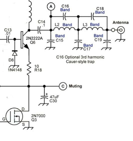
The matching transformer was tie-wrapped to the inside of the inductor. It was built simply by taping two Fair-Rite type 43, 61mm OD, cores together and using 28 turns tapping every two turns. Care must be taken to attach the toroid assembly outside of the inductance coil zone. One side of the transformer is connected to ground and the other contained an alligator clip for easily attaching to the load coil tap. The schematic diagram and mechanical configuration are shown in Figures 1 and 2.
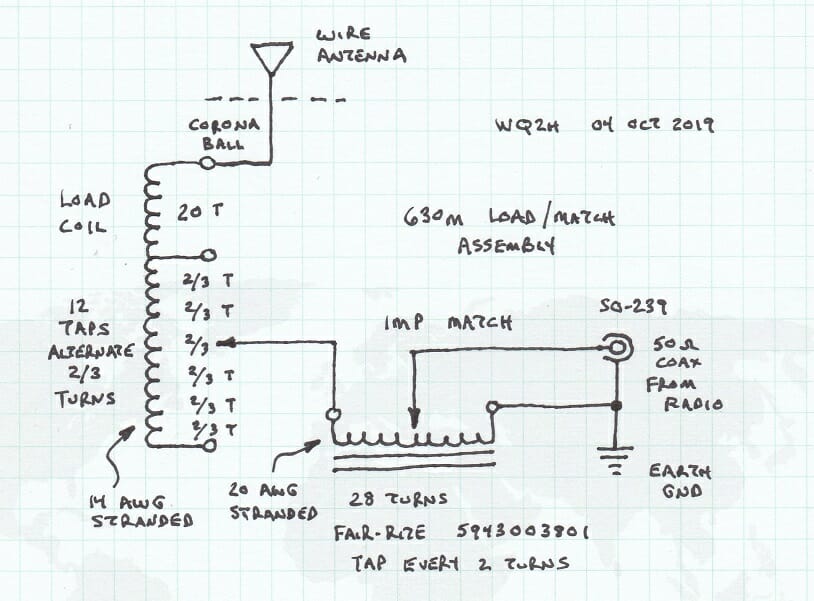
Figure 1 (adapting Dennison, 2013 p 37) (1)

Figure 2 (1)
A Low-Cost Enclosure
The entire assembly is small enough (~ 8” dia. X 12” high) to fit in a two and a half (2.5) gallon pail. You can manage the cables through a separate snap-on lid. The pail yields a waterproof assembly that can be left outside of the shack and at the base of the vertical wire section. This keeps the “hot side” of the coil and higher voltages away from your shack and house. Most importantly, a separate earth ground connection is required. Using a single vertical ground rod, position it close to the SO-239 connector. As a result, most stations will see improved performance. See Figure 3. While radials would also certainly improve performance I have yet to experiment with adding them. A PolyPhaser or spark gap can also be added for static/lightning protection.
Make sure to isolate the antenna (hot) side on the coil and antenna wire. Additionally, using insulators at the antenna wire extremities and bend point is always necessary. As a result, this will provide isolation from the several kiloVolts of voltage that will be present on the wire during 630m transmit.
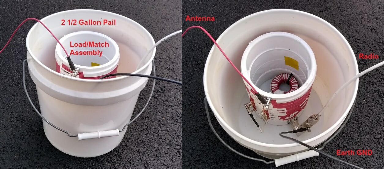
Figure 3 (1)
Testing and Performance

CAUTION – High Voltage (~2kV) will be present at the antenna feed point during testing. Moving the alligator clips to achieve the best match is an iterative process and may take several attempts. Do not attempt to work on or adjust the Load/Match unless the coax feed line is disconnected and the radio is turned off.
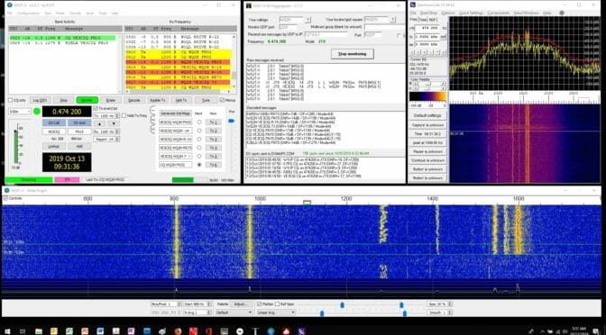
The first radio test went very well. (beginner’s luck I suppose) The lowest SWR I could achieve was 1.4:1. However, a higher resolution on the tap spacing would probably have yielded a better ratio. But this was plenty good enough for a first test for the time being. I used a Monitor Sensors TVTR1 transverter with a conventional HF transceiver. As a result, I was able to make about a dozen 630m JT9-1 QSO’s in the first week using the repurposed wire and homebrew load match assembly. Likewise using the WSJT DX Aggregator, I was also able to report activity by over 60 stations across the country. See Figures 4 and 5.
From the calculator, given 50W into the load coil would yield about 500mW EIRP. While this is clearly inefficient by any measure, it is plenty of power at 630m to reach across the continental U.S., and potentially beyond.

Figure 4 – 630m JT9-1 QSO (1)
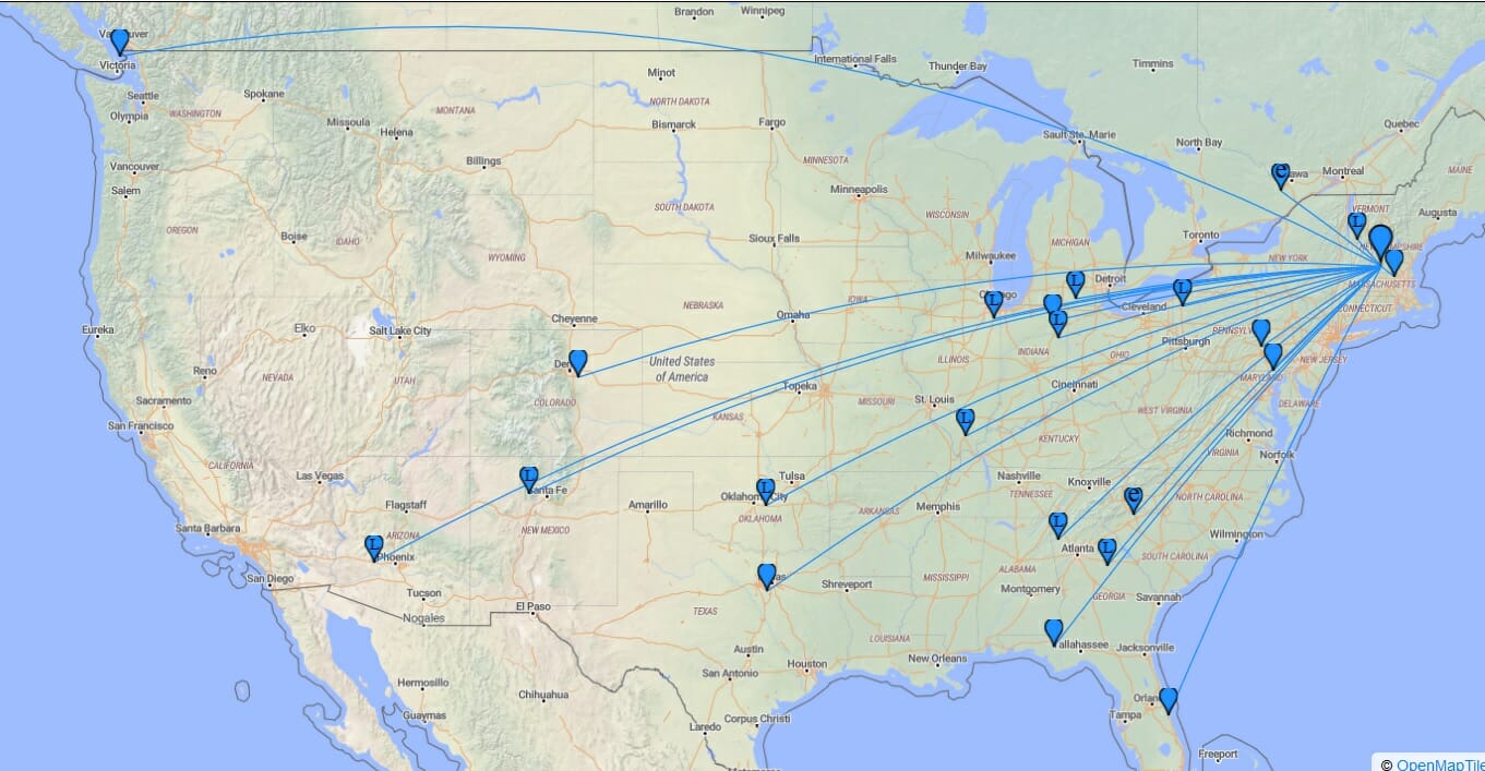
Figure 5 – First 630m JT9-1 Rx reports from FN32xv (2)
Results
As of 24 Oct 2019 the Rx record is W7IUV 3715 km @ -27 dB S/N, and JT9-1 QSO record is KB8U 1027 km @-25 dB S/N. Given the low cost, the amount of time to build, and the immediate on-air results, this approach for an MF load coil/match assembly is a worthwhile project for anyone wishing to explore MF.
Finally, the bulk of the cost for MF capability will still be the transceiver. However, if you’re a project builder with good patience and soldering skills, the TAPR Ultimate 3S kit for $33 is a good introduction. Also, the TAPR transceivers make available an LPF for 2200m – but that’s an entirely different can of worms. (The short Marconi calculator will show you that!) If any readers have an interest and/or any other questions about this project feel free to contact me directly: [email protected].
73 – Jim, WQ2H / WK2XAH
References
Dennison, M (2013). LF Today – A Guide to Success on the Bands Below 1MHz. Radio Society of Great Britain, London
Giles-Clark, J (2014), 630m (472-479kHz) Amateur Experimentation VK/ZL, Presentation. Retrieved October 24, 2019 from: http://www.spirat.com.au/vk5fq/media/630m_in_VK-ZL.pdf
Kelly, P (2019). Adding 630 and 2200 Meters to the MFJ-259B. N1BUG Adventures in Radio. Retrieved October 24, 2019 from: http://blog.n1bug.com/2016/12/22/adding-630-and-2200-meters-to-the-mfj-259b/
Severns, R (2017). Capacitive Top Loading. Antennas By N6LF. Retrieved October 24, 2019 from: https://rudys.typepad.com/files/chapter-3–1.pdf
Spirat, S (2018). 630m loaded Inverted L Antenna. VK5FQ Antennas. Retrieved October 24, 2019 from: http://www.spirat.com.au/vk5fq/630mAnt.htmlhttp://www.spirat.com.au/vk5fq/630mAnt.html
Carey, K (2007). Listening to Longwave – The World Below 500 KiloHertz. Universal Radio Research. Worthington, OH
Ouwehand, M (2017) 472 kHz Projects – Antennas. Retrieved October 24, 2019 from: http://www.pg1n.nl/articles.php?lng=en&pg=1270
(1) Image courtesy of WQ2H – Jim Poulette
(2) Image courtesy of PSK reporter and OpenMapTiles.org